7,200-segment, 1,152-digit 7-seg display
48 display controllers over three I2C buses; 288 four-digit 18:88 clock displays (25 segments per display); full 8-bit PWM grayscale control
48 display controllers over three I2C buses; 288 four-digit 18:88 clock displays (25 segments per display); full 8-bit PWM grayscale control
To make the experience fit your profile, pick a username and tell us what interests you.
We found and based on your interests.
I think the biggest technical challenge with this project has been powering it!
In general, the project draws around 10A at 5V; I have set myself an overall maximum power budget of 20A.
The older displays I'm using are not the most efficient--it takes a fair amount of current to get a decent level of brightness out of them. Since they're scanned across a matrix, meaning each LED die only gets brief pulses of current with plenty of time to cool down in between, you can get away with more than the "maximum" 20mA continuous current for an LED; even 100mA can work fine for scanning a multiplexed display like these. I bet some of you have done even more.
So on the one hand, my goal is to pump as much current into the LEDs as possible, to ensure that the display has a reasonable brightness with a wide variety of lighting, such as indirect sunlight inside a home or gallery.
But then there's just the sheer quantity of displays here. If I start drawing 100mA across 6 displays, even though each LED die only sees it for 1/12 of the time, I'm still continuously drawing perhaps 80mA per display continuously (allowing for some "blanking" time in between as the controller's transistors switch)... That'd be, uh, 480mA per panel or 23A continuous current draw. It's certainly possible to get power supplies that can do this--but the wiring and power distribution also become a headache. Using a wire with too small a gauge could cause it to heat up to the point of melting its insulation, at which point, problem!
To my understanding, wires heat up with the amount of current passing through them, not the wattage. So in general it can make sense for a project like this to use as high a voltage as possible, so that a given wattage draws lower currents, keeping your wires cooler.
The IS31FL3733 display controllers I'm using accept a reasonable range of voltages: 2.7-5.5V.
If I wanted to keep things convenient for interfacing to the Pi's 3v3 I2C bus, I could just use that voltage to power the whole system. But I felt it was worth the current-reduction payoff to run 5V to each controller, meaning that I need PCA9306 level converters to bring the Pi's 3v3 signals up, as mentioned in another build log.
The IS31FL3733 does have separate pins for supplying the switching power and VCC, but they seem to be connected internally in a weak way, such that you can't, say, power them at different voltages or disconnect VCC to power-cycle the controller. (Found that out the fun way.)
I built this project around a Mean Well 5V/40A power supply in a separate enclosure, connected via a very short run of AWG12 wire. This 5V hits the Pi's "warm bath" board through PTCs and MOVs, and also three different distribution boards that are designed to protect against short circuits or other high-current failures. Due to last-minute mistakes, I needed to hand-build these distribution boards, which you can see in this progress shot:
(thank goodness for those freebie Perma-Protos!)
This was an in-progress shot, showing the rough arrangement before I cabled everything up properly. I am using a number of 3d-printed cable restraints to keep individual wires tucked away inside the channel of the 2020 extrusions.
Each display panel has a reasonable amount of capacitance, and in general I haven't seen instabilities or flickering. I chose to configure the display controllers with high current draws via their sense resistors, and to use their software-configurable brightness controls to reduce the overall system brightness to 31/255 maximum brightness. It could get a lot brighter, given stronger power distribution and larger cables. With appropriate software safeguards, I am more comfortable having "headroom" in the application's brightness control for future reconfiguration as needed.
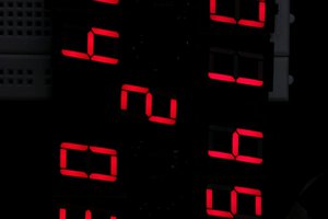
Here's an early test of power draw, doubling as a chance to see which segments were missing:
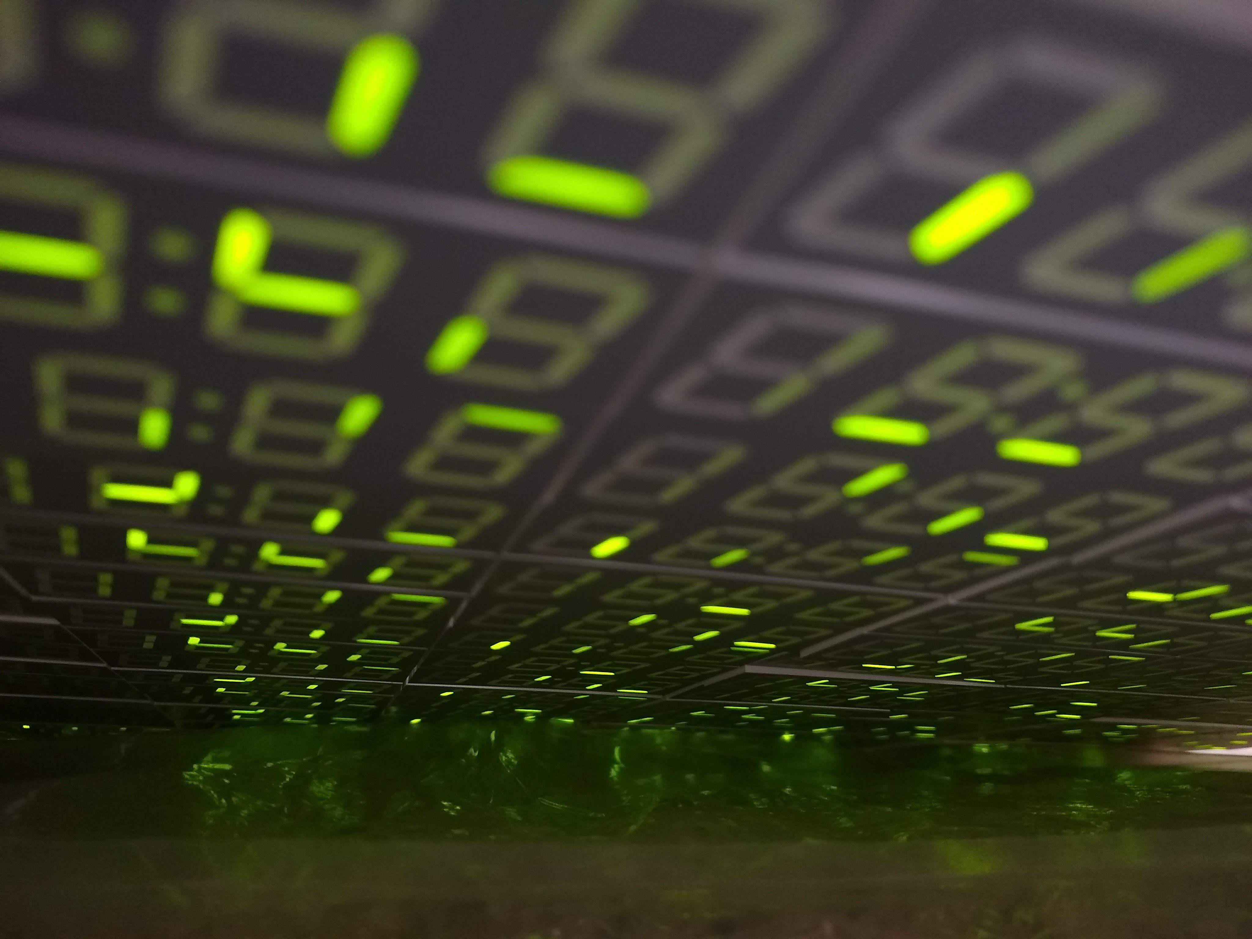
(First light)
I really like the IS31FL3733 i2c matrix controllers I'm using in this project, but they do have one limit that I ran into fairly quickly. You can only have 16 of them on one i2c bus. Due to the large numbers of displays in this project, I needed to use 48 of them.
It's possible to use a multiplexer to fit more devices on to a single bus. But there are other problems with so many devices on a single bus: bus capacitance begins to be a problem (can each device quickly overcome the increasing capacitance to drive the bus to ground in a timely manner? this takes more and more current), as does having enough bandwidth to update all of the displays at a reasonable framerate.
I began to wonder about using multiple i2c buses. The Raspberry Pi 4 has device tree overlays that enable something like 6 buses total. I had used one extra bus in a recent project ("Madness Method"), but only in a low-bandwidth way; could I keep three buses constantly busy updating these displays?
I tried it out, enabling i2c3 and i2c4. This is done through adding extra dtoverlay lines to /boot/config.txt, following the templates here:
https://raw.githubusercontent.com/raspberrypi/firmware/master/boot/overlays/README
In my case, I chose pins_4_5 for i2c3 and pins_6_7 for i2c4; having all the pins near each other made the board routing cleaner.
dtparam=i2c_arm=on,i2c_arm_baudrate=800000

dtoverlay=i2c3,pin_4_5,baudrate=800000

dtoverlay=i2c4,pin_5_6,baudrate=800000
After the device tree overlays are set up, restarting the Pi causes /dev/i2c? entries to appear. The numbers matched up for me, though I've read others reporting that the bus numbers might not exactly match but were in the right order (example: i2c5 and 6 showing up as buses i2c3 and 4)
A side note for i2c4 pins_6_7: Pin 7 can also be CE1 for the SPI0 bus. If you have a library, like RF24, that uses the bcm2835 library to initialize the SPI bus, it will grab 7 for CE1, even if you are using CE0. This led to timeouts on the i2c4 bus in my case.
Between the extra bus connections and my desire to add power conditioning (PTC fuse, capacitors, TVS+zener diodes) I realized I needed a support boars ("warm bath") for the Pi 4. Luckily, I had just designed a similar board for another recent project ("Subset"). I used this "camera host" board as the base and added connectors and supporting circuitry for i2c3 and i2c4.
One intricacy of using the IS31FL3733 is that it, mercifully, doesn't require any sort of external transistor or driver to handle typical LED matrices. But it needs a little headroom to switch, almost half a volt: 150mV on the current source side, 300mV on the current switch side.
It accepts a wide range of input voltages: 2.7-5.5V. If I were to power this chip with 3v3, I wouldn't be able to switch a 3.2V white LED. So I generally power these controllers with 5V. Even when the LEDs I'm using aren't white or blue, I like to have a little headroom, and using a higher voltage lets me pull a given wattage at a lower current, lowering heat build-up in my wires and boards.
The Pi uses 3v3 signaling, so it can't always communicate with a 5v i2c device reliably. On my "warm bath" board, I placed three assembly-configurable PCA9306 level converters (and, crucially, pull-ups) to bring the Pi's i2c levels up to 5v. The PCA9306 devices can perform up to 100MHz (not a typo), but anything more than a MHz takes some fairly dramatic pull-ups; in this project I ended up with around 523 ohms (1k on the board, 2k2 at two points at bus endpoints).
Once I had the host board ready to go, with three i2c buses, it was time to wire it up to the panels and start working out the power arrangements. More on this in my next update.
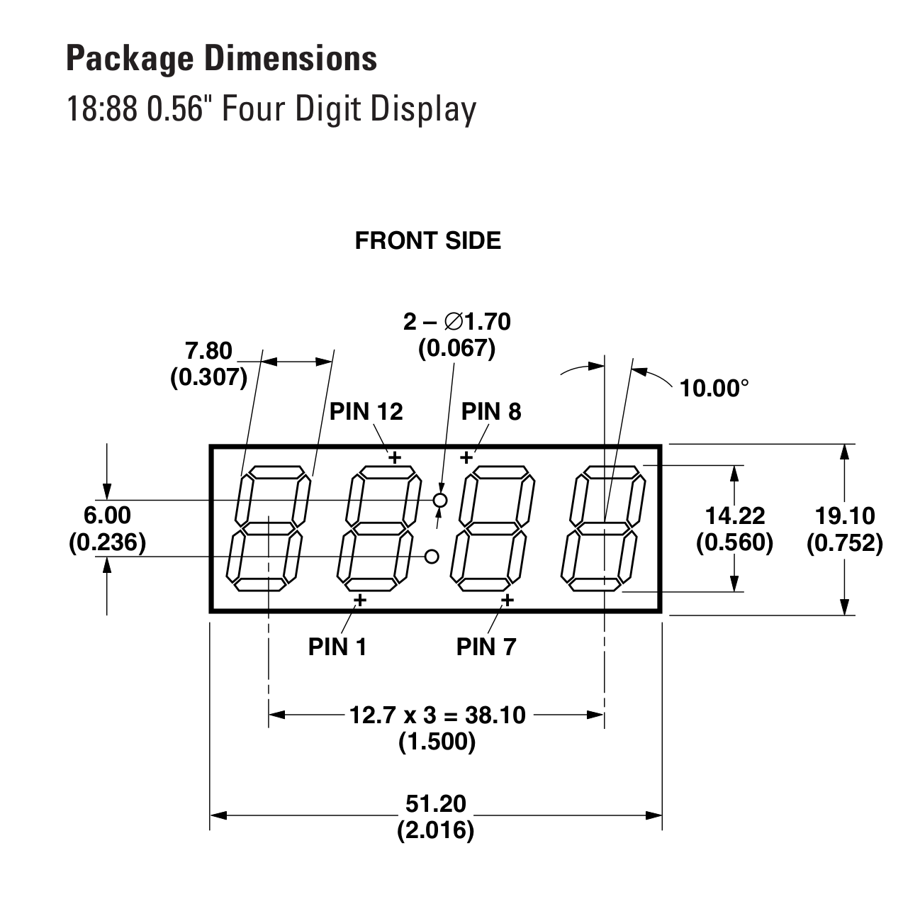
The seeds of this project started when I scored 500 "18:88" common-cathode new-old-stock LED displays on eBay. I think these were intended for clocks (that can't do 24-hour mode, boo). There doesn't seem to be much demand for these displays, so I got them for a song or two, plus shipping.
They came in two fairly large, heavy boxes, which provided impetus for me to convert these boxes into something fancy I could hang on the wall instead of taking up storage space.
Each of these HPDS-B05G displays is a through-hole component with four digits and a colon. The digits are each broken out to their own cathode pin. The segments in all four digits are connected together, so a given position is the same anode pin among all four digits. (The colon gets slightly different treatment, as it becomes a "DP" pin associated with digits 2 and 3, and the first digit only has two of the eight segments.) You're intended to scan through the displays: set all of the segments to a given digit's values, begin draining current through its cathode pin, and cycle through all four digits this way. Do this quickly enough and it appears seamless to our eyes.
You can do this with most microcontrollers, which is perfectly nice and makes it easy enough, given enough pins, to get some nice blink goodness going. But I have done a few other projects with the ISSI IS31FL3733, which is a 12x16 LED current-controlled matrix driver that takes care of 8-bit PWM, overall brightness range, short detection, and other goodies. Having greyscale control of each of the segments is actually quite a lot of fun! So I decided to use this chip for my display panels in this project. I can just give it greyscale values and it makes the magic happen!
The 12x16 (cathodes * anodes) arrangement of the chip aligns fairly well with the 4x8 arrangement of the matrices, letting me pack six displays into a neat panel, using 150 / 192 possible segments. I wired up two parallel "chains" of the HDSP-B05Gs, using CS0:7 for one chain's segments, and CS8:15 for the other. Then I wired together the anodes the other way, using SW0:3, SW4:7, SW8:11. This gives me 150 segments per panel (25 per 4-digit 18:88 panel, with independent colon dots and no decimal points.) If I'd had 8.8.8.8. or 88:88 panels, could've had more segments for "free."
I cranked away on a Very Exciting Spreadsheet for a while. I wanted to have a display of a common aspect ratio, such as 4:3, 3:2, or 16:9, to make mastering the content easier. Measuring the aspect ratio of the physical devices and adding padding and such let me figure out the real size of the panels. With each panel packing 2-wide, 3-high of the 4-digit displays, it turned out to work well to have 6 panels wide, 8 panels tall, for a total digit dimension of 48x24 digits; believe it or not, this ends up being 4:3, with the heights of the digits taken into effect.
I laid out some boards in Eagle, following in the footsteps of some similar boards done previously. This time I made sure to include lots of extra connectivity options--I used "Qwiic," JST-XH x 4, and some panel-edge connectors that can be cross-soldered across multiple boards. The JST-XH connectors ended up carrying the day here.
(Yes, autorouted.)
This chip communicates over the I2C bus and can have one of 16 different addresses. "But there are 48 controllers!" I hear you thinking. Stay tuned for my next project post, about the joys of using multiple I2C buses on the Raspberry Pi 4 with new kernel hooks provided by device tree overlays.
Create an account to leave a comment. Already have an account? Log In.
I2C can easily go past 1MHz if your devices support it; I'm running 800KHz here. The cross-bus sync issues were solved after I took the video with better locking in my application code.
that is quite ridiculous. however the I2C do suffer from having the device to respond and in general cheaper (and simpler) if using shift register approach I mentioned.
I have no idea how you get a 1MHz I2C signal across such a large area though. 20cm of FR4 (PCB) isn't long.
Unless, of course, that you cluster the controllers together and feed the LCD wires a long way, which is also undesired as the voltage will drop across the conductor, although insignificantly.
Hi! Lovely project! I built myself a similar display that I found on hackaday called the 144 7-segment clock. I want to write some code to drive it but I'm struggling with an algorithm that can covert monochrome/binary image on it. How did you do it on yours? Cheers!
(We got talking over email, here's a summary) The hard bit is rendering an overall image in a framebuffer, then assigning an x, y to each segment and sampling the buffer for each segment in order.
Thanks for your help Chris! For anyone else interested in doing this, I found a nice write up here of someone who did something similar and it was a great help. The solution was really straight forward, for some reason I was looking for a complicated solution that didn't actually exist...
https://www.plingboot.com/2017/02/oldskool-demo-on-a-7-segment-display/
only for nerdish artists. "regular" people probably does not get it
Whatever that means.
This project is way cool, and one should _never_ worry what "regular" people like or not.
Really looking forward to details -- love the look of this!
Thanks so much! I've just posted my first project log, more coming soon. Cheers!
I'll be fleshing this out over the coming days. If you are in the DC area, you can come see it in person at VisArts in Rockville, MD, from September 3--October 17.
Become a member to follow this project and never miss any updates
 Arnov Sharma
 Corey Benn
The largest project I had done involving pulling 24 buttons to a Arduino Micro. I used 74HC165Ds and pull in 3 bytes (8 * 3 bits) each loop.
I have also used a SPI display, and being 128*64 you need to push 1KB of data each loop. Even with these constraint it can still manage 80 fps.
Given how you effectively used 288 display modules, you can use maybe 288 of 74HC164 and then wire all the four anodes together (perhaps through power transistors too).
This approach mean however that you need to push 288 bytes EACH time you want to update a digit, which might mean that the digit refresh is slow and the effect (of rapidly switching between four digits) will be very noticeable.
A very unnoticeable 4-digit-display might need to be done with a FPGA. My classes asked me to use a ARTIX-7, which is able to drive the 8 segments quickly enough that no camera can tell that they are rapidly switching on or off. The code got it around 250KHz I think.
Alternatively, just use a immense amount of independent 8 segment displays and push 1152 bytes each cycle (much like the 128*64 screen). However, wiring/soldering them up can be a nightmare.
Both way however require sacrificing grayscale. Unless you want something like 2-bit grayscale & 20 fps. 20 fps is okay, although not a very fast display.
From the video looks like you are doing some decent fps, although the lag between the three chunks is very noticeable (half a second), considering that I2C is a very slow protocol indeed (100KHz). Meanwhile SPI can go up to 1MHz even on a simple device like ATmega32U4.