 Gonzho
Valden Heat Pump Controller v1.x
The Valden Heat Pump controller is an open source platform to precisely control heat pumps. This controller can be used for the automation of newly built Heat Pumps (HPs), as a repair controller for old systems or as control system for performing experiments on refrigeration equipment.
Further details, appendices, fine-tuning options, illustrations, abbreviations, and so on you can find in the permanent repository: https://github.com/openhp/HeatPumpController/ .
Specs
- 12V 0.5A DC power supply,
- 230V output,
- 4 16A relays: Compressor, Hot Circulating Pump (CP) or Air Fan, Cold CP or Air Fan, Crankcase Heater,
- 2 inputs: Hot and cold side refrigerant over/under pressure NC sensors,
- up to 12 temperature (T) sensors, -55..+125 °C range,
- Electronic Expansion Valve (EEV) supported, 6 pin EEV connection: 4 * coils + 2 * 12V,
- automatically turns on/of system when heating required,
- automatic power saving mode,
- built-in protections: cold start, overheat, short-term power loss, power overload, ground loop freeze, compressor protection against liquid and other,
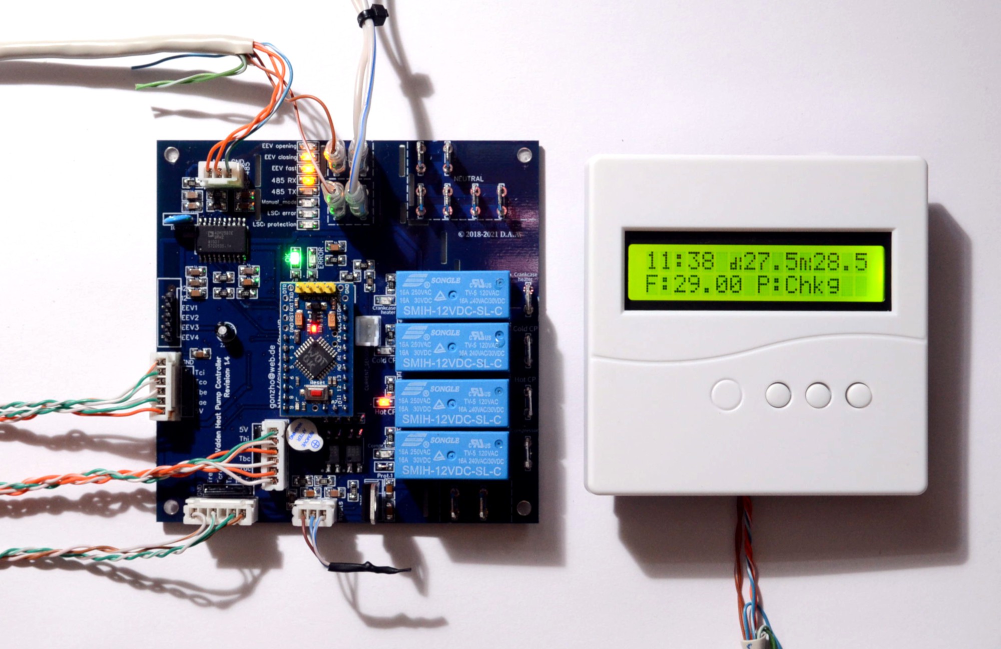
- LED indication,
- control via remote display https://github.com/openhp/Display/ or local Serial (UART 5V).
Refrigeration schemes supported
- Heat Pump (HP) with Electronic Expansion Valve (EEV),
- HP with capillary tube or TXV,
- EEV-only controller.
Installations supported
- Indoor: a house or technical building with an almost stable temperature,
- Outdoor: harsh climatic conditions taken into account. Outdoor HP installations tested down to a minus 32 °C.<br><br>
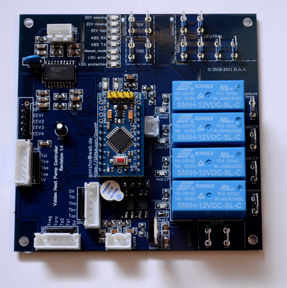
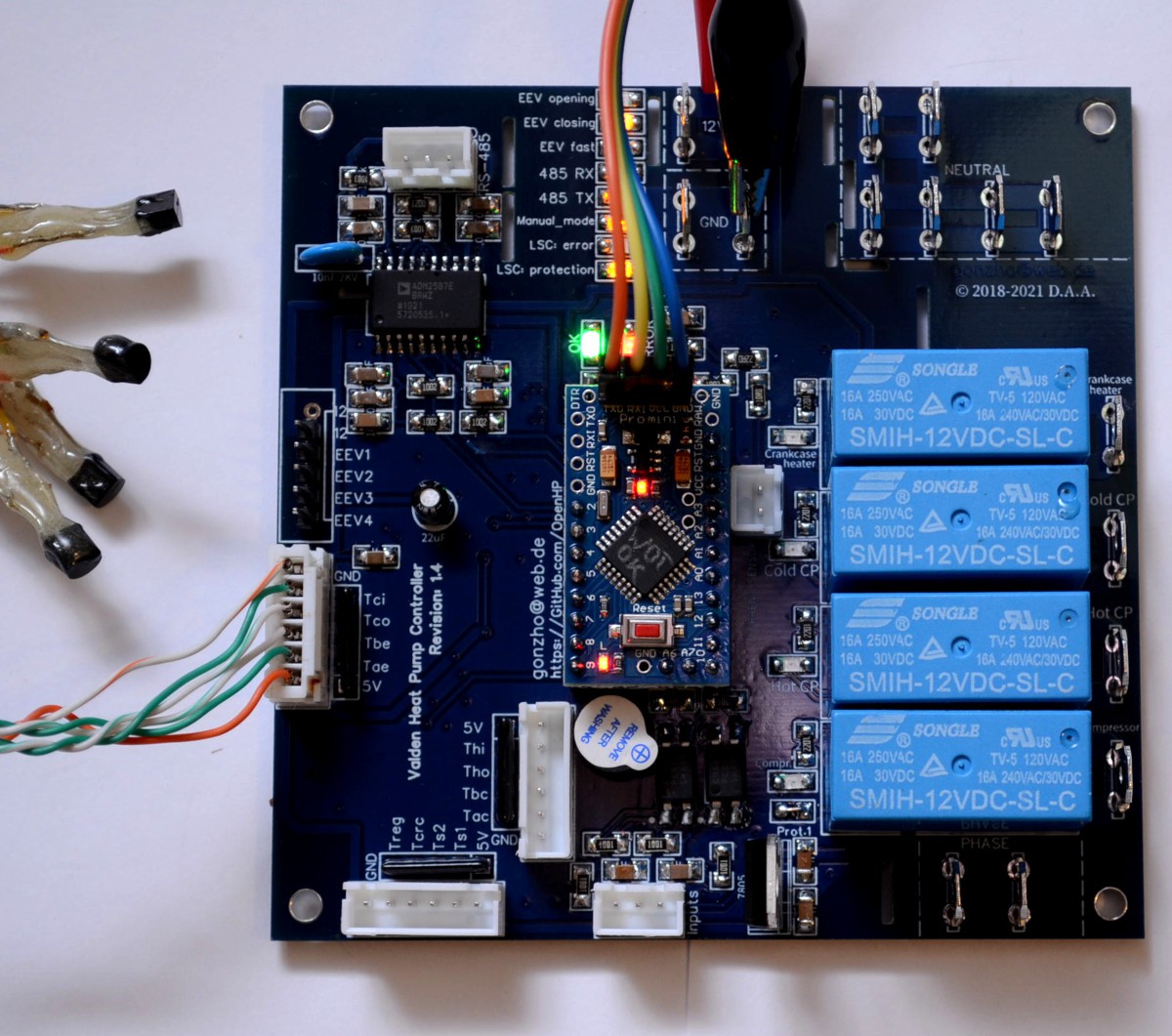
Get your own PCB copy. Assembly.
- download PCB Gerber file here or get your own copy there,
- order electronic components, see BOM (Bill Of Materials) appendix,
- solder electronic components, assembly instructions here.
Firmware upload
This process is the same as for other Arduinos:
- connect USB-> UART converter,
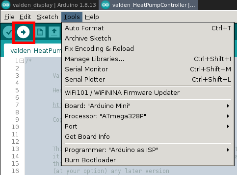
- start Arduino IDE,
- download and open the firmware file,
- select board and MCU in the Tools menu (hint: we are using "mini" board with 328p MCU),
- press the "Upload" button in the interface and "Reset" on the Arduino.
For arduinos with an old bootloader you need to update it. (Tools-> Burn Bootloader).
For successful compilation, you must have "SoftwareSerial", "OneWire" and "DallasTemperature" libraries installed (see Tools -> Manage Libraries).
For the first time it's enough to upload firmware without any tuning. Think of it as of a commercial closed-source controller, where you cannot fine-tune internal options. And any other manual configuration do not required too, just upload firmware. You will see an error LED indication and hear a beep, since no sensors connected to your controller. Follow the next steps.
Self-tests
QA tests are available to test the assembled board.
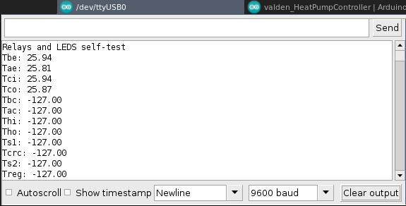
Self-test helps you check relays, indicators, speaker and temperature sensors.
To run a self-tests:
- uncomment this 3 defines in source code header,
```
//#define SELFTEST_RELAYS_LEDS_SPEAKER //speaker and relays QA test, uncomment to enable
//#define SELFTEST_EEV //EEV QA test, uncomment to enable
//#define SELFTEST_T_SENSORS //temperature sensors QA test, uncomment to enable
```
- upload firmware,
- connect 12V power supply,
- disconnect +5V wire from USB-UART converter.
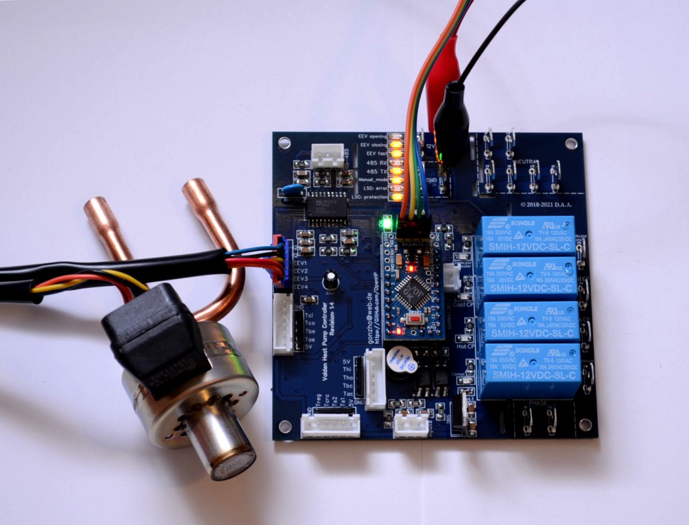
To check EEV connection, you can use a stepper motor. If you are testing a real EEV, it will be closed after the first "beep" and partially opened after the second "beep". If it's not, check if stepper or EEV center pin(s) connected to +12V and try to swap coil-end pins (EEV1..EEV4).
To check temperature sensors connectors crimp one array of sensors. Plug it to all sensor connectors one-by-one and check results in a serial console.
After tests completed, comment 3 self-test defines.
Choose your installation scheme and uncomment one of...
 Tim Bishop
 Red Tuka
 RoGeorge
 Kyle Gabriel