Close
0%
0%

ControlBox

Control your radiant floor heating system (and much more) with Home Assistant

Similar projects worth following
In 2018 we bought a new house. Part of the renovation of this house was to control the heating system in an efficient and reliable way. We decided that it would be nice if we could control our underfloor heating system with Home Assistant. The idea here is that it should be possible to combine the different devices (heatpump, solar collector, wood stove and radiant floor heating) as efficient and smart as possible. When we looked at the hardware available, we quickly realized that we would need a lot of different components to build something like that. Apart from a relatively high price, many of these components work via wifi or other wireless protocols. That was not what we wanted; we wanted something more reliable and, if possible, also cheaper. So we decided to build it ourselves.

In this project I want to share with you what choices we made and why. I also want to show you how you can use the developed hardware. And I want to share the problems we encountered during development

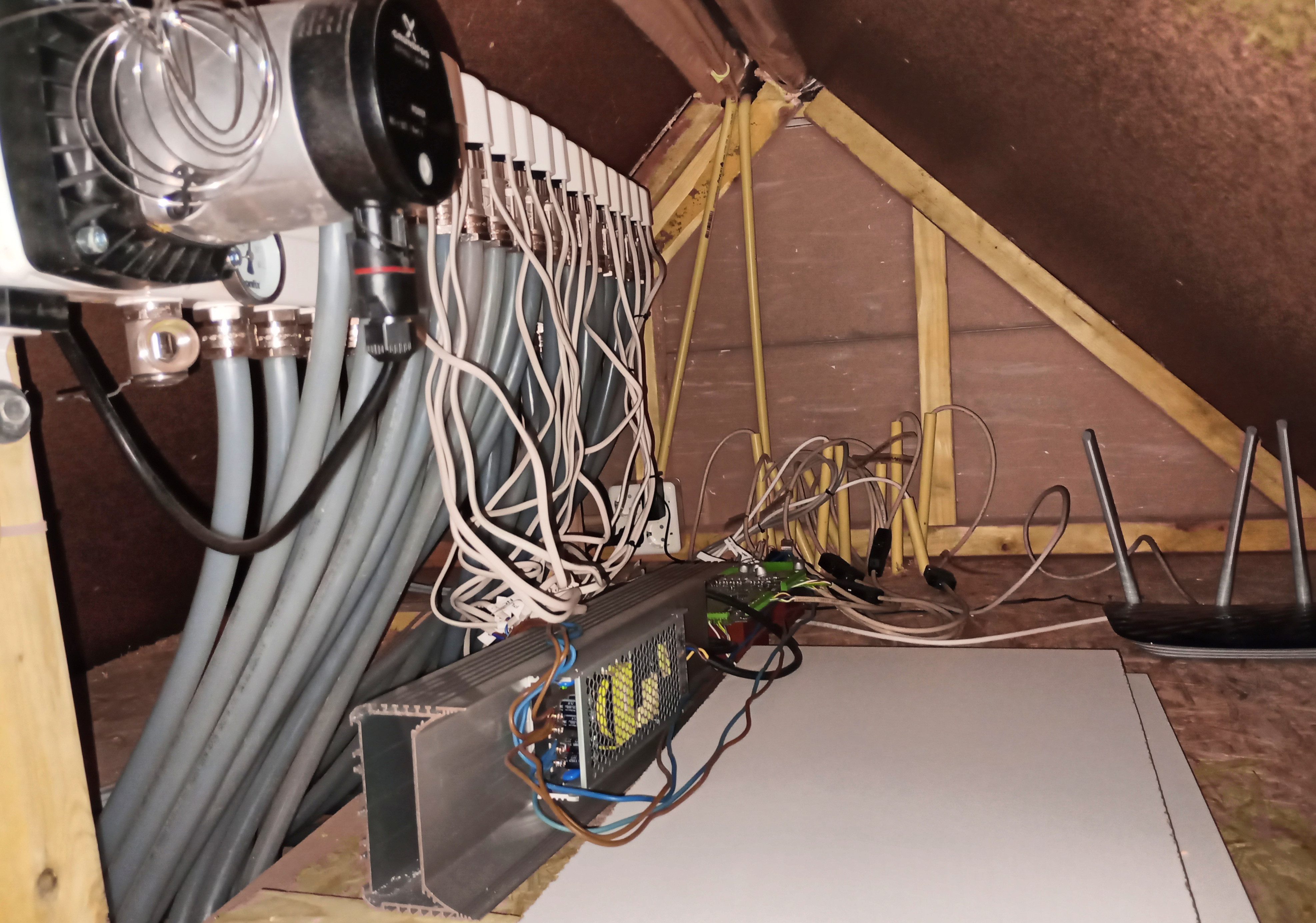
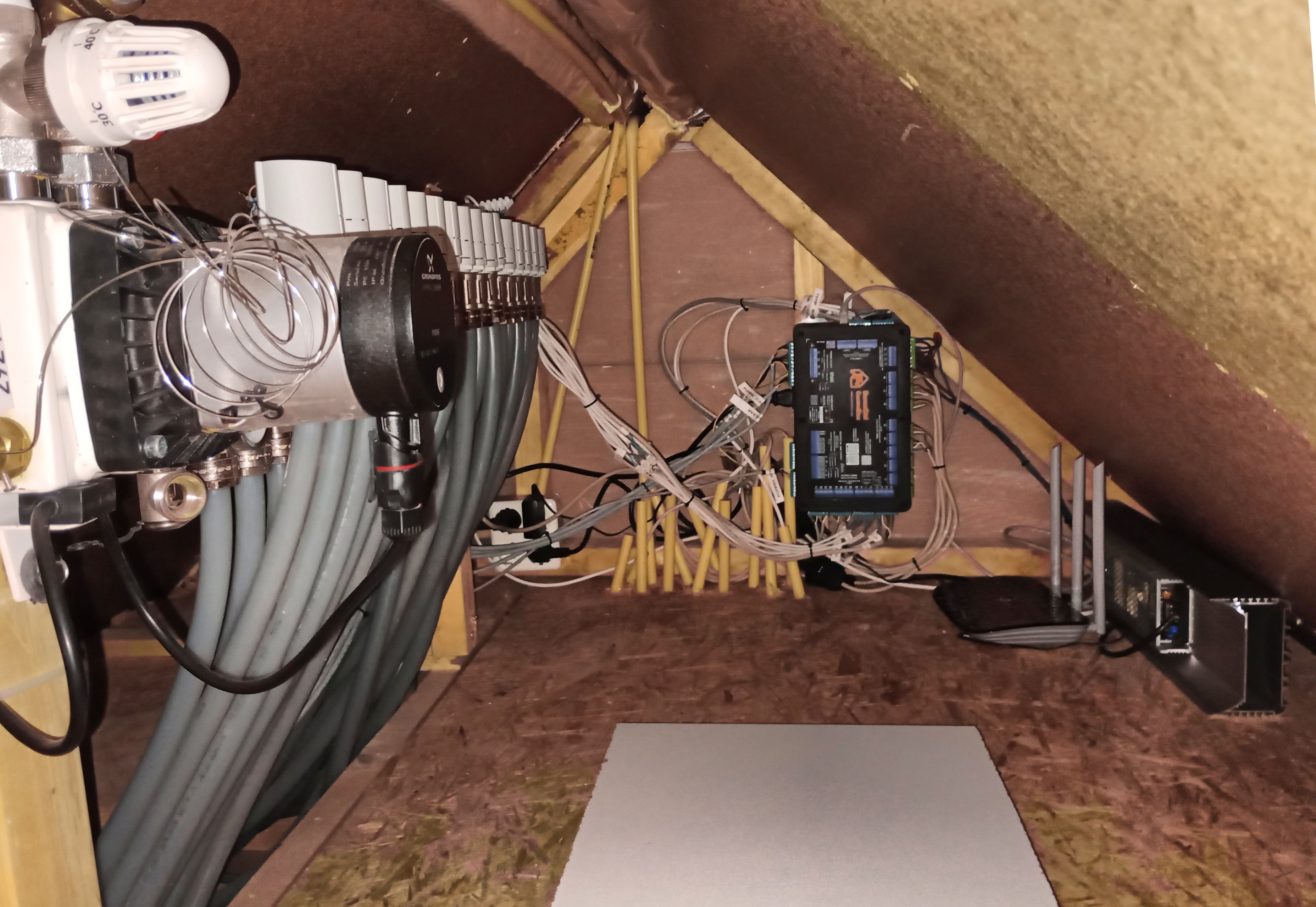
ControlBox is what you need to control hydronic radiant floor heating systems with Home Assistant. It is designed to control thermal valves, hydraulic PWM pumps, and related RFH devices. It can read large numbers of 1-wire temperature sensors over long cables (>6 m). ControlBox also contains 32 LED-strip output channels, providing up to 2 kW output.

Its integration with Home Assistant gives you complete control over the heating peripherals used in your house. With Home Assistant’s advanced scheduling and control features, you can schedule your house’s heating more efficiently, which will help you conserve energy and save money.

The inputs and outputs are considered a core functionality of ControlBox, and they are all provided by hard-wired connections. This ensures maximum reliability so you can always control your radiant floor heating system.

Optimize Your Energy Consumption

With air conditioning and radiant floor heaters on one Home Assistant network, the opportunities for fine-tuning your home’s temperature are almost endless. By installing ControlBox in your home, you can:

  • Implement a software thermostat per room; no additional hardware is required as the user can use the native Home Assistant app on a smartphone to control the temperatures
  • Schedule floor heater systems for automatic pre-heating so rooms are kept comfortable only when required. If the temperature can be lowered up to 3º C over 12 hours per day, this could reduce energy consumption by up to 7% during the winter
  • Automatically switch off the pumps for floor heater systems when no heat is requested to save even more energy
  • More efficient regulation of solar heat collectors by accurately setting the switch-on time with software PID regulator, particularly useful on cold and cloudy days for effectiveness
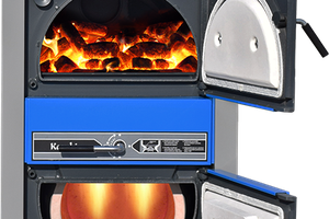
  • Automatically switch off floor heaters in a room when the wood stove or other heat source is on

…and whatever other scenarios you can dream up.

Features & Specifications

ControlBox is powered by a Raspberry 5 4 GB with an NVMe SSD, running Home Assistant. Alternatively, ControlBox can be used with a W32-ETH01 board running ESP32 Home. It has the following IO:

  • Mains voltage input
  • 4x 1.5 A mains voltage output
  • 16x 24 V AC/500 mA output for floor heater valves and 24 V AC peripherals
  • 3x optoisolated GPIO output, 2x optoisolated PWM output
    • Max voltage: 24 V DC. Pullup to 5 V DC or 12 V DC can be configured via a jumper or external supply
  • 3x optoisolated GPIO input. Voltage: 5-24 V DC, max current 16 mA
  • 4x LED power input
    • Max voltage: 24 V DC, max current: 20 A per pin. Total power capacity 2 kW
  • 32x PWM controlled outputs for LED strips. Max. voltage: 24 V DC, max current 10 A per connector
    • Configurable PWM frequency, default 200 Hz
  • 2 channels to 1-Wire line drivers
    • Each connector: 3x data pin, 2 x 5 V pin, 3x GND pin
    • Data line voltage: 5 V, max. 20 mA (parasitic mode allowed)
    • Power line max. 500 mA / 5 V for both channels simultaneously
  • Half-duplex RS485 communication bus (5 V)
  • 433 Mhz superheterodyne transmitter & receiver modules for communication with wireless peripherals like 'ClickOnClickOff'

Warmteverliezenberekening.ods

Heat dissipation calculation (dutch) based uppn the example of Steven van Lier

spreadsheet - 270.46 kB - 02/26/2025 at 15:25

Download

HeatingSchematic_compact.svg

Schematic overview of the heating installation

svg+xml - 205.13 kB - 02/26/2025 at 15:16

Preview

ControlBox.pdf

Specifications of the ControlBox

Adobe Portable Document Format - 1.02 MB - 12/07/2024 at 13:57

Preview

  • Using the ControlBox to for smart heating control

    Anton Verburg02/26/2025 at 15:54 0 comments

    Its nice to have a high-quality control device, but its even nicer to use it to control your house. In this log I want to showcase how we use the ControlBox in our own house.

    During the renovation of our house, we had to supply a calculation of the heat dissipation in our house to apply for the permits. I found a very useful example of such a calculation, made by Steven van Lier. The original calculation can still be found here. We converted this calculation to represent our own case, and we added some calculations to estimate what kind of heat sources we would need in different use cases to heat our house. It gave us a nice overview of what is required, and why. Our own variant of this calculation is available here.

    Finally I created a schematic to supply an overview of how the different heat-supplying and heat-buffering devices in our house are inter-connected. The schematic is available here.

    I think we did some less-conventional things to reduce energy consumption.

    • We use a small heat-pump water boiler (input power 400 Watt) to supply heated tap water.
    • We have a heat exchange between the tap water boiler and the two hot-water buffer boilers in the attic.
    • We can provide heat from the heat-pump to those buffer boilers, but we can also bring back heat from the buffer boilers to the tap water.
    • As we also have a vacuum-tube heat collector on the roof of the house, we are able to switch the (electricity consuming) heat pump off in summer time; in this period hot water is provided by the heat collector.
    • In winter time, the heat transfer will be directed in the other direction; the heat pump and the heat collector will both heat the hot water buffers.
    • Using those hot-water buffers we are able to lower the temperature at night, while we still have comfortable temperatures when the day starts.
    • Because the heat pump we use is a air-to-water heat pump, we also use it to ventilate our house.  By supplying the heat pump with the relative warm ventilation airflow, the efficiency of the heat pump increases.

    In order to regulate & coordinate all those tasks, the ControlBox is used. The ControlBox will:

    • Read all temperature sensors tx.
    • Switch valve A, B and C. Use 24VAC for safety reasons
    • Switch the motors on floor heater distribution group
    • Control the flow of pump p1 and p4 via PWM signal.
    • Switch all pumps on/off
    • Check via internet outdoor temperature & weather forecast

    With the input of the temperature sensors the ControlBox can:

    • Verify if there is a request for heat on 1st floor (living room/kitchen) is (t14).
    • Verify if there is a request for heat on the 2nd floor (t13).
    • Calculate the amount of heat dissipation of the house (t8 en t9)
    • Check if wood stove is burning:
      t15 will go high: switch off floor heating. If delta between t15 and t16 gets too large switch p1 on.
    • Balance and regulate the heat in the heat-buffer boiler, tap water boiler and solar collector (t1 to t7 , t10 to t12 and t18).

    With pump p3 and valve a, b and c heat can be exchanged from the heat buffers to the tap water boiler or vice versa. Direction of the heat flow can be regulated with valve a and c. In winter time, the heat buffers can be heated by the heat collector, the heat pump and the wood stove. In summer time, the heat collectors can heat also the tap water, and the heat pump can be left off.

    Pump p4 brings heat from the heatcollector to the buffer boiler. The PWM pump is regulated with a PID controller
    that regulates the delta between t1 and t18.  The switch-on moment is defined by monitoring the cumulative amount
    of energy that has been harvested by electrical solar panels since the last time it was switched off.

    Pump p2 en p5 are switched off when not in use .

    Heat transfer from wood stove to heat buffer boilers will basically happen via natural circulation (thermosyphon).
    This will ensure a safe flow independent from pumps, hardware or software (ensuring safety).
    If temperature of t15 gets too high, pump p1 can be switched on to cool down the...

    Read more »

  • Typical design decissions

    Anton Verburg12/07/2024 at 16:19 0 comments

    So what decisions did I make during the design of the ControlBox, and why?


    Well, when building hardware a lot of decisions have to be made. During the development of this piece of hardware, I always tried to choose the most-robust option. So here we go:

    • For mains outputs, we selected panasonic AQG22105 solid state relays with integrated snubber circuit and zero-crossing detection.
      • The disadvantages of electromechanical relays are their slow response
        time, high maintenance, and limited functionality. They are prone to wear and tear, contact erosion, and mechanical failures. So we wanted to use solid state relays.
      • According to the datasheet it should be able to supply up to 2A. But when testing the fuses, it was proven that a fast fuse of 2A would break the switch, so we decided to limit the current to 1.5A.
      • Utilizing the integrated snubber circuit and zero-cross detection, unexpected current peaks and other harmful signals are omitted.
    • For the 24VAC outputs, I had the following reasons:

      • This 24VAC is typically consumed by installation devices in an environment where leakage is possible. Think about the thermal wax valves of the radiant floor heating, but also 24VAC zone valves exist. The reason why these devices do not work on mains power, is safety. Imagine what happens if water is leaking over your 230VAC powered devices....

      • 24VAC thermal wax valves are very common, and can be bought anywhere on the world.
      • An unforeseen benefit of using the 24VAC devices is the connector space on the board; because the lower voltage, a smaller distance between the pins is allowed. And that allows denser connectors, so that we can put more IO on a smaller footprint.

      • Switches for 24AC are cheaper than those for 230VAC as well.
      • During my search for controlling the thermal wax valves I also saw that you can control them with 24VDC. But when I continued my search, I concluded that a 24VDC power supply is always more expensive than an on-board mains-to-24AC transformer.

    • Reading the 1-wire (temperature) sensors happens via two DS2482S-100 drivers. They are robust, and they have a function that enables to provide parasitic sensors with power via a push-up FET.
    • You might have asked yourself the question:
      • Why a RS482 half duplex port?
        The reason is simple; I have seen several devices utilizing such a port. An example is our own GoodWe solar panel transformer, or the Hewalex heat pump. And as our idea was to combine all available hardware via Home Assitant, in order to make the smartest possible decisions, we needed an RS485 port.
      • Why 2kW LED strip outputs?
        Just because it's fun. We had the idea to provide some kind of 'anti-theft' light around our house. Because we where preparing the renovation, we had the freedom to plan it like we preferred. And because I had done some nice projects with LED lights before, I thought 'well, it would be nice to put that around our house too'. And that's why I integrated it. When bringing this device to the public, I have considered to leave it out. But as the component costs are not that large compared to the rest of the unit, they are still there.
      • Why the RPi 5 + NVMe solid state disk?
        The raspberry pi is a common used hardware platform for Home Assistant, and can be easily installed with Home Assistant Operating System. This will give you all benefits of Home Assistant, including automatic system maintenance via the supervisor, and easy installation of the HACS. In future, the raspberry pi can easily be swapped for a faster or better single-board computer. The only disadvantage of the raspberry Pi till now was that it runs from an SD card. As internally Home Assistant uses database software, this is not a stable solution. But from version 5 this is solved; the pi can now run on a fast NVMe solid state disk, that contains a good controller to prevent the disk from corruption.
      • Why do you prefer wired connections? The newest wireless protocols are good, isn't it?
        Well, the newer protocols are getting better. But I have seen too...
    Read more »

View all 2 project logs

Enjoy this project?

Share

Discussions

Similar Projects

Does this project spark your interest?

Become a member to follow this project and never miss any updates