agp.cooper
-
Speaker Volume from Two Transistors
11/17/2016 at 07:06 • 0 commentsSpeaker Volume from Two Transistors
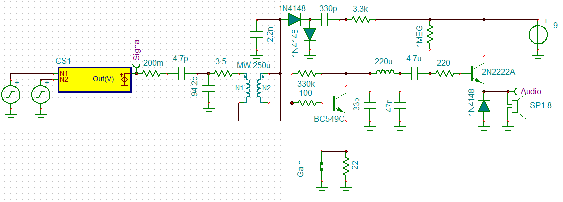
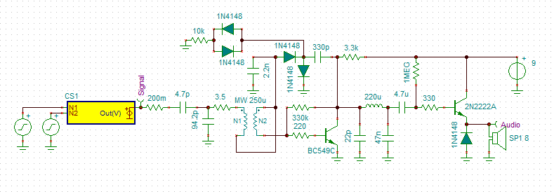
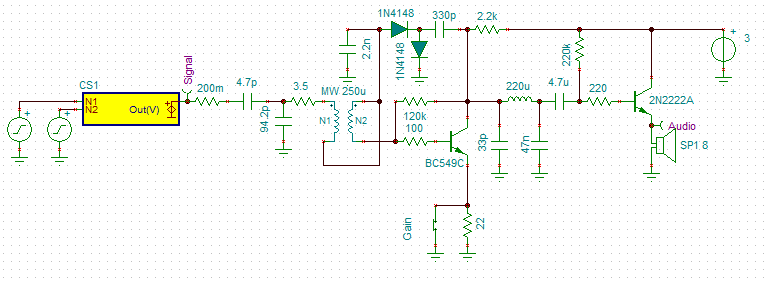
It seemed to be within reach so I had a go. Here is my design:
![]()
The idea behind the "gain" switch is to reduce the gain (open) for loud station in order to reduce distortion.
Results
Works well. Volume out of a small 5w speaker was quite adequate for home use.
Voice was fine but music was badly distorted. Reducing the gain did not help.
A single sided class B audio amplifier is not going to help either.
I think the receiver is too selective for music.
I should have stayed with the 3 turn coupling coil rather than changing to 2 turns.
Boxing It Up
I think I am ready to "box up" this receiver and call it done.
Medium Wave PCB Coils
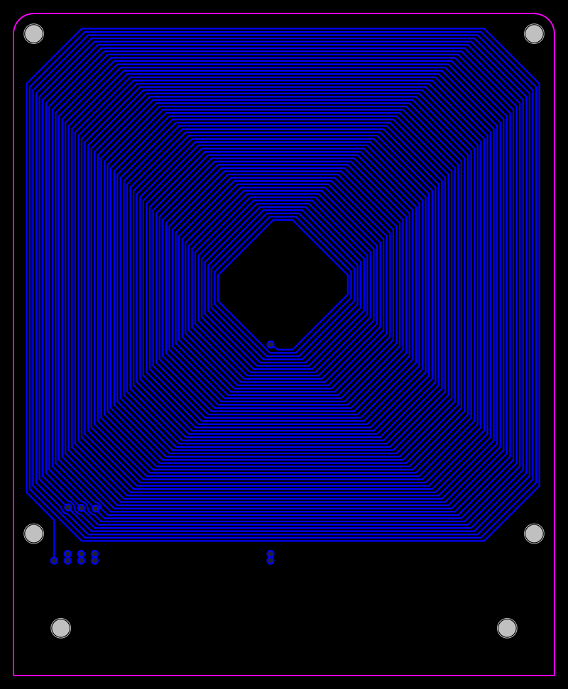
I had a go at designing a MW PCB coil:
![]()
Unfortunately the Q of these coil is quite low (~40 for 1 Oz copper and ~60 for 2 oz copper) but the self resonance is about 1.8 MHz.
I suspect that to use these coils a regenerative design may be required.
Some More Adjustments
Decided to rewind the coupling coil from 2 turns to 4 turns.
Louder (expected), less selective (but still too selective) and much less distortion.
For MW/AM I think 6 or 8 turns may be better.
The gain switch resistor may need to be increased from 22R to 33R or 47R.
Boxing Up The Receiver
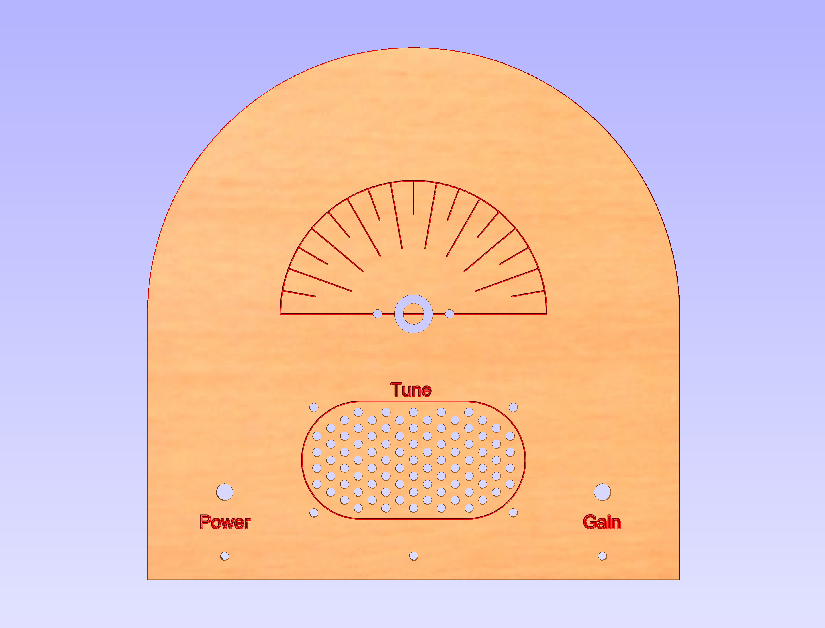
I made up a front panel (done):
![]()
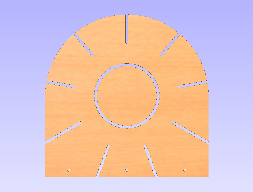
And a matching new coil former for 0.63 mm diameter wire (to be completed):
![]()
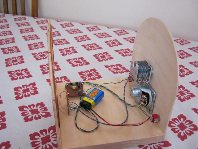
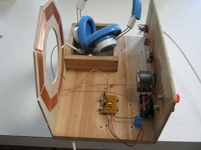
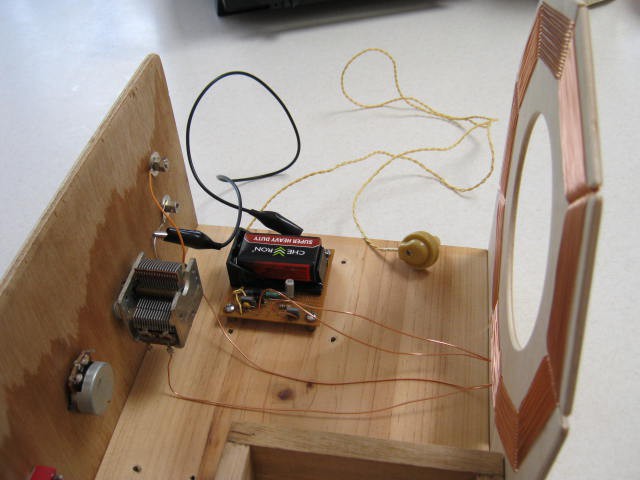
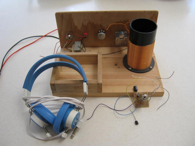
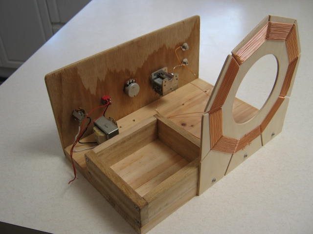
Here is the finished project:
![]()
And:
![]()
Problems
Several problems with the set:
- The coil has too many turns (all the stations are on the high frequency side of the tuning range (must have been a calculation error for the required number of turns).
- The receiver is a but too loud and therefore consumes too much current for a 9v battery.
- Distortion is better but still too much.
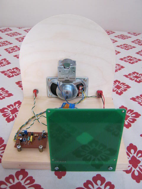
I swapped out the coil for a PCB version and it works but nowhere near as loud:
![]()
The PCB coil has very low Q (about 44) but selectivity is okay in this application. The reflex has some regeneration.
Distortion is much better with this coil.
If I want more volume I will have to swap out the 9v battery and use some AAs (i.e. 3v) as they will last longer. I will also have to change some resistor values.
Distortion
The distortion makes this receiver disappointing. The problem is not with the Class B audio amplifier as the problem exists with a crystal earpiece.
I originally thought that the problem was because the receiver was too selective but the problem persists even with the low Q coil.
Reassessing the receiver
Although the receiver is called a Reflex and the RF is decoded by the diode network and re-amplified by the first transistor it is not quite that simple. It is also regenerative because it does matter which way the coupling coil is linked up.
The diode detector is acting as a square law detector with unit gain around 100 uV to 1 mv because the audio voltage increases as a square of the input voltage. But I think it is also regulating the regenerative feedback. I am starting to think that in the presence of a signal the receiver goes into oscillation (or the level of oscillation increases) and demodulation is more mixing than square law detection. Particularly as the diode network is unbiased.
As per the "synchronous detector" I built, if over-driven (i.e. too much feedback), the demodulation becomes chaotic (i.e. distorted). This chaotic behaviour is probably equivalent to parasitic oscillation.
So I suspect the distortion is actually parasitic oscillation. The solution may be to increase the value of the 100R base resistor to say 220R or higher.
Tried the 220R resistor improved but not fixed, 330R improves a little more but reduces sensitivity. It seems the remaining distortion is for strong stations and mostly in the Class B amplifier. Is it the Class B or parasitic oscillation? Perhaps I should increase the base for the Class B as well.
Well, 330R works a bit better but using the oscilloscope shows the audio saturating (may be going into oscillation?) in the first stage. The saturation shows up as an exponential spike on the audio. So the only option now is the gain control "emitter" resistor. Tried a couple of values but the 22R seems best for the PCB coil. Still the gain control does not work exactly as intended on strong stations so I would drop it in the next revision.
So now the audio is fair for most stations except the strongest and for those. the gain control pulls them down and tames them (well sort of).
Given the square law response of the detector this is probably about as good as can be expected without automatic gain control.
One last try, I though the 33 pF "collector capacitor" may be partially to blame so I increased the value to 47 pF. The reason for this is that another experimenter stated that a lower RF choke values increase selectivity while a larger RF choke value increase volume. I have not found the volume argument to be true but the selectivity claim I cannot dismiss and I think it may be right. The larger capacitor was expected to decrease gain and reduce the likelihood of oscillation. Yes it reduced the volume but the distortion was still there.
I am back to the need for an AGC.
Cracking the Distortion Problem
Hard to leave this thing alone but I have cracked the distortion problem (without resorting to a proper AGC).
Since the source of the distortion was an exponential like audio spike from the detector stage, I decided to a a soft limiter:
![]()
The 10k resistor seems to be a reasonable start point. The limiter seems to delay the onset of oscillation as well (if I remove the 22pF capacitor).
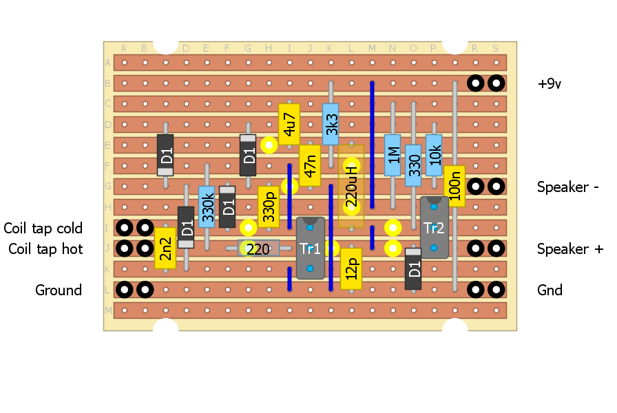
Here is the strip-board design:
![]()
Results
Gain is down but distortion is absent (Yeah!). Listening to music is now quite reasonable. Swapping out the PCB coil for the over-wound and over coupled spider coil, distortion is still a problem but much less, but this may be partially due to the high Q or very narrow bandwidth of the coil.
So rewinding the coil and reducing the coupling should workout well.
One Last Consideration
Measuring the (average) current consumption (~4 mA) under average volume but low distortion suggest that the Audio Amplifier is operating in Class A mode (rather than Class B) as the quiescent current is 2 mA. Increasing the quiescent current to say 4 mA would push the Class A to Class B crossover distortion to high volume levels.
Easy to do, replace the 1M resistor with a 470k resistor. Worth a try as current consumption still quite low (<10 mA).
Success
Replace the 1M resistor with a 470k resistor and the results were good except for the strongest station. Okay try a 330k resistor and all good. Disabled the clipping and all good except for the strongest stations. So okay, the main problem was the audio amplifier bottoming out. So I have removed the clipper circuity.
Now I could have gone a 2 transistor audio amplifier or a transformer audio amplifier straight up but I wanted to limit the radio to 2 transistors all up and no transformer.
One option is a bias switch for the strong stations. That way, low current consumption for weak stations and higher current consumption for stronger stations.
Another option is an audio input attenuator for strong stations.
Although the clipper works the cost is gain (no surprise).
Probably the best option is to adjust the bias (quiescent current for the audio amplifier) for your set up and let it be.
If current consumption is too high (for a reasonable life for a 9v battery) then reconfigure the circuit for a 3v power supply.
The clipper would be a useful addition if a better (i.e. higher gain) audio amplifier is used.
All in all the current set up and sound quality (for AM) is quite pleasing. Just need to build another spider coil which covers the AM band properly and perhaps less coupling.
Oscillation
I have mentioned that the reflex circuit is a bit more complex than it first appears.
One is that it is regenerative (i.e. it matters which way the coupling coli is connected).
The second is that on each side of the station, audio beats (whistles) can be heard. So it is actually a synchronous receiver. The beats disappear when the oscillation locks onto the station.
The beats are not so obvious with the PCB coil but they are there.
The whistles tell you a station is near!
3 volt version
Swapped out some resistors and configured the receiver for 3 volts. Two AA batteries will last longer than a 9v battery and is cheaper to replace.
Surprisingly the gain was higher and all the whistles are gone.
Some distortion with the strongest station but otherwise all good.
Just need a new coil that covers the MW spectrum properly.
Final Project
Rewound the coil for 32 turns and 8 turns. Volume is good and selectivity is good enough (not great). No whistles but synchronisation is pretty obvious when you know what to hear for.
Increased the audio quiescent bias from 6 mA 12 mA (to adjust for the higher volume of the new coil) by reducing the bias resistor from 100k to 47k. Only the strongest station still suffers distortion. Really I should add another transistor to make a conventional push-pull audio amplifier but then it would be a three transistor design rather than a two transistor design! Here are some images:
![]()
And:
![]()
So all good. Unlikely to come back to this project.
Simple Audio Amplifier
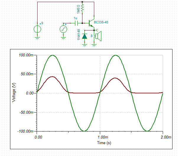
If you drop the supply voltage and don't mine high current draw this one works:
![]()
AlanX
-
Yet Another Simple MW Receiver
11/12/2016 at 23:14 • 0 commentsAnother MW Autodyne Receiver
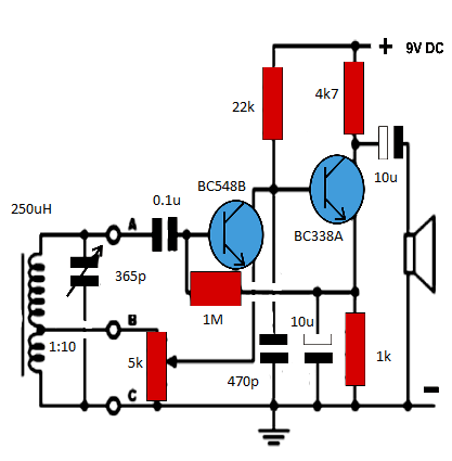
I knocked up this circuit as it claims so much (there is a version with a speaker transformer that claims loud speaker performance from two transistors) and is so simple:
![]()
The regeneration/gain control is a little strange (the gain will go down and then back up, as the regeneration feedback increases) but in practice it works very well.
Actually better than the reflex! The only strange thing was that from time to time it just stops by itself and I have to wind the regeneration to zero and back up again (or power off)?! It may be C4 playing games? The circuit probably needs a bypass capacitor from the collector of T2 to ground as well.
For transistors I just used the BC548B.
There is another version of this receiver with different component values:
http://www.homemade-circuits.com/2012/10/simplest-am-radio-receiver-with-speaker.html
I used his image but added the component values:
![]()
This circuit will work much better with an audio transformer.
The problem is that the audio transformers are the crappy small ones of the expensive (but still crappy) big ones.
So I decided to use a small potted AC transformer.
Found a PCB mount 0.3VA 220v to 18v job (equal to 1200 ohm to 8 ohm) that will be perfect for these radios for A$8/each.
The Reflex Receiver
I have been analysing this circuit and I am not that impressed (any more):
A lot of gain has been lost due to the emitter LCR network.![]()
I should look at alternate biasing methods.
The Three Transistor Design
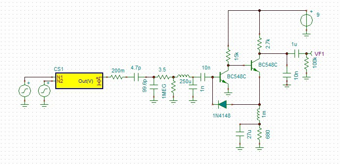
My pre-amp buffer was a dog! Here is an updated design:![]()
I have changed the biasing arrangements and added a 1k resistor to the base to stop oscillation (as a colpitts oscillator).![]()
I am am now looking at this reflex:
I will have to model it to see how it compares. Here is the model:![]()
![]()
The 33 mH choke is a bit of over the top, 1m works just as well.
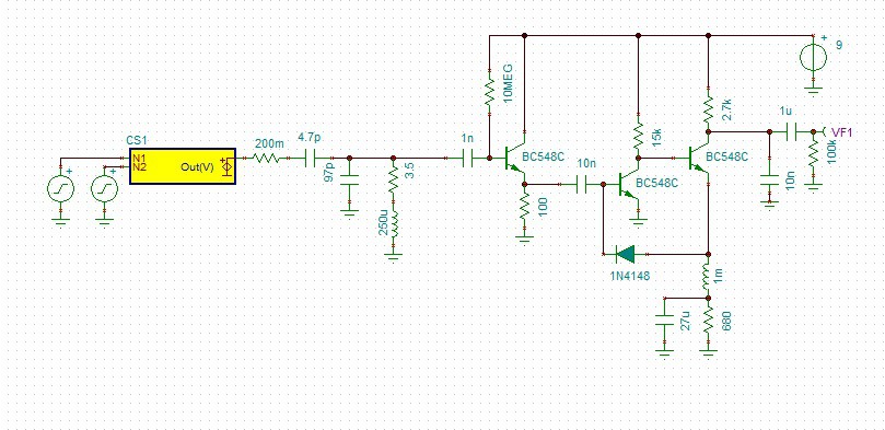
I reworked the component values and got a big improvement in the simulator (x10):
![]()
A One Transistor Reflex
Modelling a one transistor reflex.
There are a number of schematics on the Internet.
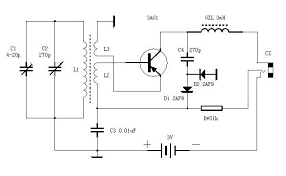
Here is a very simple one (the 636):
![]()
And a video from the Internet:
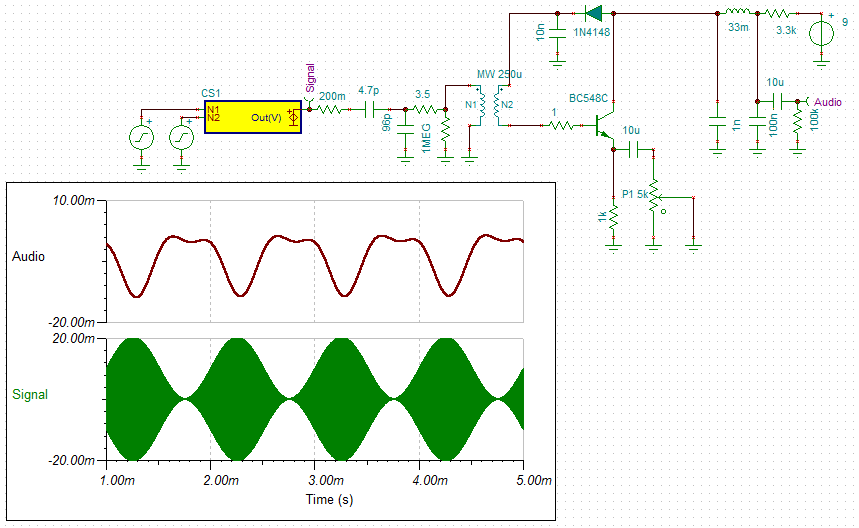
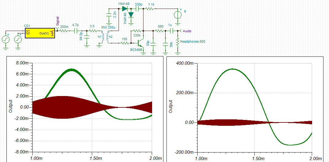
Here is my simulation of my version:
![]()
A number of changes were made:
- Modified for 9v and crystal ear-piece output.
- Added a 1k base resistor to stop "Colpitts oscillation".
The schematic consists of:
- On the far left, a the signal generator (before the the signal probe).
- Then the short wire antenna model.
- Then the tuning coil and tap at 10%.
- The the 636 circuit.
Analysis:
- The left analysis is of a 1 mv 1 Mhz signal modulated by a 1 Khz audio signal.
- The audio shows a square law distorted audio output of 6 mv (a gain of x3).
- The right analysis is of a 10 mv 1 Mhz signal modulated by a 1 Khz audio signal.
- The audio shows a square law distorted audio output of 900 mv (a gain of 45).
Replacing the 1 mH inductor with a 1k resistor, this reduced the gain by a factor of 3.
![]()
Increasing the tuning coil tap to 20% kills the tuning coil Q.
Here is another version that uses a higher coupling tap but uses regeneration (L3) to "fix" the Q (but L2 looks to be the wrong way?):
![]()
(source: http://electronicdesign.com/analog/rediscover-truly-tunable-hall-network)
More Optimisations on the 636 Reflex
Optimisations in a simulator can be false!
So the results should be reviewed to determine if they are reasonable.
I have had overly unrealistic performance from a simulator for my diode transistor NAND gates (at least 10x better than reality).
So I am getting very good improvements with the 636 reflex receiver but I think they are believable!
One thing I noticed with Rick Anderson's receiver above is that the 0.001uF capacitor from the collector of transistor 1 to ground was necessary.
At first I glance it appeared to be part of the low pass pi filter.
It was a little strange as it bypasses RF to ground in competition with the diode.
Reducing the value 10 fold improved performance (10 fold) but total removal killed the circuit?
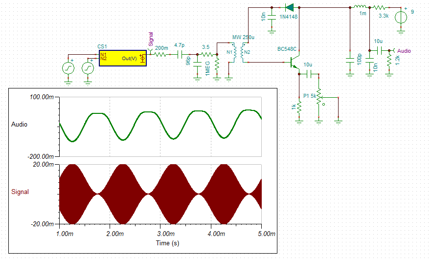
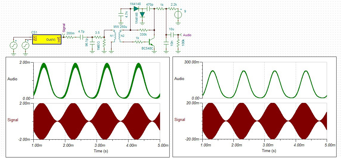
So I added this the the 636 reflex and got a huge improvement:
![]()
I also set the audio load to that of a transistor audio amplifier.
At higher signal levels (10mV RF) the audio is quite distorted.
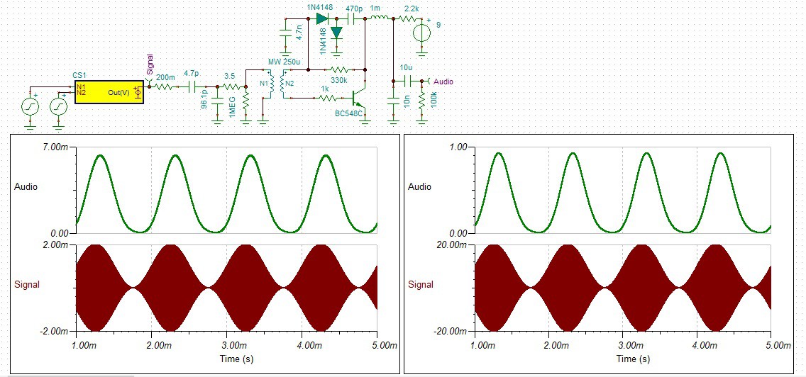
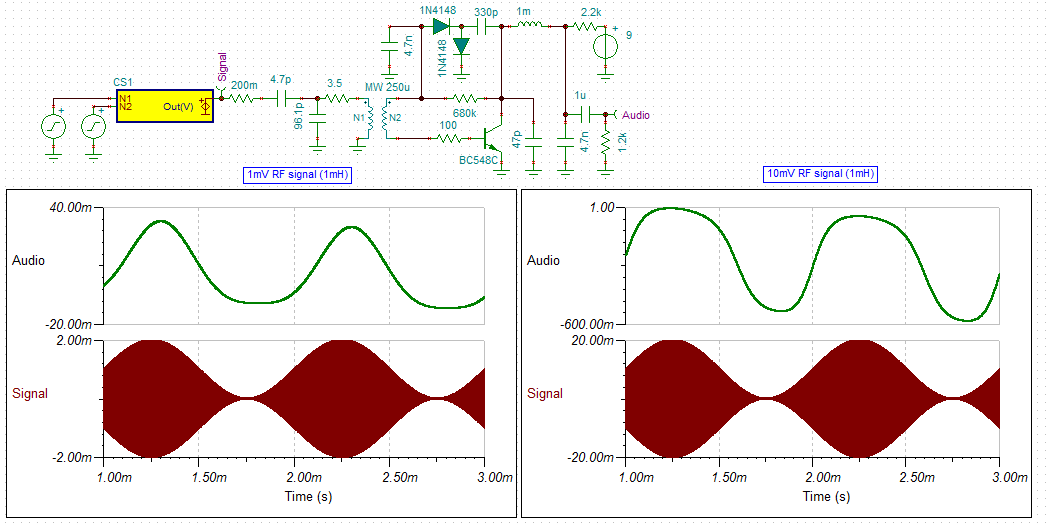
A higher audio load impedance helps:
![]()
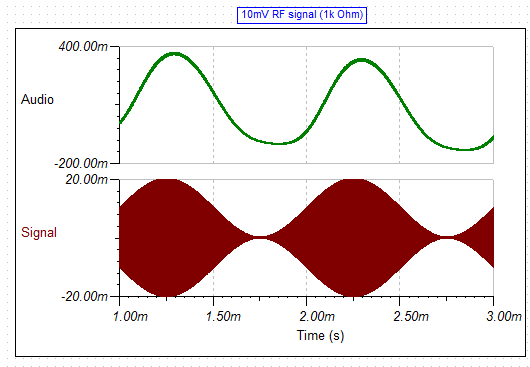
If you accept lower gain replacing the 1 mH choke with a 1k resistor also helps:
![]()
There is still some RF in the audio signal so a 4.7 nF bypass capacitor across the 1.2k audio load would help.
Here is the strip-board layout:
![]()
It Works
It works brilliantly!
![]()
Actually it is too loud for my crystal ear-piece.
On the oscilloscope the audio was clipping at 3v pp!
When I powered it up I thought it was not working because I could not hear any static.
The transistor voltage checked out but I could not make it oscillate by touching it anywhere.
Attached the coupling coil connections (no antenna) and it amazed me.
The selectivity was not great but good enough (as per the simulation).
There is so much gain that a lower tap for greater selectivity would be of value else a regeneration coil.
This circuit with a speaker transformer would definitely work as a loud speaker radio.
Update
I have reworked the schematic for a 600 ohm set of headphones:
![]()
The current consumption is still only 3.2 mA.
I also swapped out the RF choke for a resistor (accepted the big gain drop!) and reduced the coupling coil turns from three to two, in order to increase the selectivity.
It works quite well (not as loud) but very selective (you get a surprise when with a small adjustment a station comes in quite strongly).
I have found all the Perth MW/AM stations (no antenna but I did have to rotate the set for the signal direction).
I will make up a new front panel for the receiver and bring this project to a close.
Here is the as built schematic:
![]()
If you really want some gain replace:
- the 1.1k resistor with a 3.3k resistor, and
- the 560 ohm resistor with a 220 uH RF choke.
You will need a volume control if you do this!
A Transistor Speaker Driver
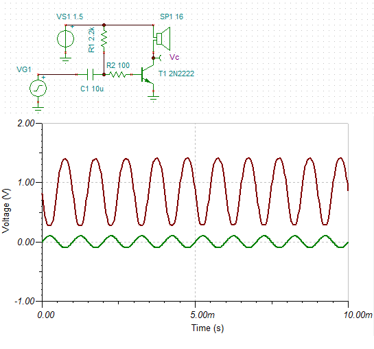
In theory a Class B amplifier should work fine for this receiver. Here is my design:
![]()
The base resistor was chosen for a quiescent current is about 1mA.
The value depends on the transistor type so check you circuit in operation.
The diode recirculates and inductive currents from the speaker (not really necessary).
The input impedance is between 5k and 15k depending on the transistor gain.
Testing the Audio Amplifier
Bread-boarded the design and it "motorboated" (i.e. sounds like a "motorboat").
The usual diagnosis for this is audio feedback through the power supply.
Okay, add a 120R resistor and a 100uF capacitor to the power supply. No.
Noted that hand capacitance influenced/stopped the motorboat.
So it must be RF feedback. Added a 220R resistor to the transistor base and all good.
The quiescent current was about 2 mA using a 1 M bias resistor and a 2N2222A.
I used the 2N2222A as I have a heap and they are rated at 500 mA DC.
![]()
I have made three other changes:
- Reduced the power supply to 3v (reduces gain)
- Linked the transformer as a single tapped coil (reduces gain?)
- Add a gain switch (for strong stations) but a variable 100R potentiometer (if you can get one) would work better.
Because of the gain reductions the RF choke version may be a better circuit to use:
![]()
Printed Circuit MW Coil
Winding coils is not as exciting as it used to be!
Here is a printed circuit board MW coil:
![]()
The coil is single sided and has 64 turns total. Taps at 4, 6 and 8 turns:
- Inductance is about 224 uH for 64 turns and the Q a low 38 for 1 oz copper PCB.
- Self resonant frequency of 1.75 MHz.
- If the coil is ground at the 8th turn then the coupling turns can be 2, 4 or 8 turns to 56 turns (163 uH).
- If the coil is ground at the 6th turn then the coupling turns can be 2 or 6 turns to 58 turns (177 uH).
- If the coil is ground at the 4th turn then the inductance is 192 uH.
Increasing the copper weight (2 oz) costs but the Q increases to 58.
AlanX
-
Receiver Improvements
11/12/2016 at 22:53 • 0 commentsReceiver Improvements
I modelled the Reflex (I could not get the coil tap to work properly but I got a capacitive tap to work):
![]()
The input impedance to the first stage is dominated by the diode impedance (~70 ohm).
This explains the 1:10 tap of the original circuit.
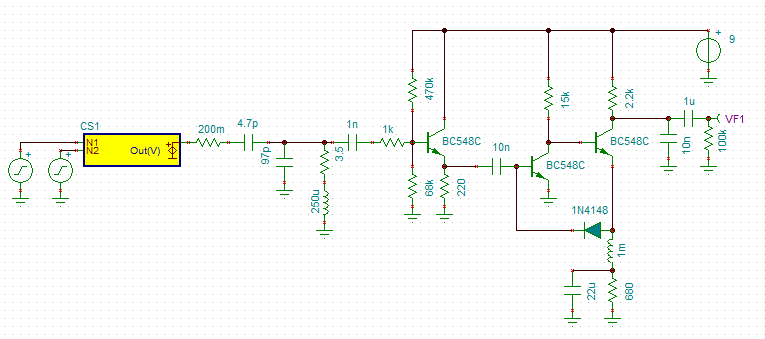
As the receiver noise is already high the best way to improve the receiver is with a pre-amp or an impedance matching buffer:
![]()
The buffer has a 15k input impedance so no impedance tap is required.
AlanX
-
Low Signal Stength
11/12/2016 at 22:52 • 0 commentsLow Signal Strength?
I assembled the two transistor reflex circuit:
![]()
I went with this design as I have built it before and it works.
I did model this circuit in the simulator and the Ge diode can be swapped with a silicon (the diode bias current is about 1.8 uA).
Also the audio output increases as a square of the signal strength (interesting?).
Well the performance was poor, I could just make out a local 720 kHz station.
- Had to ground the tuning coil to the circuit ground to stop audio oscillation.
- Plenty of hum from my soldering iron.
- Plenty of transistor noise.
- All the transistor voltages are correct.
- Not much better than a crystal set with a good antenna?
- Swapped my coil with a MW ferrite antenna coil and it was worse?
So I think the circuit is working properly, just low signal?
- Swapped out the Ge diode (1N34A) for a 1N4148 and the performance is about the same (maybe better).
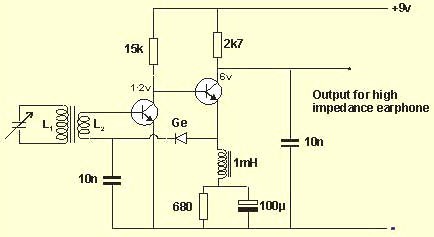
Here is the reflex:
![]()
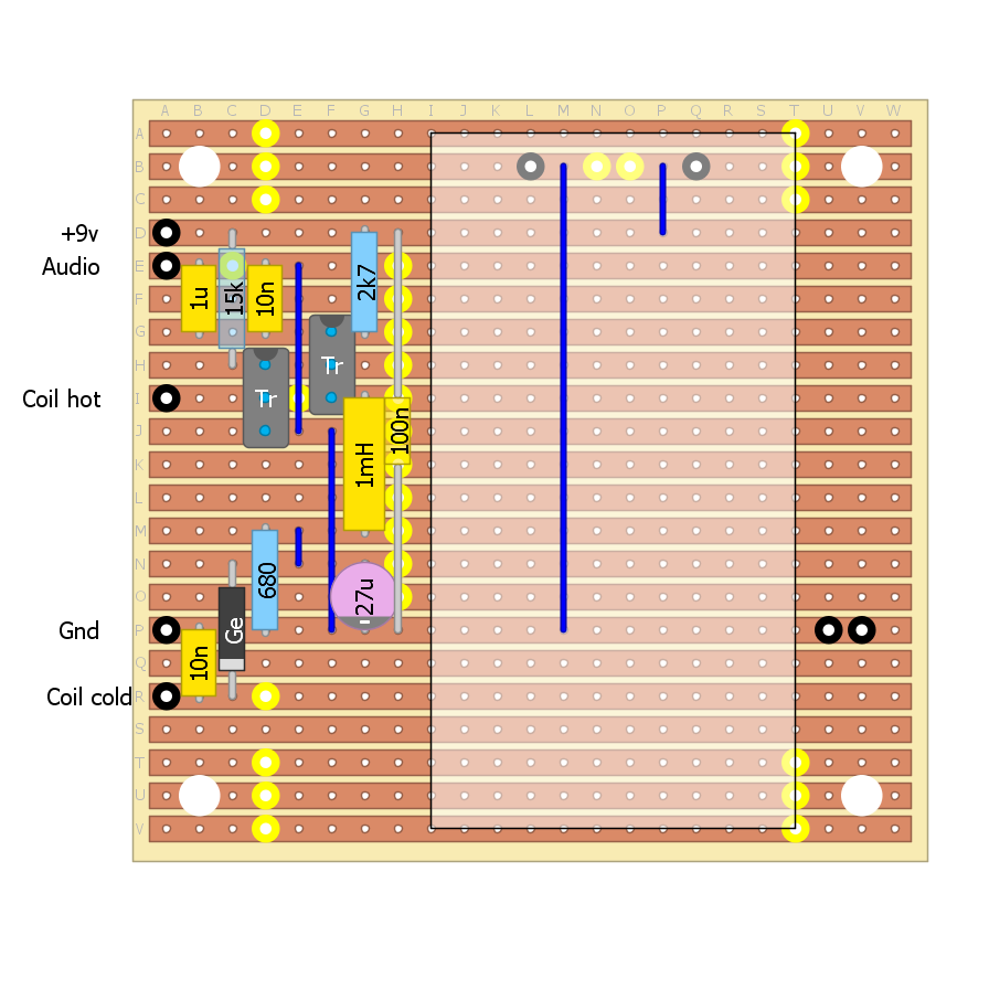
And here is the DIYLC design:
![]()
Th only change was to reduce the 100 uF emitter by pass to to 27 uF (25 uF would have been better) to centre the audio gain at 1 kHz.
AlanX
-
MW/AM Radio Receiver
11/12/2016 at 22:48 • 0 commentsReviving a Dead MW/AM Reflex Project
Long long ago
Long long ago I built a valve MW reflex receiver.
I could not get it to work so it went into the shed.
I can't remember how many years it has been in the shed.
Anyway with my revisit of MW receivers I pulled it out as a base for further experiments.
First I check the batteries and they were dead an I could not revive them.
Not a good idea to use sealed lead batteries in this type of project!
Next I saw that fake 15 mH choke (that is really a 15 uH choke).
Now the 15 mH choke was light on for this radio so 15 uH was the reason it did not work.
I had the ground and antenna hooked up the wrong way as well.
Anyway, no batteries so I pull it apart to try it out as a crystal set.
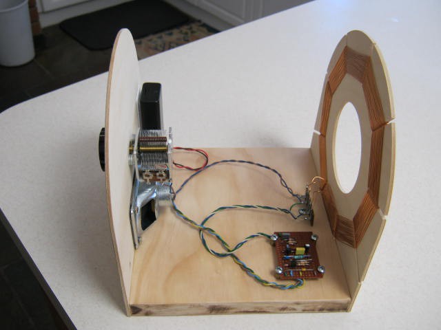
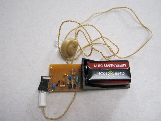
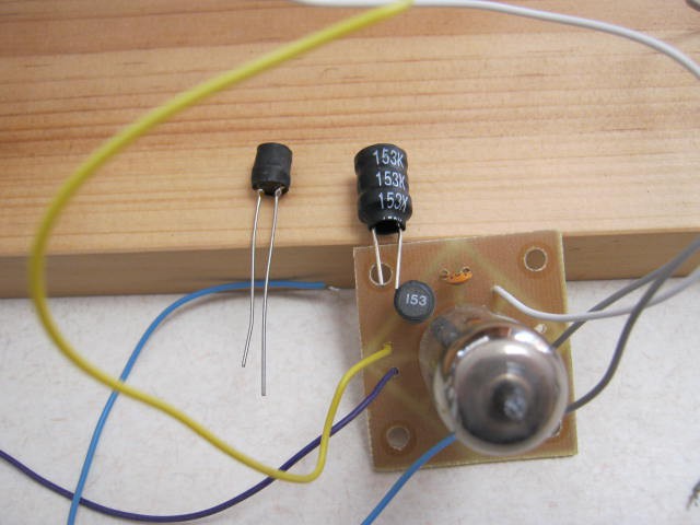
Here is the set in pieces:
![]()
And here is the fake 15mH next to a real one:
![]()
You can see that circuit board was made using a hacksaw to cut the copper foil!
Crystal Set
Anyway, I put up a 15 m long-wire aerial and a ground, added a Ge diode and listened for any MW stations using a crystal ear-piece.
Pretty poor. I could just detect a station on 720 kHz at the top end of the tuning range.
As the coil has not taps and the diode was across top of the coil the selectivity was dreadful.
So what was wrong?
First the coil is far from optimal with too much self-capacitance. The L/D is about 1.5 while the optimal L/D is about 0.5.
Second, the wire spacing should be about 1 to 1 not close wound as I have done.
Third, the black coil former is likely black as it has graphite in it, not good for Q.
And lastly no impedance taps for the diode.
So that coil will have to go.
Transistor Reflex
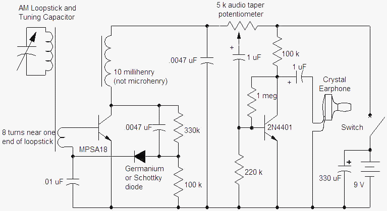
As a base for further experiments there is an old design I have used (long long ago) that works very well:
![]()
But I have gone with this one but less the audio amp:
![]()
(source: http://www.techlib.com/electronics/reflex.htm)
The Ic is about 1.1 mA and the diode bias about 3 uA.
This author has a preference for aerial loops which I rather like.
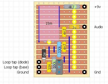
Here is the strip-board layout:
![]()
The new coil
After a bit of research I elected to build a spider coil.
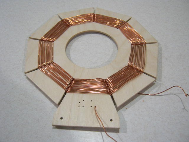
I had 14 m of 1 mm diameter enamel coated copper wire (which I thought would be enough - wrong!).
I designed for 250 uH, here is the web after I ran out of wire (24 turns out of 37 turns):
![]()
Two mistakes:
- 1 mm wire is a bit hard to handle, and
- the hole in the middle is just a fraction too small to put my hand through easily.
I will finish this design but the next one will use 0.8 mm wire.
The diameter of the coil frame is 200 mm (8 inches).
The design has 34 antenna turns and 3 coupling turns.
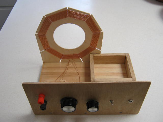
The new new coil
Too hard to get enough 1 mm diameter wire so I dropped down to 0.8 mm diameter wire and redesigned the coil.
Here is the finished coil:
![]()
And another view:
![]()
This coil is 32 turns total, 29 for the antenna coil and 3 for the coupling coil.
I was designed for a reflex set up.
I am staring to think the ratio 10:1 may be a bit extreme.
This was based on the design from http://www.techlib.com/electronics/reflex.htm.
It had 20 turns and 2 turns.
The problem with 10:1 is it is not much good for a crystal set.
Something like 2:1 or 3:1 would be better for a crystal set.
I can rewind the coupling coil to increase the turns later if needed.
As a crystal set this coil is just as bad as the first one due to over-loading by the diode and ear-piece.
It does not seem that reception of MW signals is not that great where I am located.
AlanX