It took me quite a while to build a working wire drive that can provide constant speed, (almost) constant tension and a small footprint, but I think this design can be used for further construction.
The new wire is placed on the front spool which is braked by a Nema 23 stepper with shorted windings. The braking and with it the tension increases with the wire speed and should be otherwise quite constant.
If needed I could also replace it with a mechanical brake, but using the shorted motor is likely the most simple solution.
From the spool the wire is guided over a load cell which measures the tension before the wire drive for showing its value in gramms on a 7 segment display.
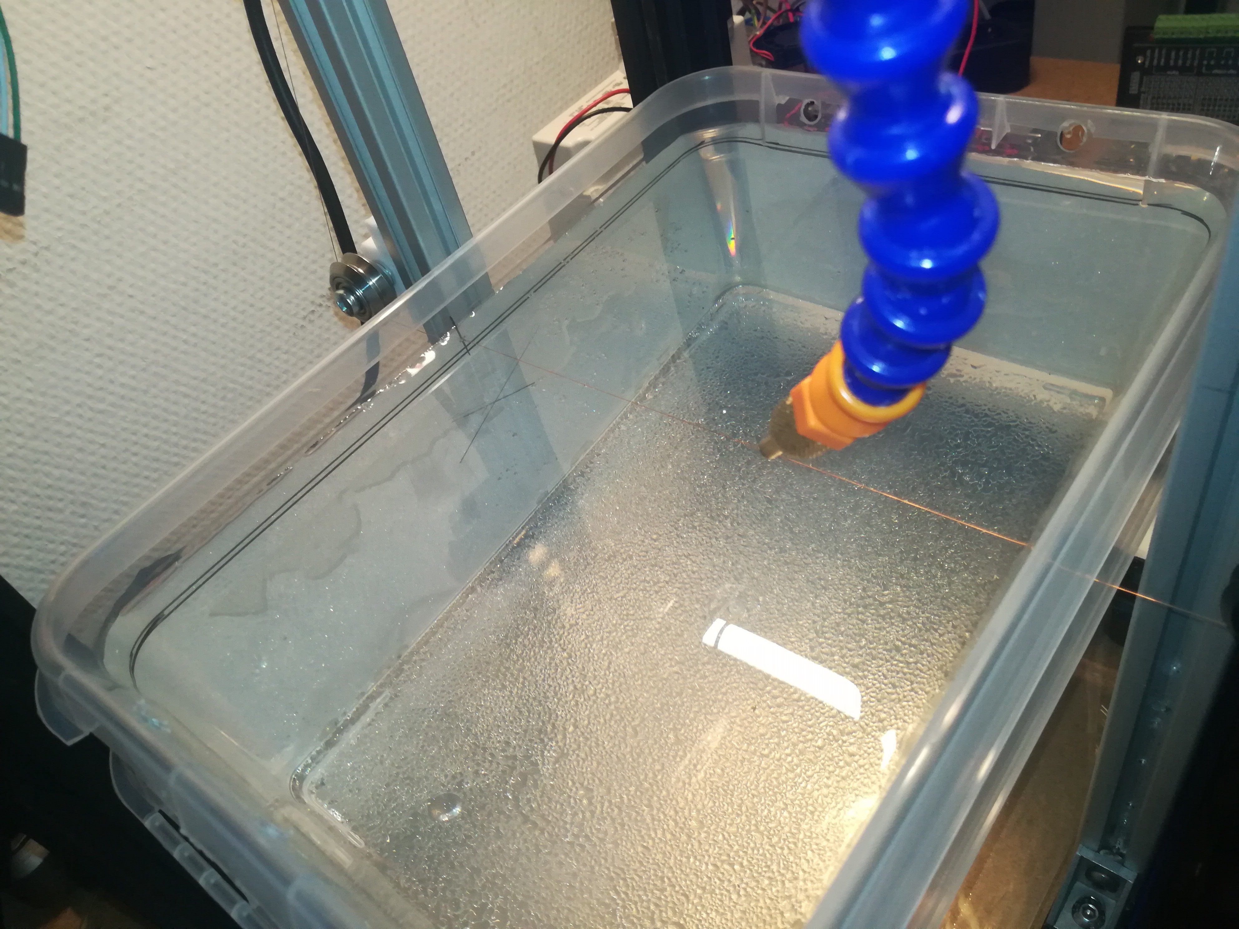
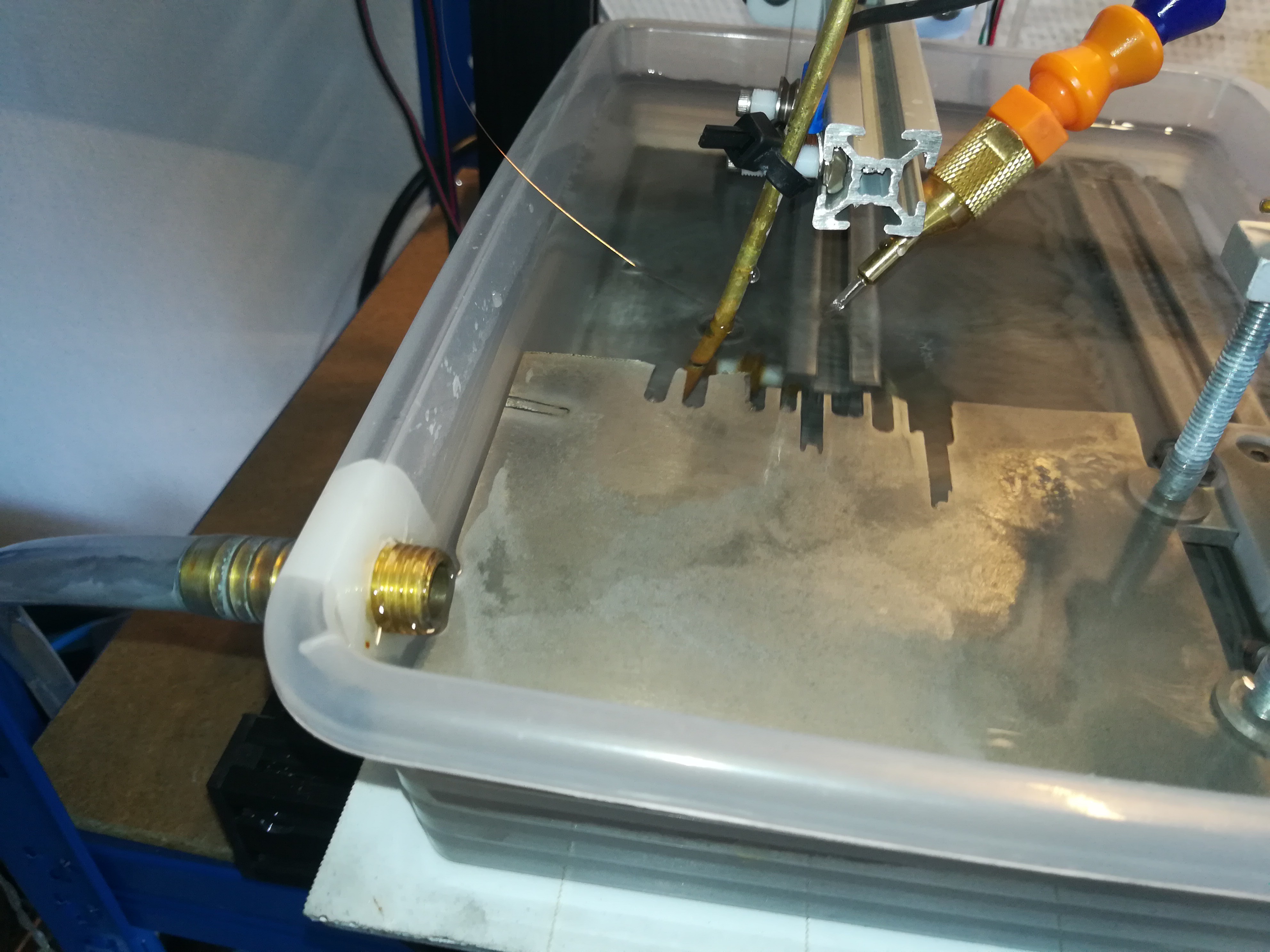
From there it is guided through the water bath (not shown in the video) and to a stainless steel roll which is connected to the EDM circuit.
From there it is guided to the wire drive which is made of two shafts with three V rollers placed on each which are both driven with a GT2 belt on the backside. The wire is wound about four turns onto it to increase the contact surface and prevent it from slipping. The wire drive pulls the wire from the new wire spool with a Nema 23 and determines the wire speed.
From there the wire is guided over another load cell that measures the tension after the wire drive to show it on a 7 segment display and also to detect when the tension has lowered to a setpoint where the old wire spool's Nema 23 stepper has to wind up the old wire to complete the wire drive.
Next up is building a X and Z axis to move the workpiece against the wire.
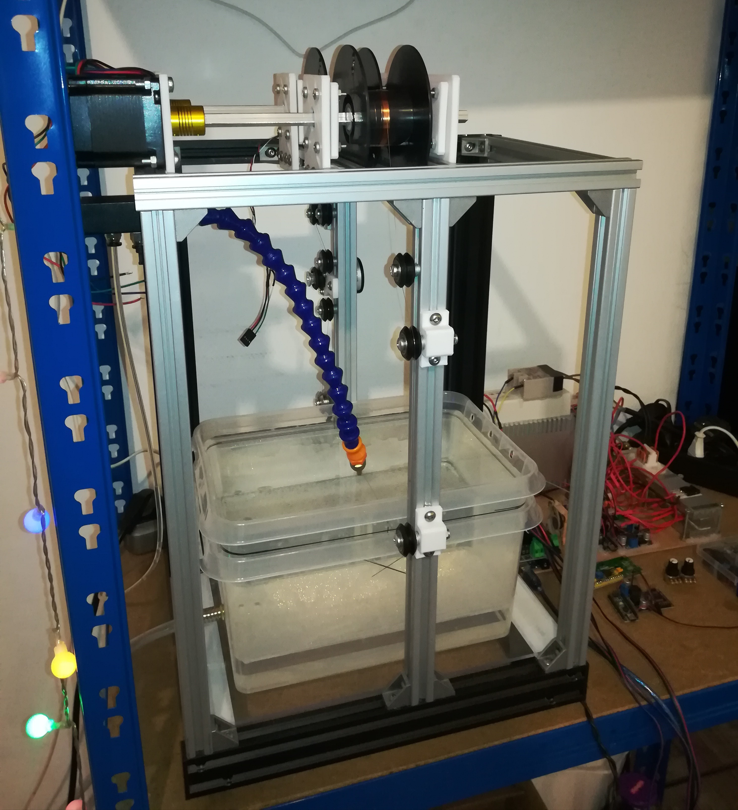
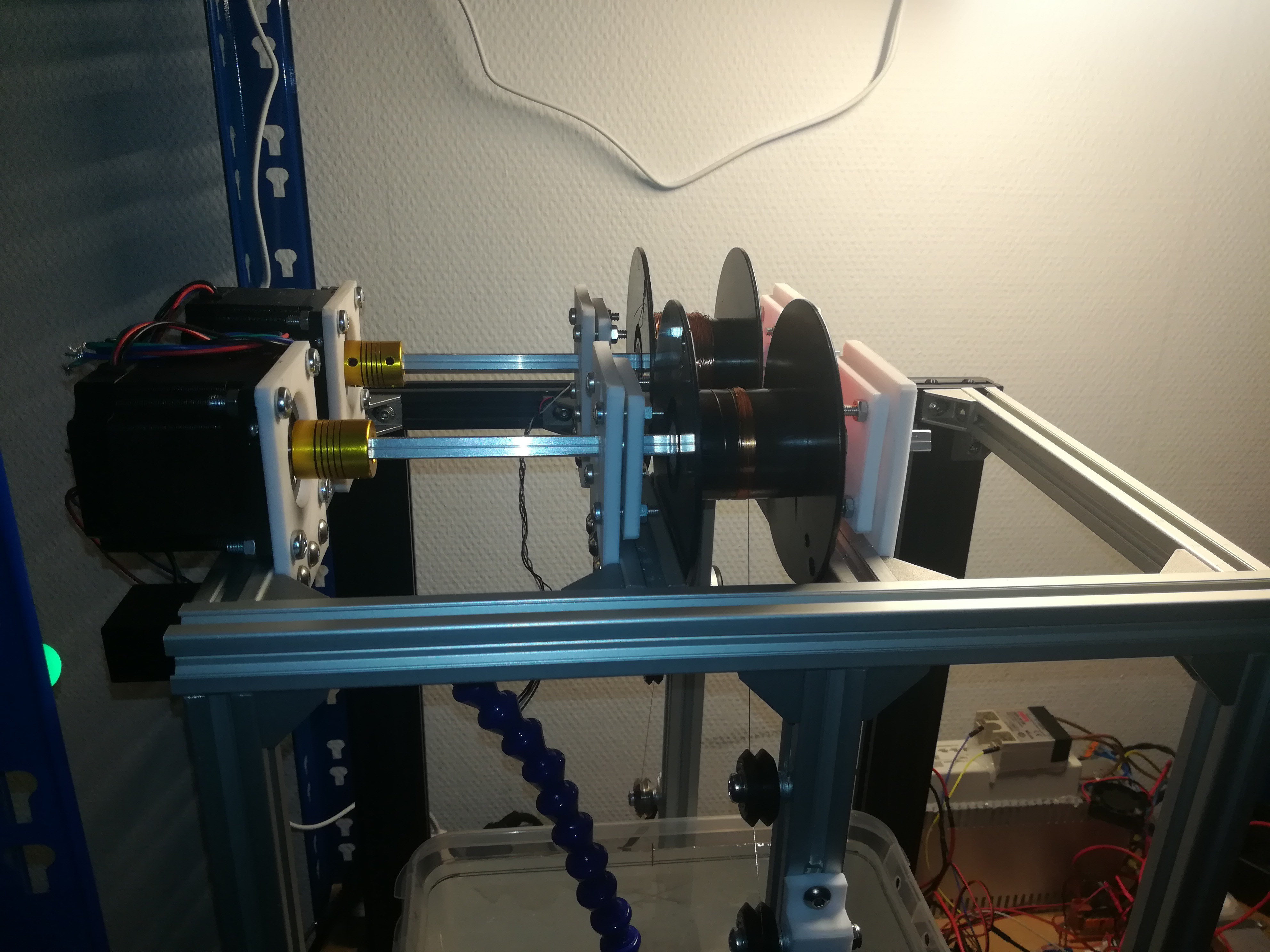
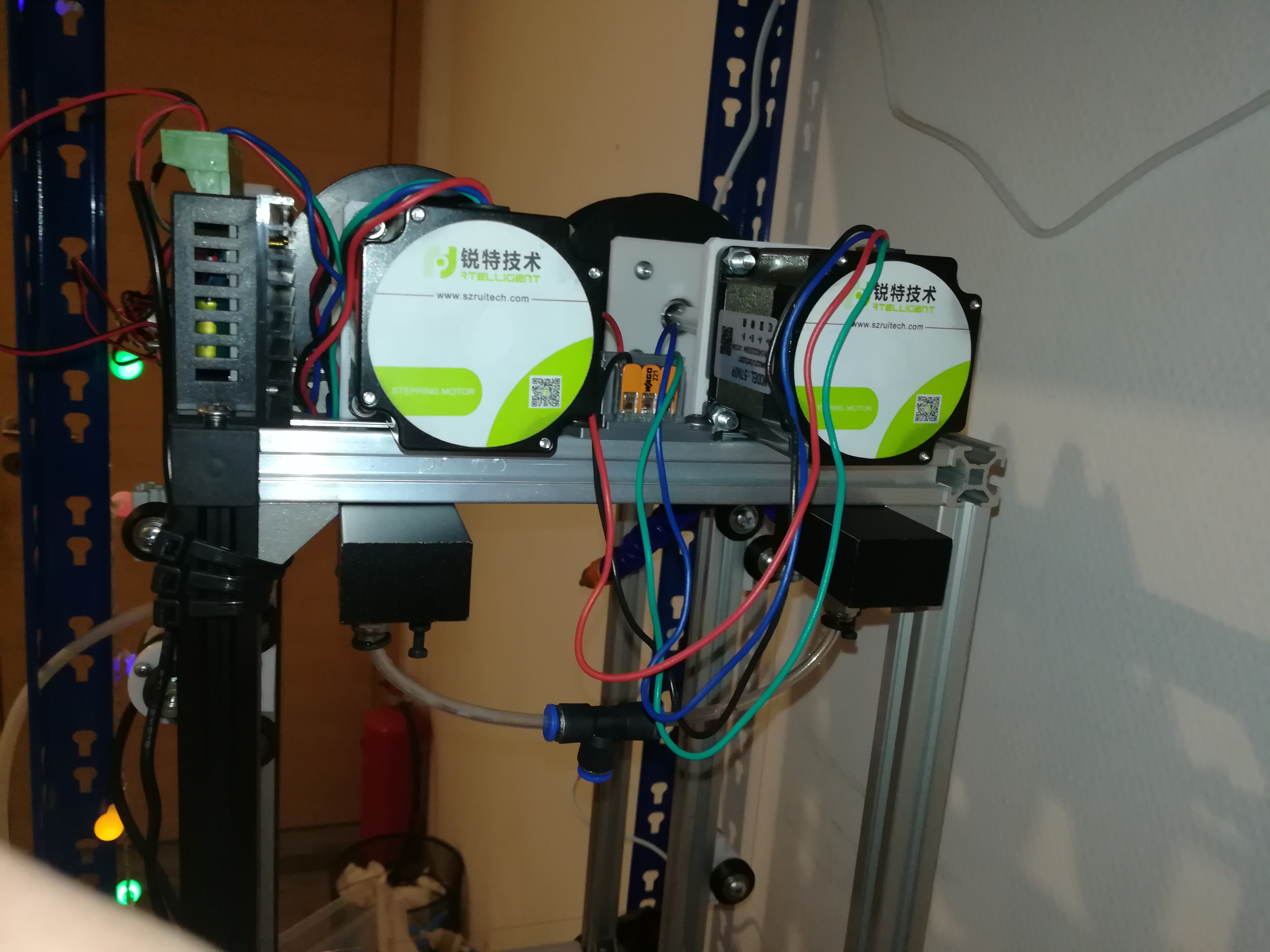
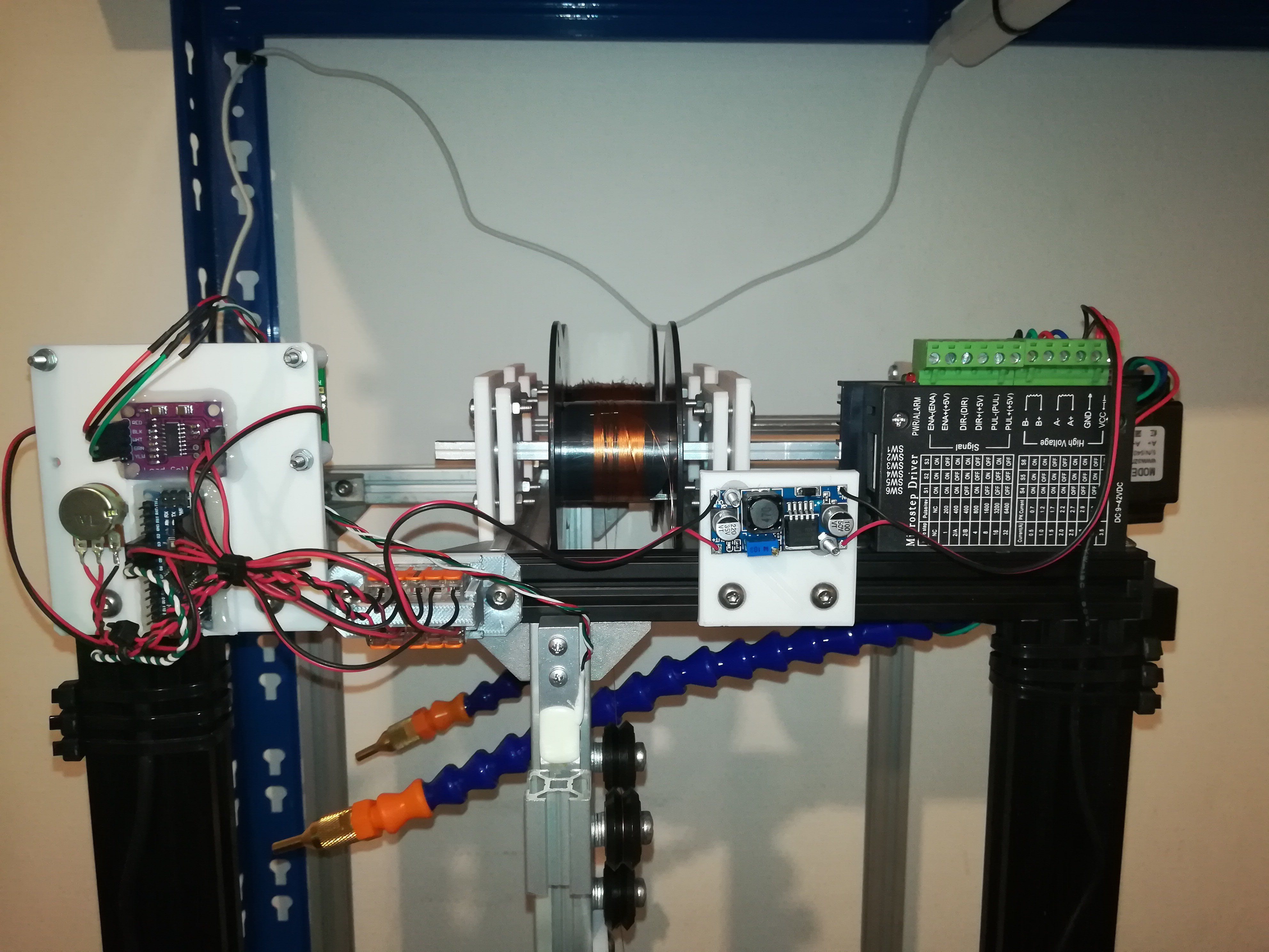
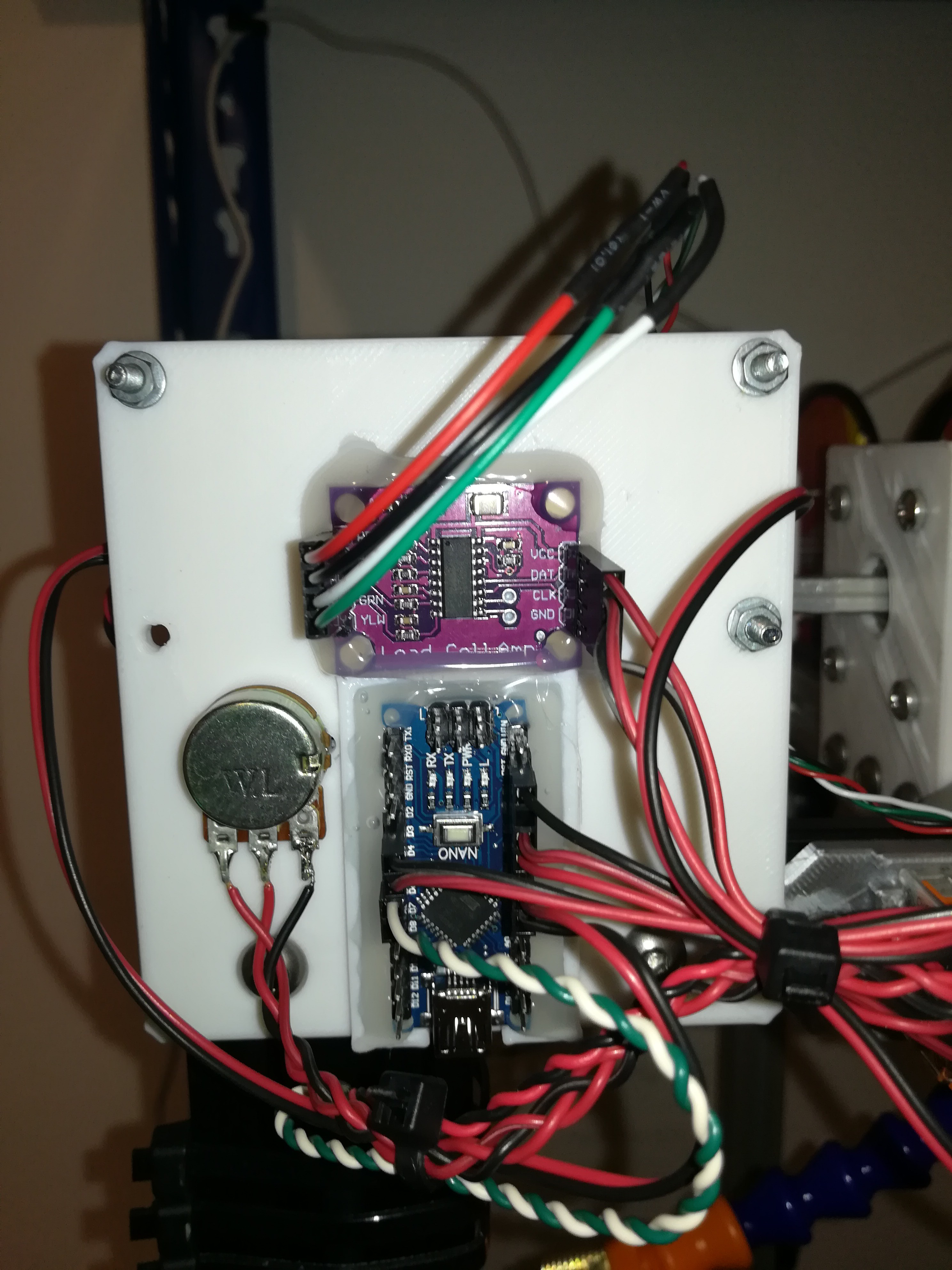
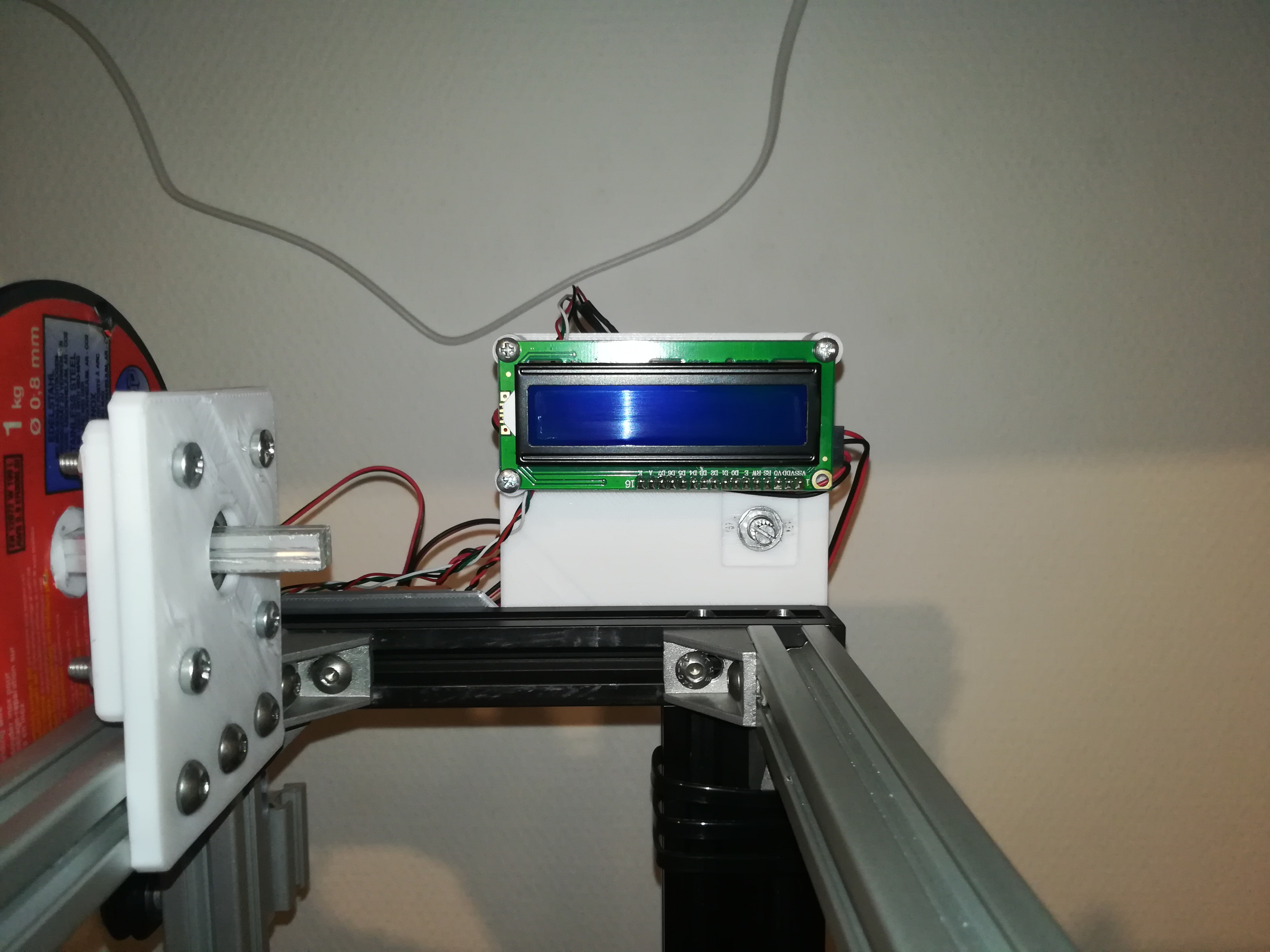
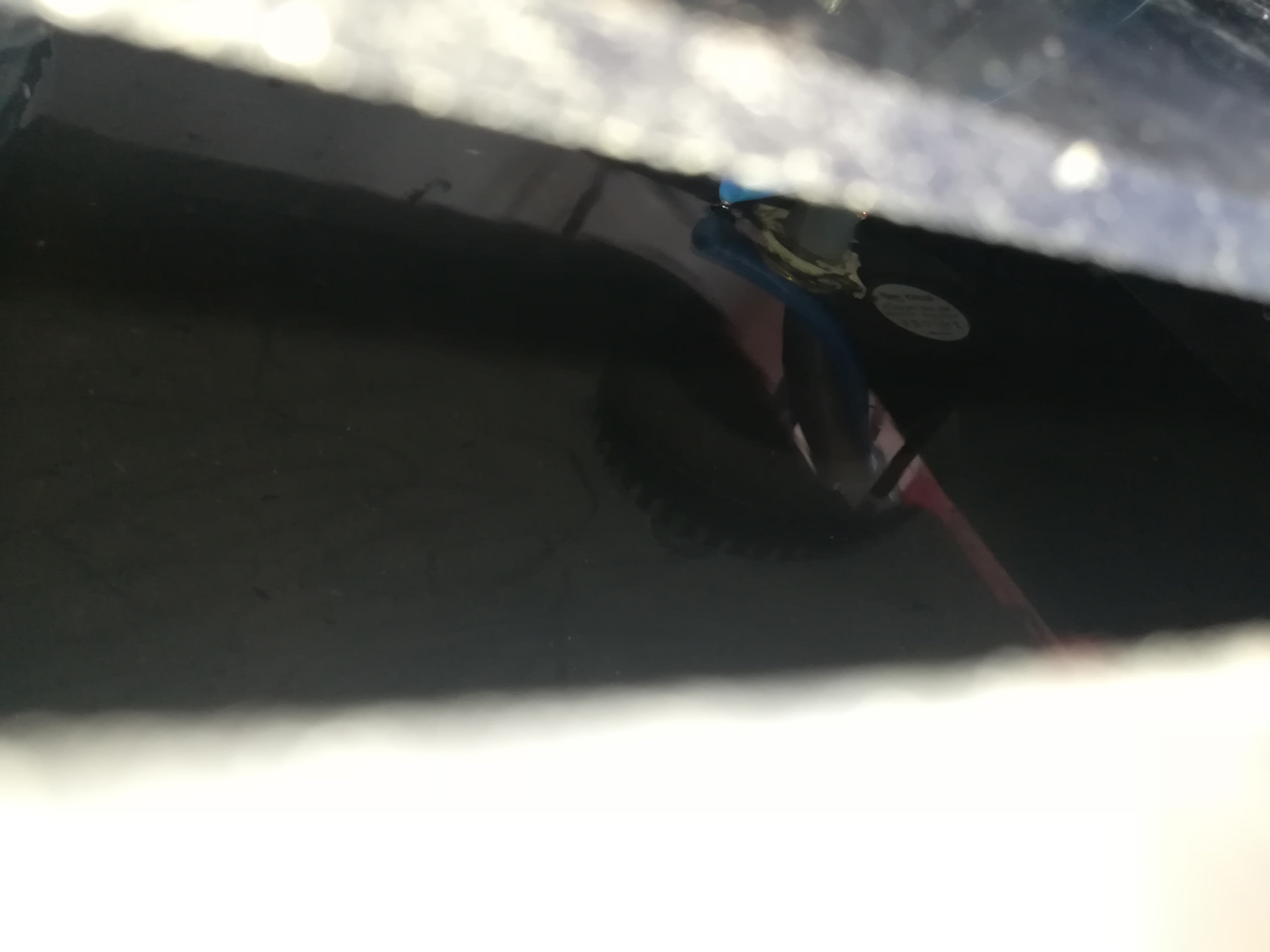
Here are some pictures of my latest progress, where you can see the spools, load cell, encoder and guide rollers.
I used two welding wire spools and grooved 625ZZ (Ender 3 Rollers) for guiding the wire, Nema 23 motors for driving the wire and mounted it in a horizontal setup, so that the wire can stay on its position while the workpiece can be moved along the X and Z axis. I thought this could maybe made the machine easier to build, because you only have to add some rollers and parts to the frame to build the wire guide.
Now I'm working on the electronics for driving the wire, so that I can do a test run as soon as possible.
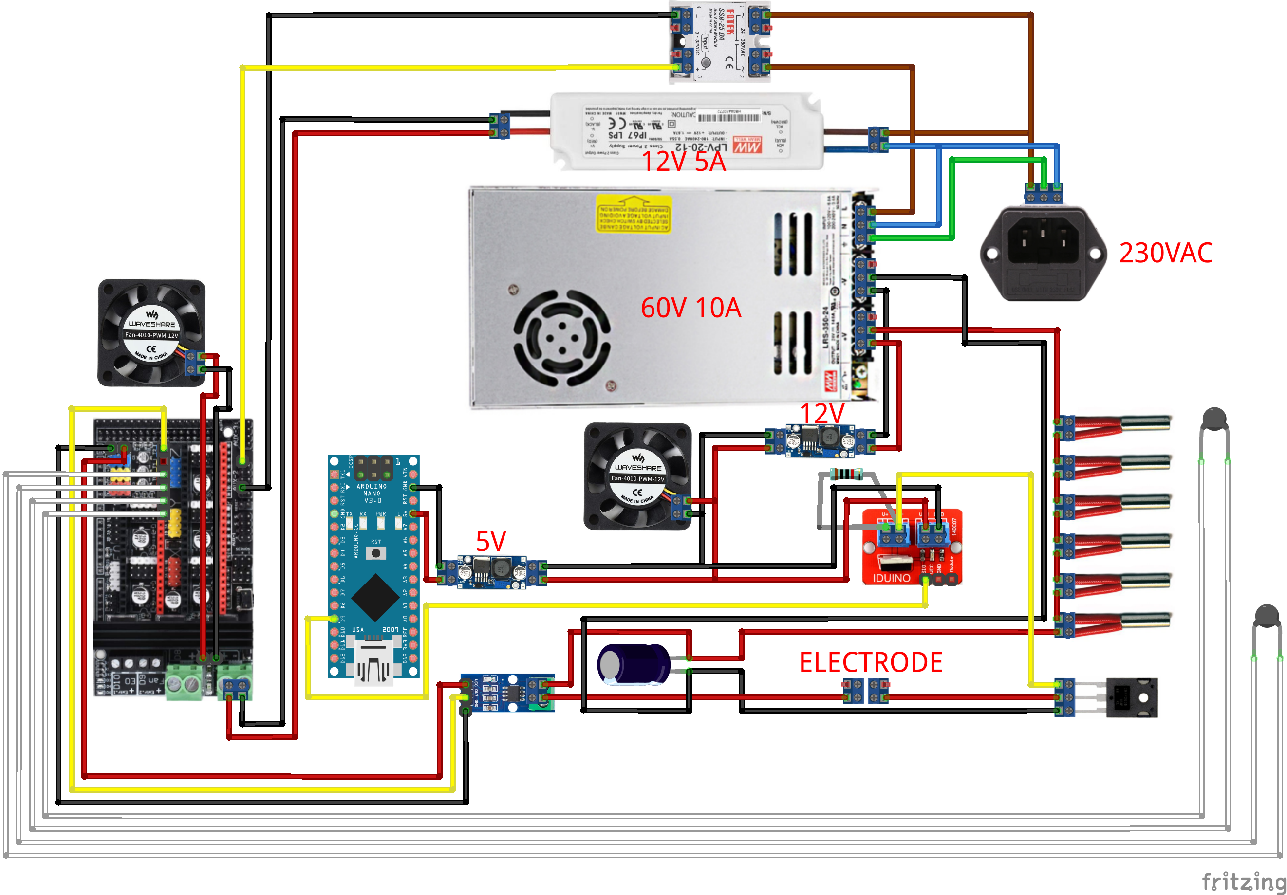
I added and connected some electronic parts. This is one possible solution for driving the wire. I shorted both windings of one stepper motor to provide some resistance for tightening the wire and connected the other stepper motor to a driver for pulling the wire and also connected an encoder, load cell, I2C LCD and potentiometer to an Arduino NANO. The encoder is used for measuring wire speed and the load cell is used for measuring the tension of the wire. If the wire would get wrapped around the spool at constant speed, the outer diameter would increase and with it the wire speed. Instead of that I want to measure the wire speed with an encoder and adjust the speed of the stepper motor to keep the wire speed constant. For now I only want to use the measured tension for monitoring and testing. Later, both values, wire speed and tension should be displayed on the LCD and the potentiometer should be used for adjusting wire speed.
With everything wired up it's time to write some Arduino code to get ready for testing.
In the last days, I thought a lot about how I could design the wire guide. I've seen the videos from BAXEDM, ActionBox and others on youtube and it seems like their designs are doing a great job at guiding the wire and so I will try to build something similar, but more compact and as simple as possible.
My idea for the design, that I'm planning to build in the next few days, is to simplify the wire guide a bit by keeping it similar to a tape recorder or an old tape drive computer.
My current plan is to keep the wire guide stationary while moving the workpiece.
I thought about removing the Y axis from the 3D printer and using the Z axis as new Y axis. This way the X axis and former Z axis would form an upreight X and Y axis.
After that I would add another motor to the new Y axis and clamps for workpieces to the X axis which can then be moved left/right and up/down. I will likely not cut workpieces weighing more than 5kg on this machine, so I think that the weight should not be a problem.
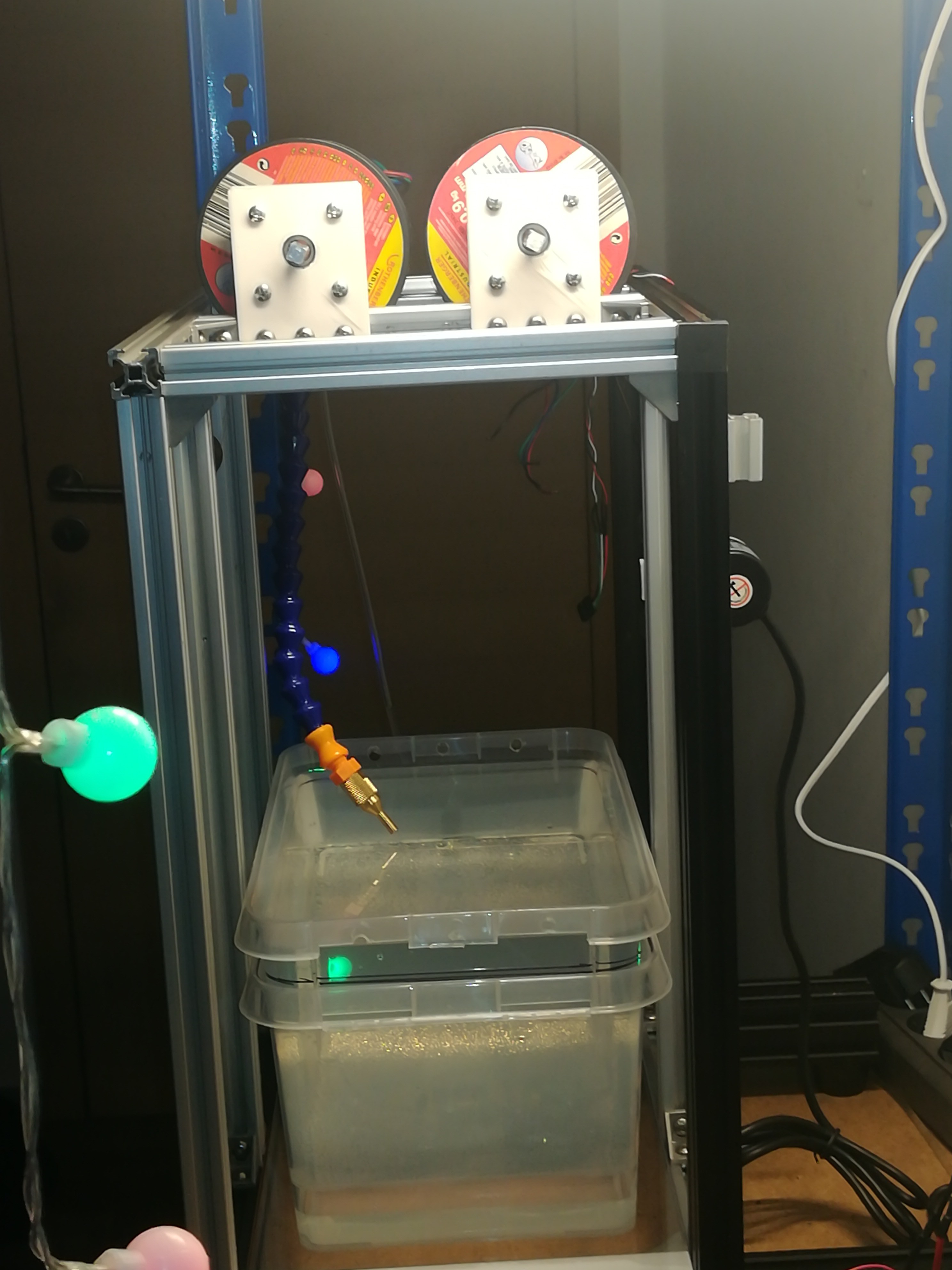
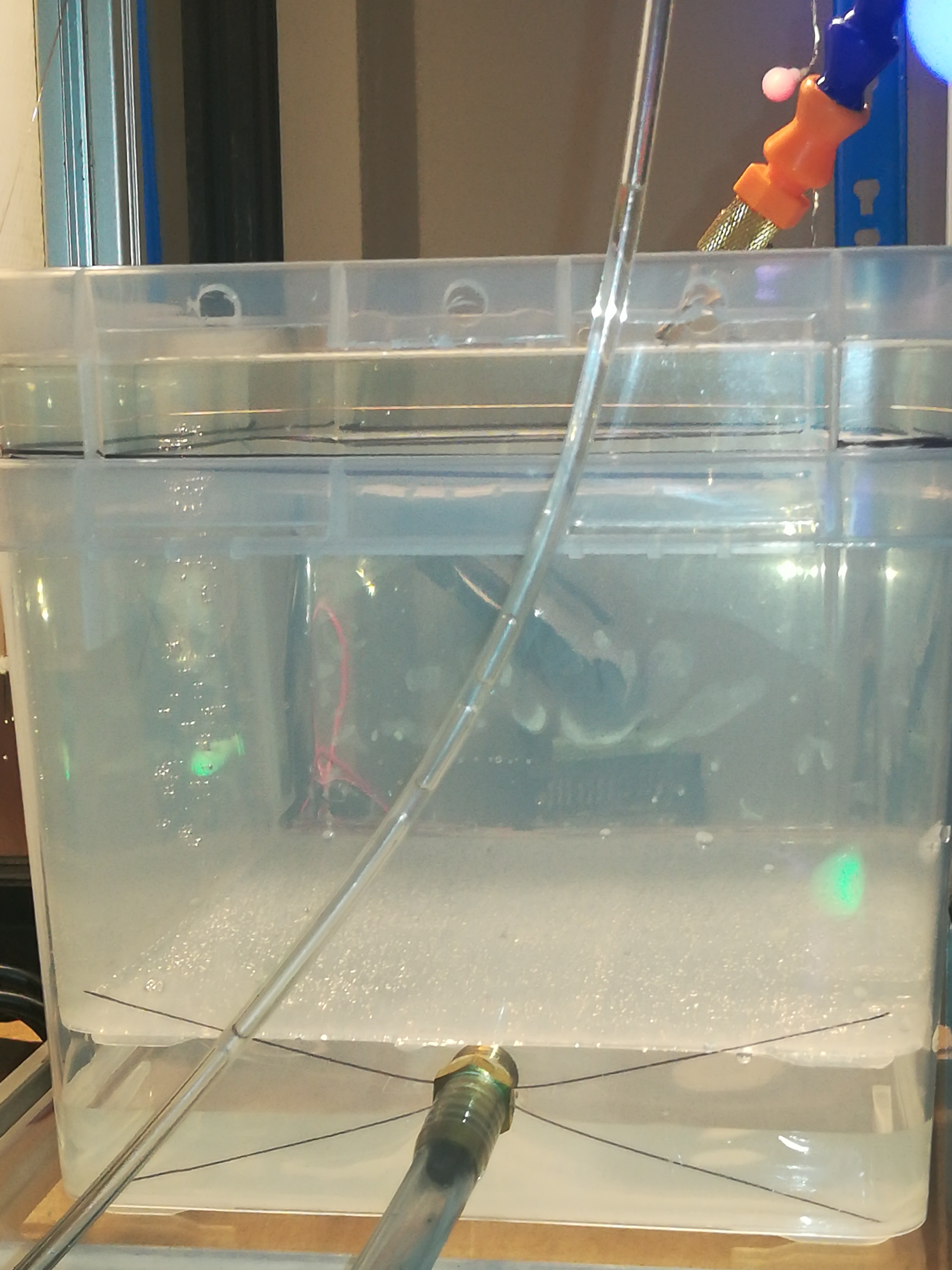
Instead of the old Y axis, I would place a water container with tiny holes for the wire in its sidewalls, at its position. The container would be filled with water and a bit of the water would leak out at the inlet for the wire and so I would place another container under it to collect the water, so that it can flow back to the water system.
The roll with the new wire and the roll for the old wire would be mounted on top of the printer. (Maybe I would add some additional bracing to get more surface for mounting the rolls on top of it.) The wire would then be guided from the new wire spool down to a bearing, to a bearing with a load cell, to another bearing, through the water container, to a bearing, to an encoder wheel, to another bearing and back to the used wire spool.
At the moment this is just an idea and I hope that I can make the build a bit simpler by keeping the wire guide stationary and moving the workpiece instead of it.
It could also turn out, that its more complicated or not possible to do it this way, so that I have do build it the other way around, but at the end I'm doing these projects just for fun and so it will not be a big deal to cancel an idea and try out a new one.
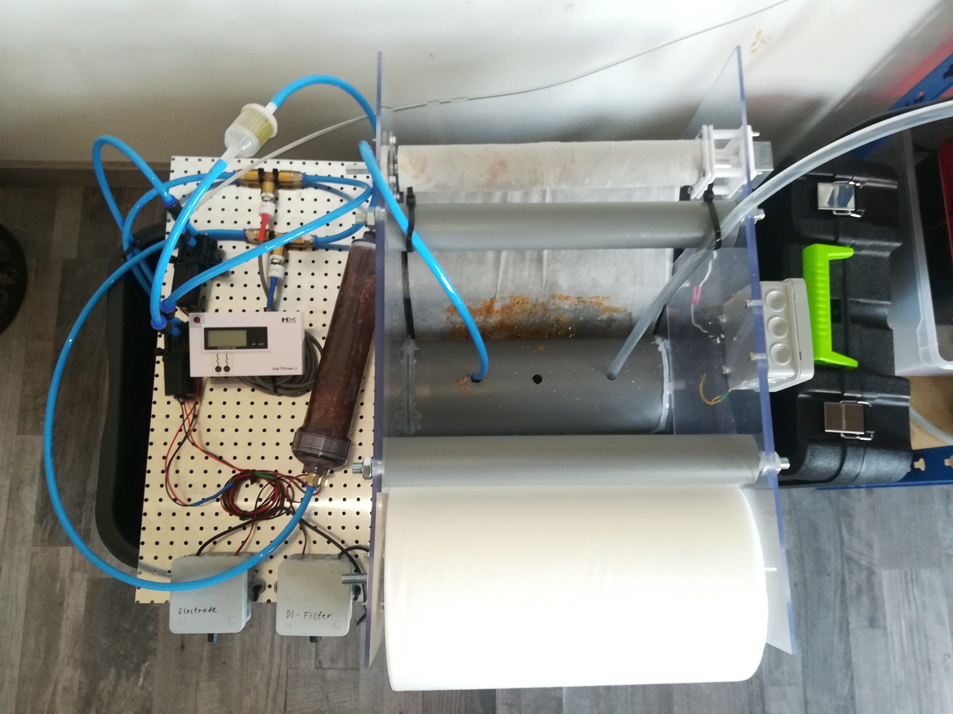
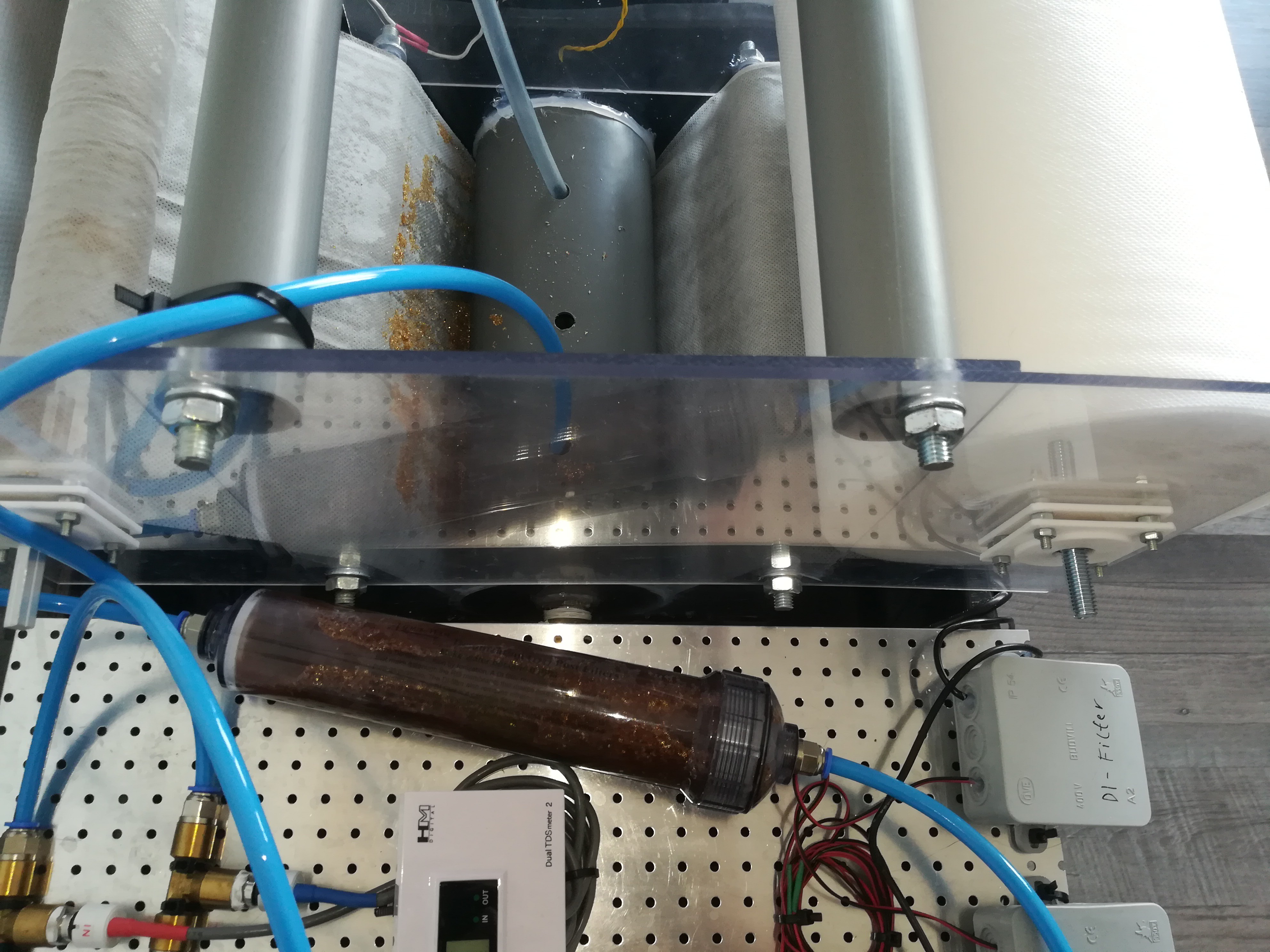
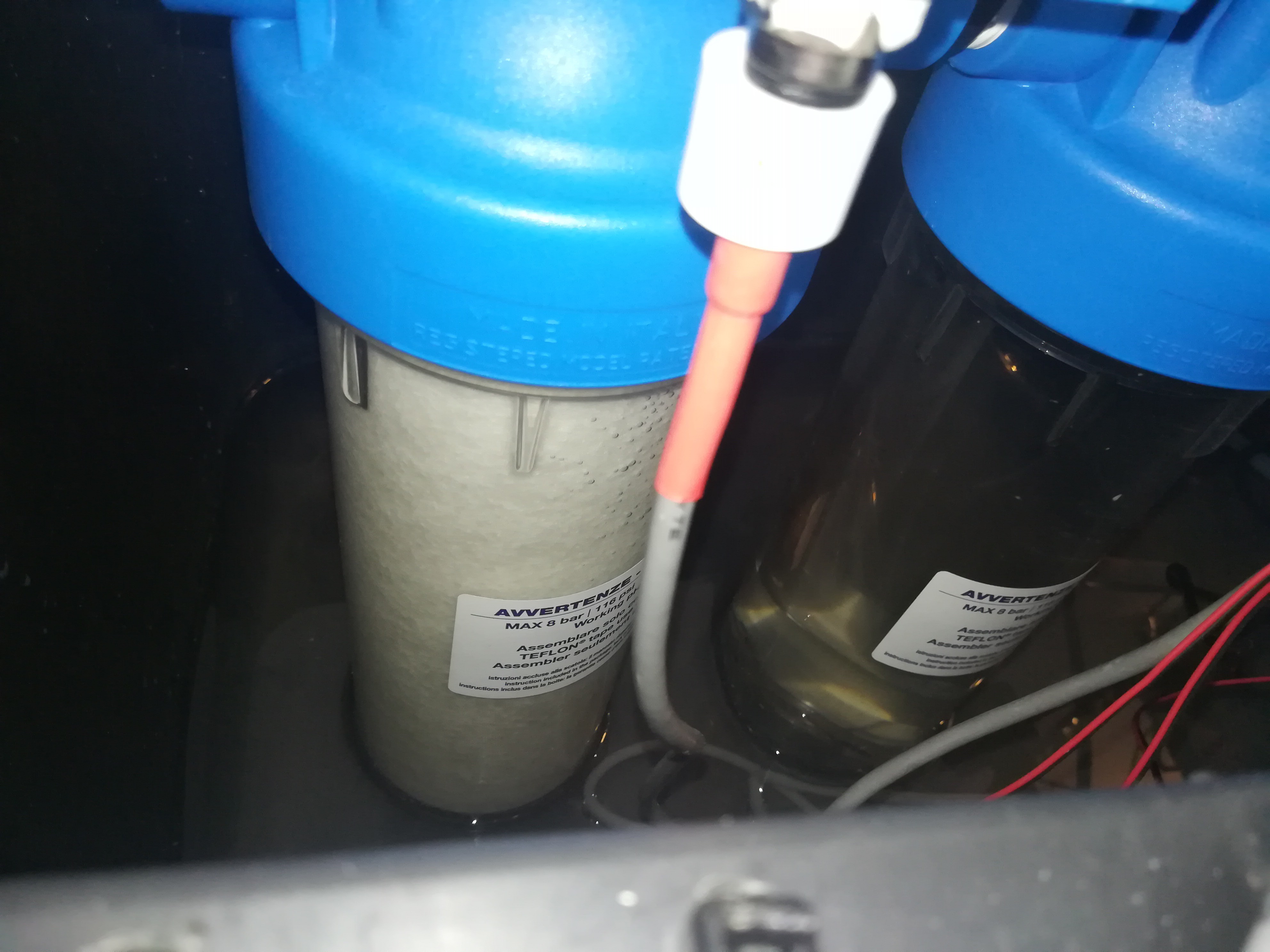
While cutting, the old filter setup got clogged just after a short time, so I replaced the paper filter and filter cartridges with a fleece filter.
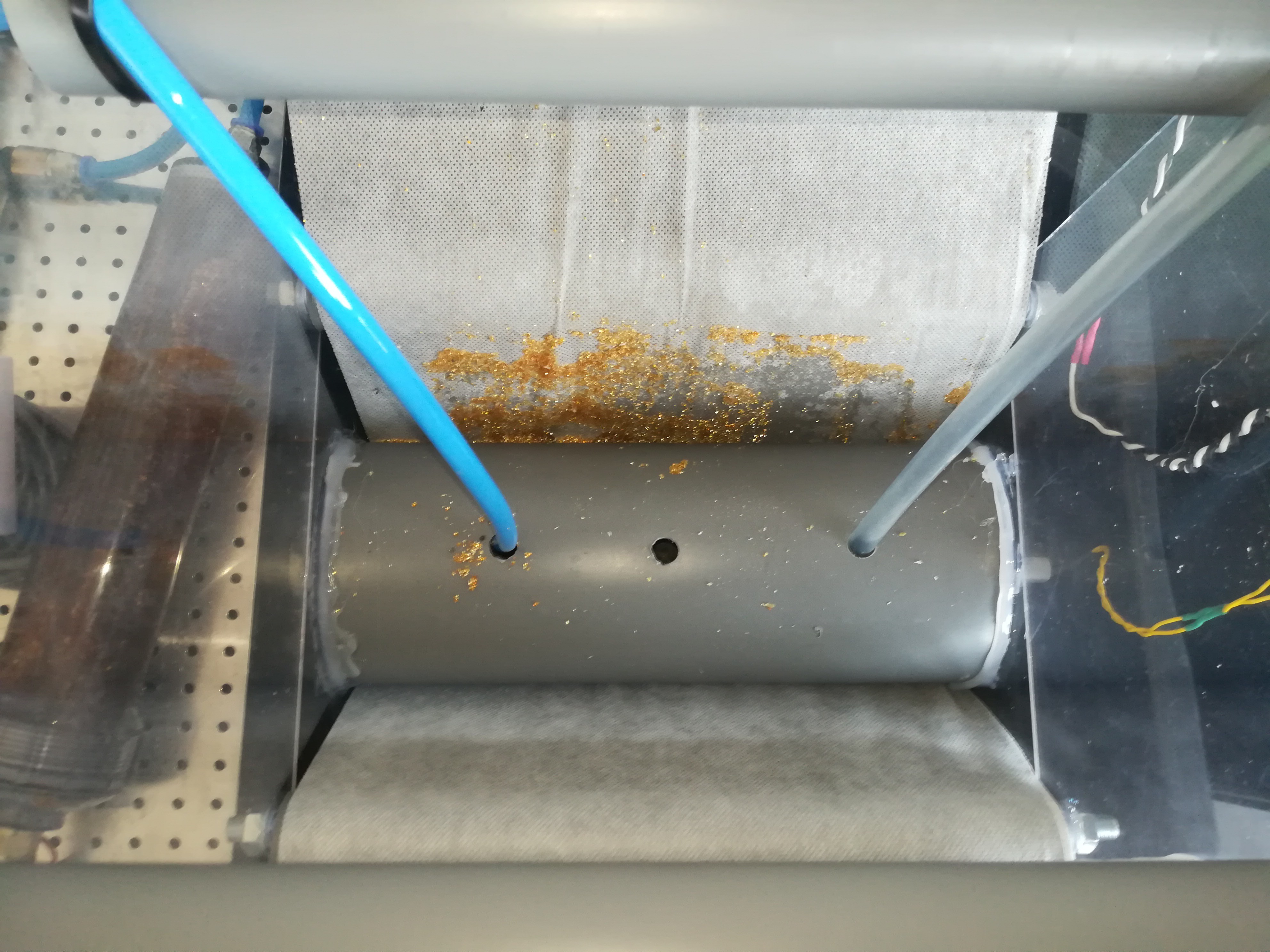
The filter works in the way, that the water from the fish tank pump, from the DI filter and from the EDM machine flows to the 110mm tube in the middle of the filter. This tube is 300mm long and has a perforated 200x50mm surface at the bottom of it.
New fleece is guided from the new fleece roll along the bottom of the tube to the used fleece roll. The perforated surface is 100mm shorter than the tube and the fleece to give the fleece enough surface to seal against the tube left and right from the perforated surface, so that the water can not bypass the fleece.
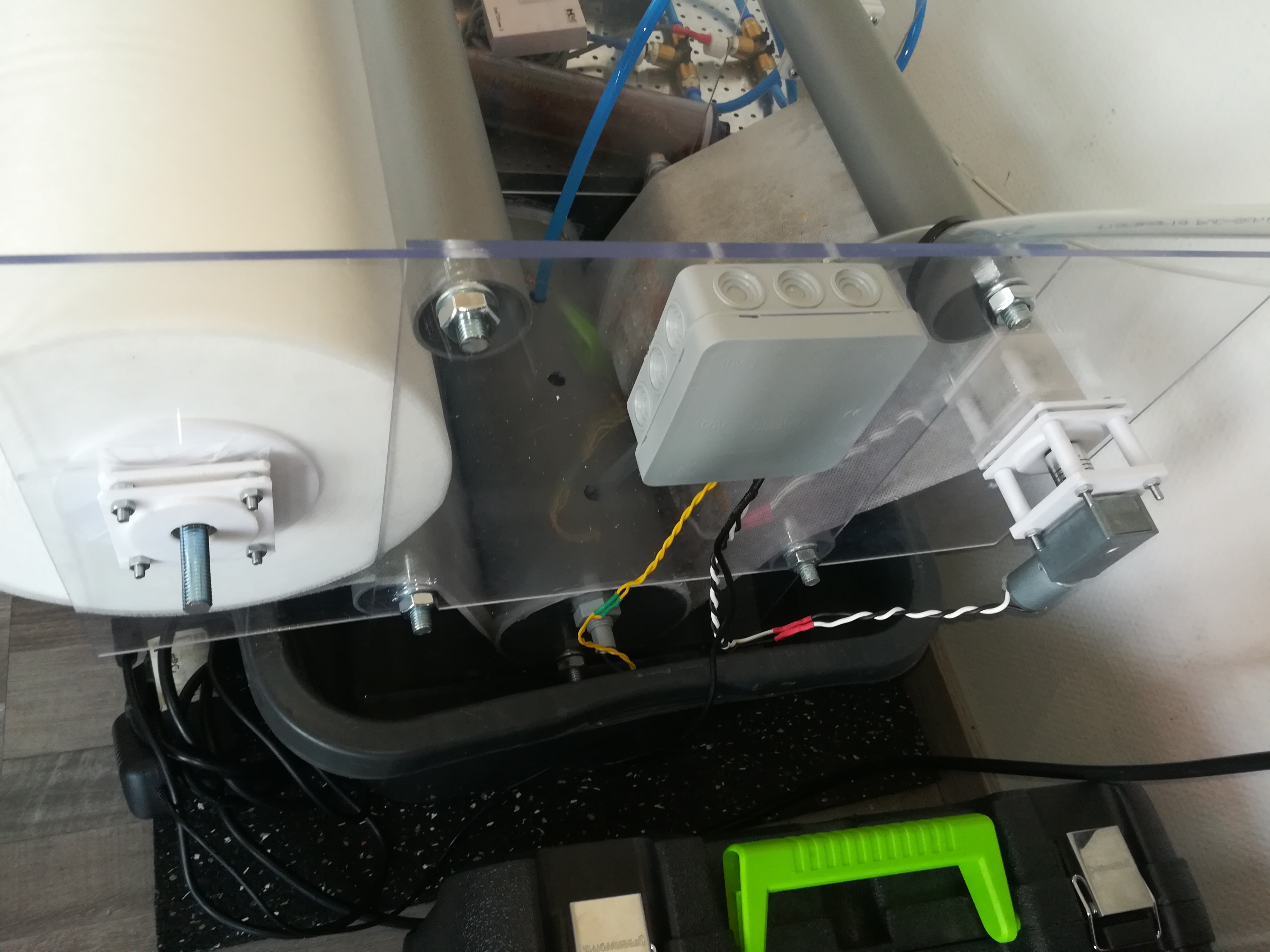
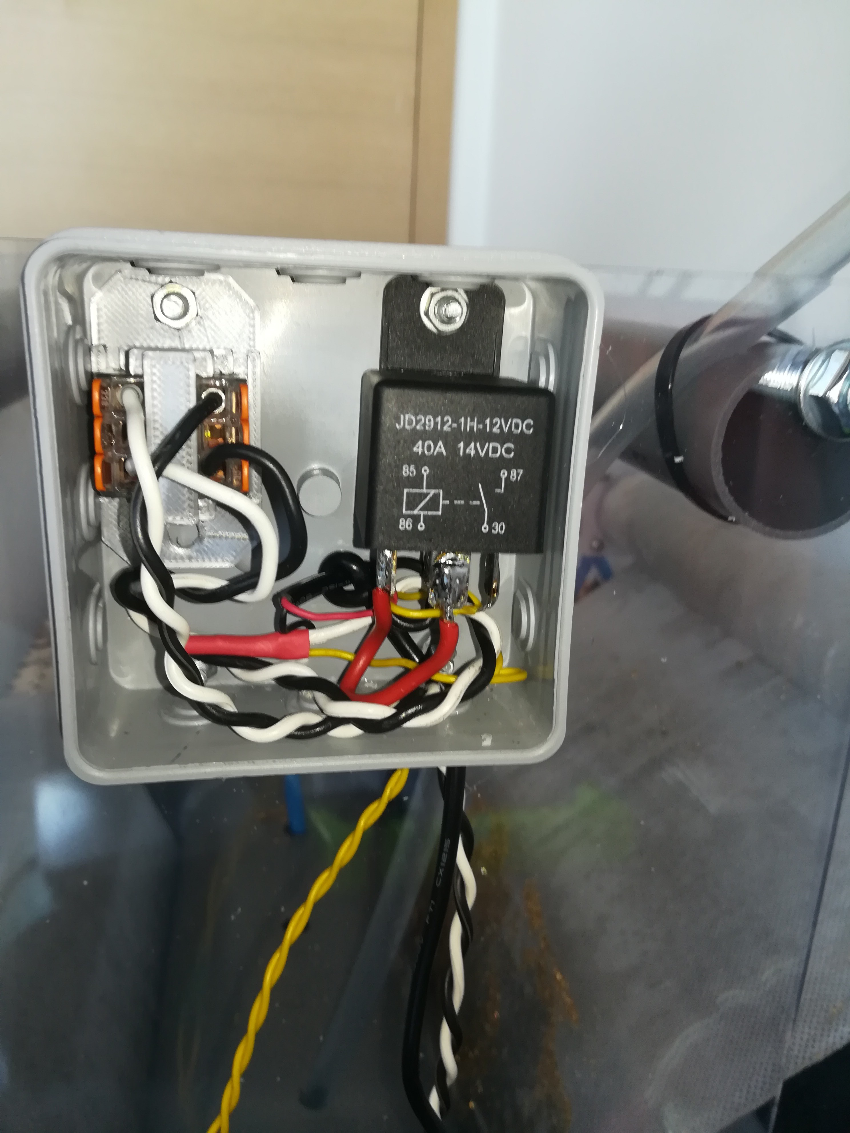
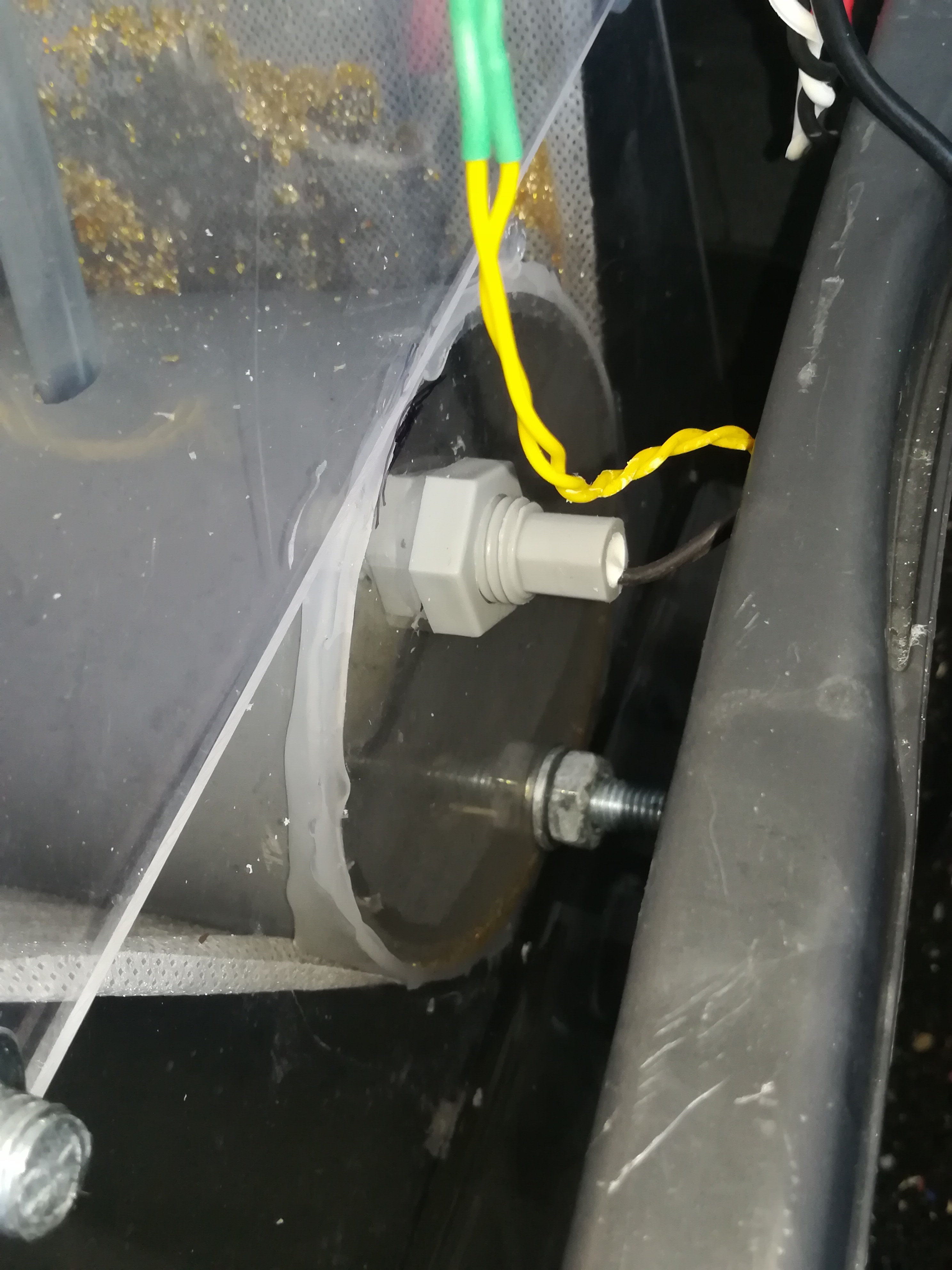
When the fleece gets clogged, the water rises in the tube until a float switch turns on a motor, that motor pulls new fleece from the roll until the water level is low enough to turn off the motor again.
I tested the operation of the filter with granules from a DI filter and also while cutting some stuff, so it seems that the filter works better than the old filter setup.
Even though the filter has larger pores, it is able to keep the water clean / transparent all the time.
I also changed the tubing.
The pump for the DI filter and the pump that pumps the water to the electrode now have separate inlets.
So, with the new filter setup the system should be ready for longer testing operations.
To get a continuous arc the electrode or wire has to keep the right distance to the workpiece at any time. For keeping the arc at the right distance I wrote some code for the Marlin Firmware that measures a voltage provided by a current sensor to move the electrode towards the target position as long as the current is lower than a defined value. If the electrode touches the workpiece the current increases above the defined value and the electrode stops and moves back to where it came from until the current is again below the defined value. This gets repeated continuously until the electrode reaches the target. The electrode does that very fast at a low feedrate, so that it does not move a large distance in every direction and so it keeps the right distance at any time what leads to a stable arc.
If you are good at coding and want to integrate this feature into the Marlin Firmware, it would be nice if you could help me to clean up the code, to make that possible:
I think with the infos about the water system, electronics and the closed loop control you should be able to build your own sinker or drill EDM machine.
Because I want to use EDM as a more silent and more precise alternative to plasma cutting and CNC milling, I need to upgrade the machine so that it is able to cut out workpieces. The current problem with that is the wear of the electrode and so I need continuous refreshing of it, for what I will need a wire EDM system.
There are some good Wire EDM designs out there and I will try to build something like that by myself in the next days and weeks.
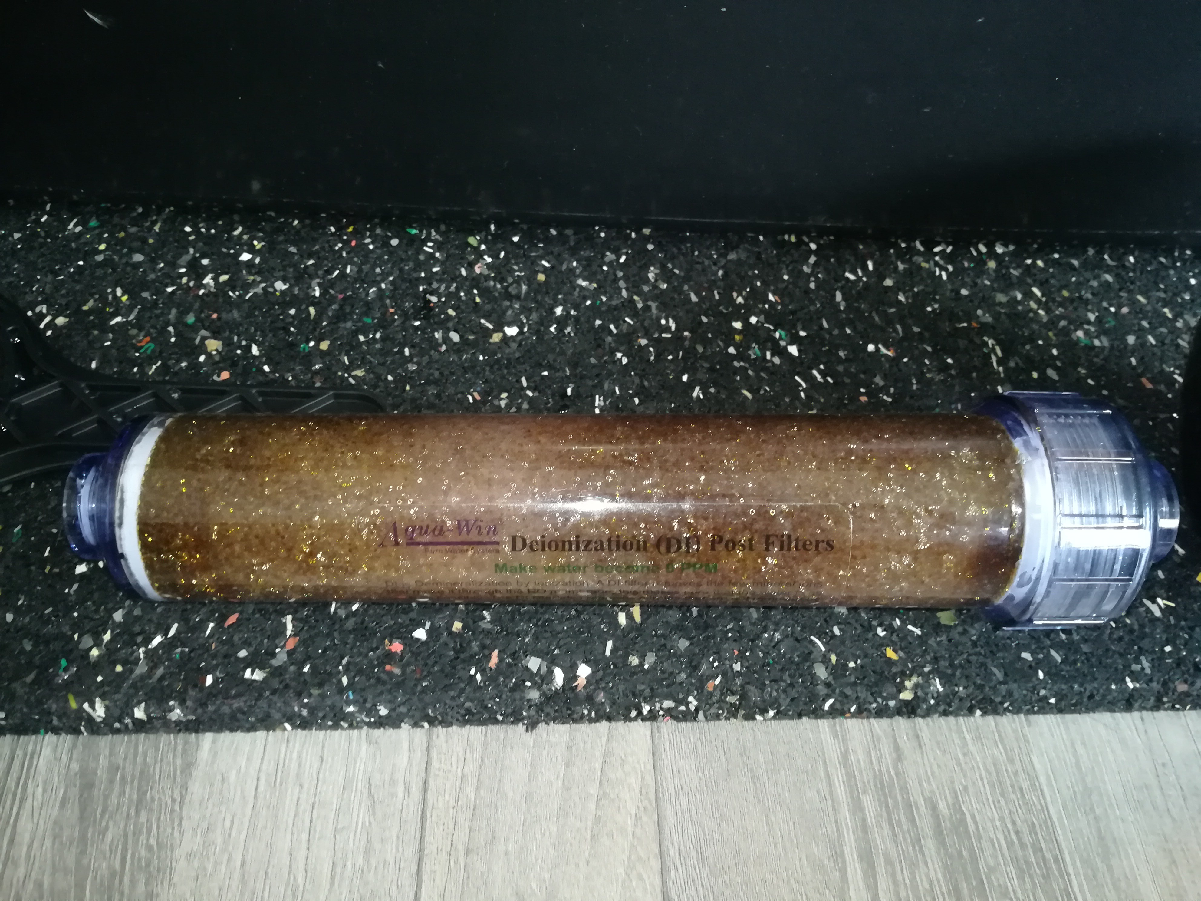
- Deionization Filter for making the water less conductive
- Some filters in different sizes for testing
- They are used to keep the water in the reservoir clean
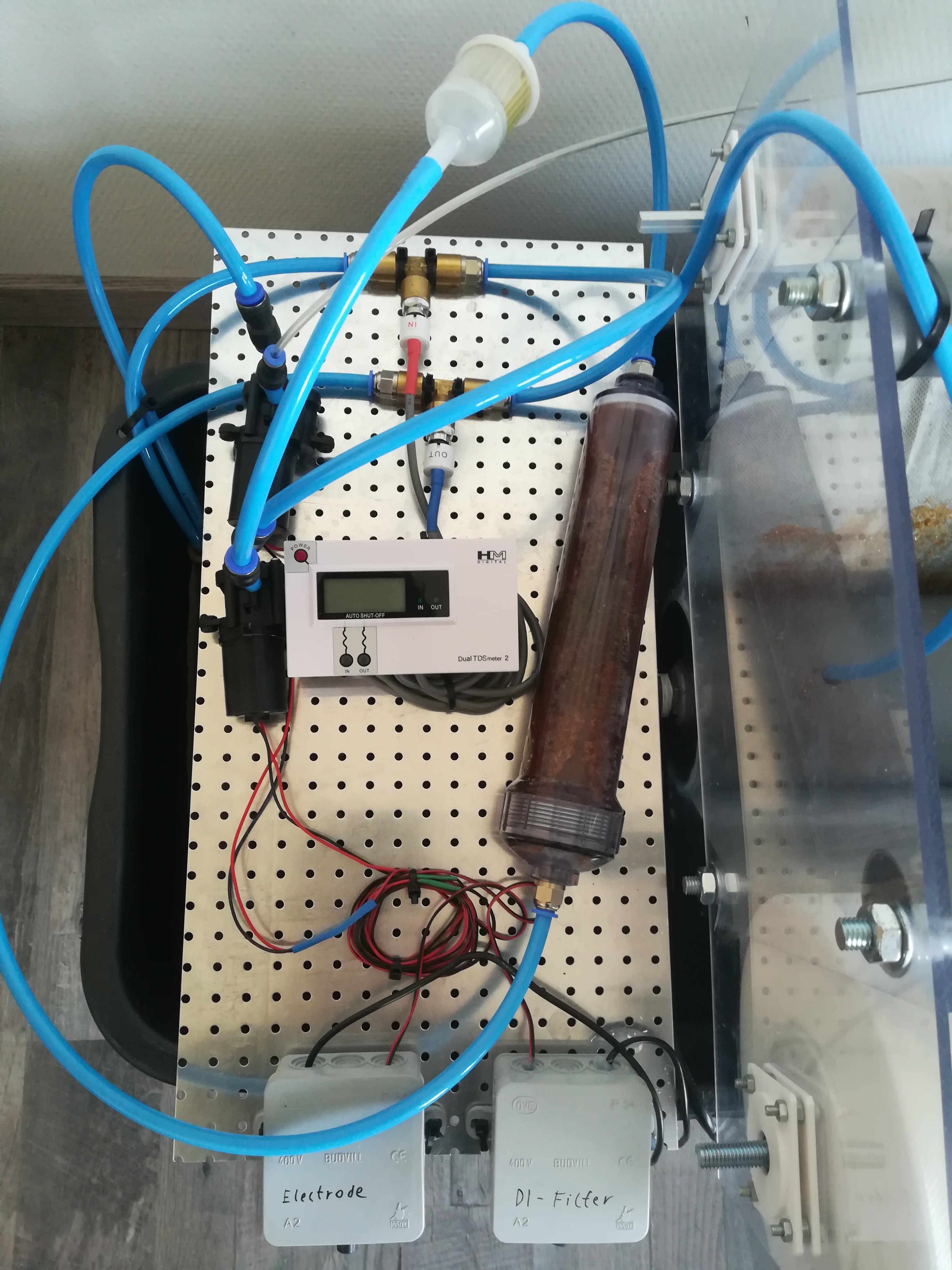
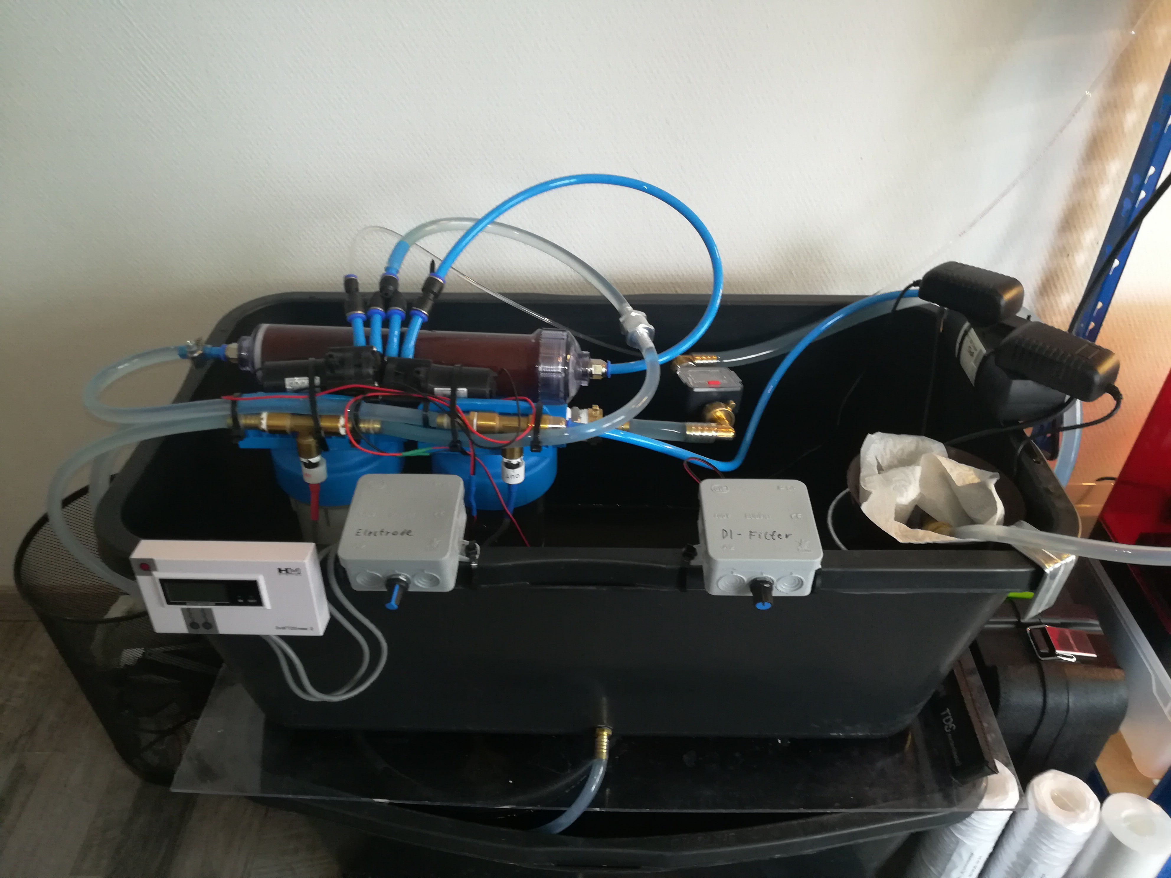
- Whole water system
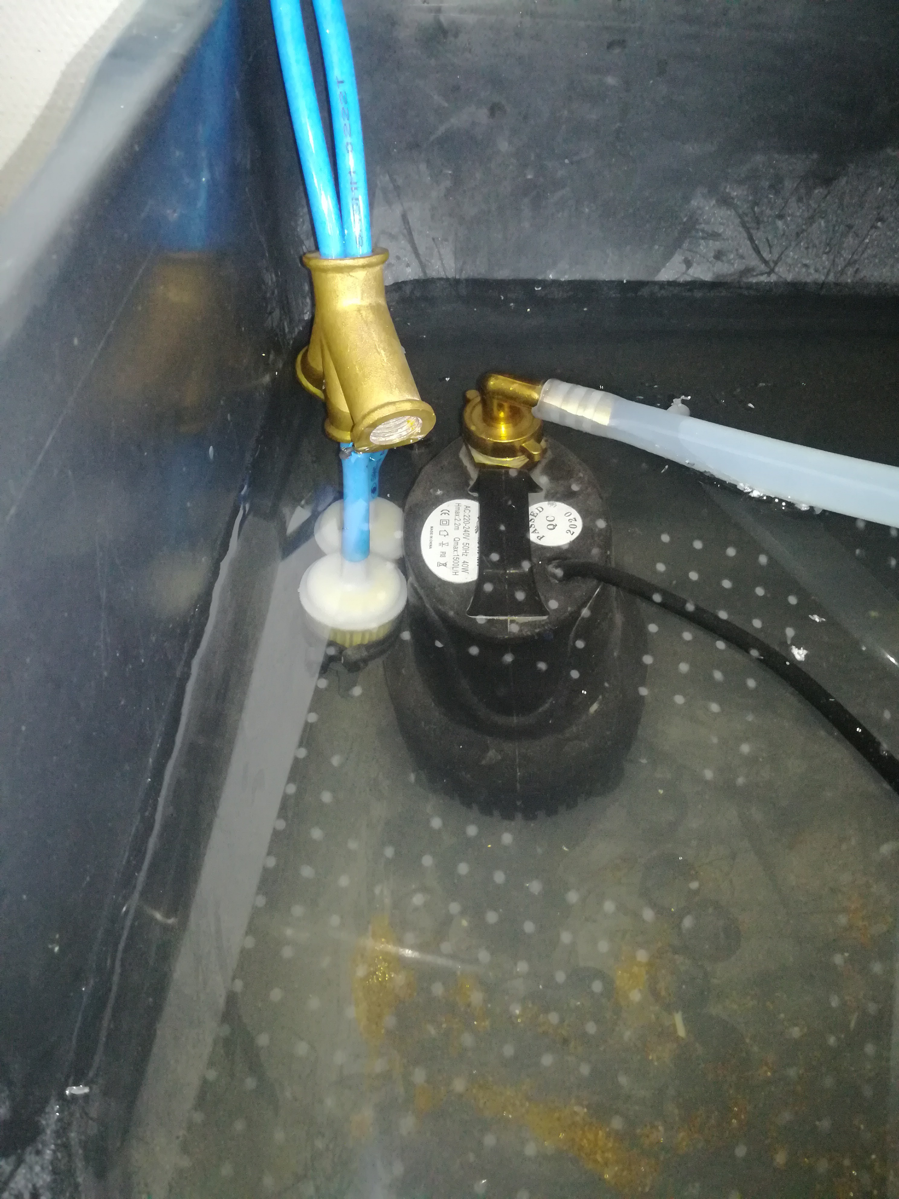
- The lower container is filled with clean deionized water and contains an aquarium pump to pump the water through a filter
- Aquarium pump
- Outlet of the DI filter (blue tube)
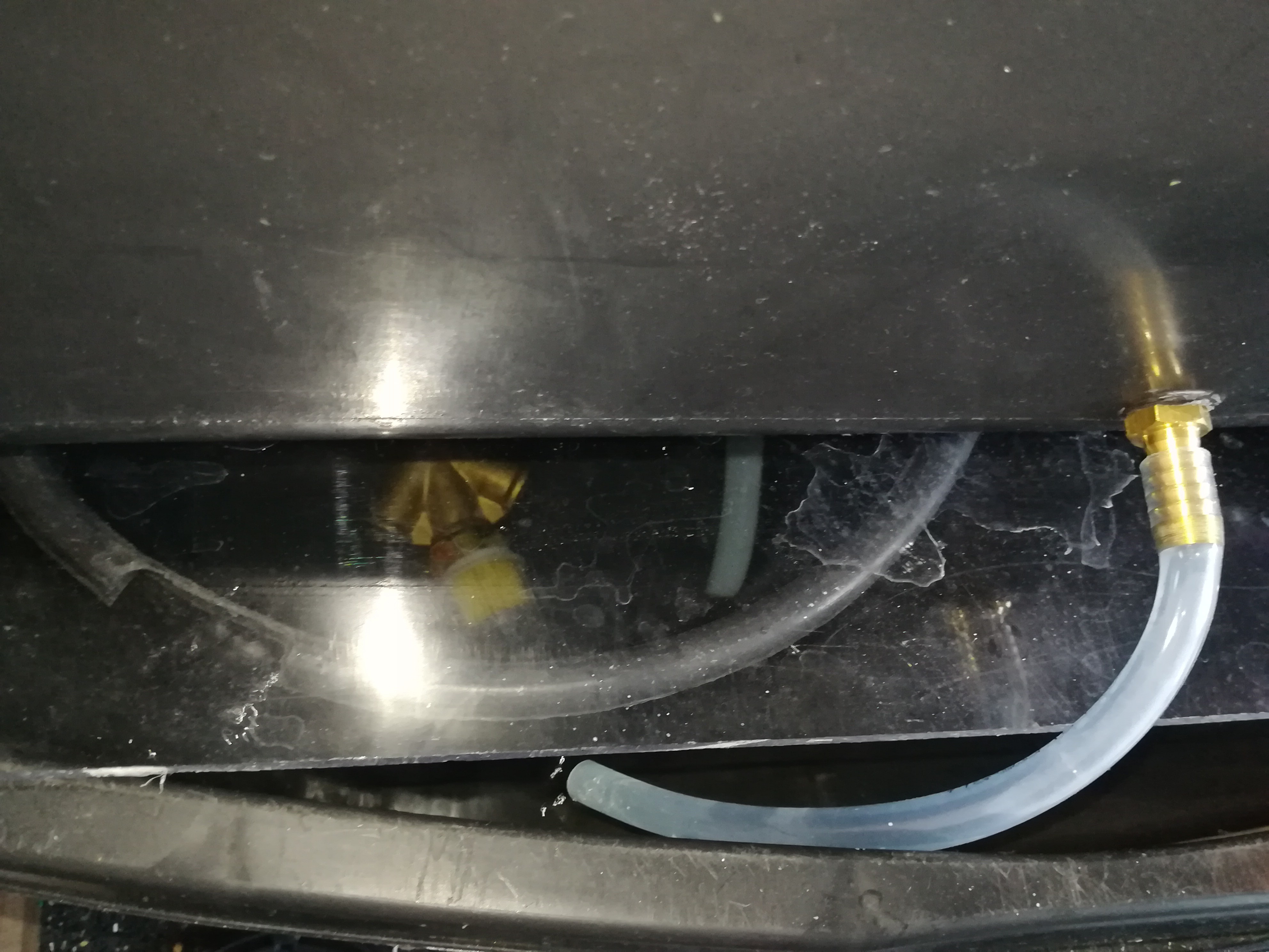
- The outlet of the cleaning filter and inlet of the gear pumps with a petrol filter and a weight on it
- Tube from the upper container to the lower container
- The upper container is used to store and mount the most parts and also to collect some of the dirt from cutting that settles down on the ground
- It has an outlet that leads to the lower container
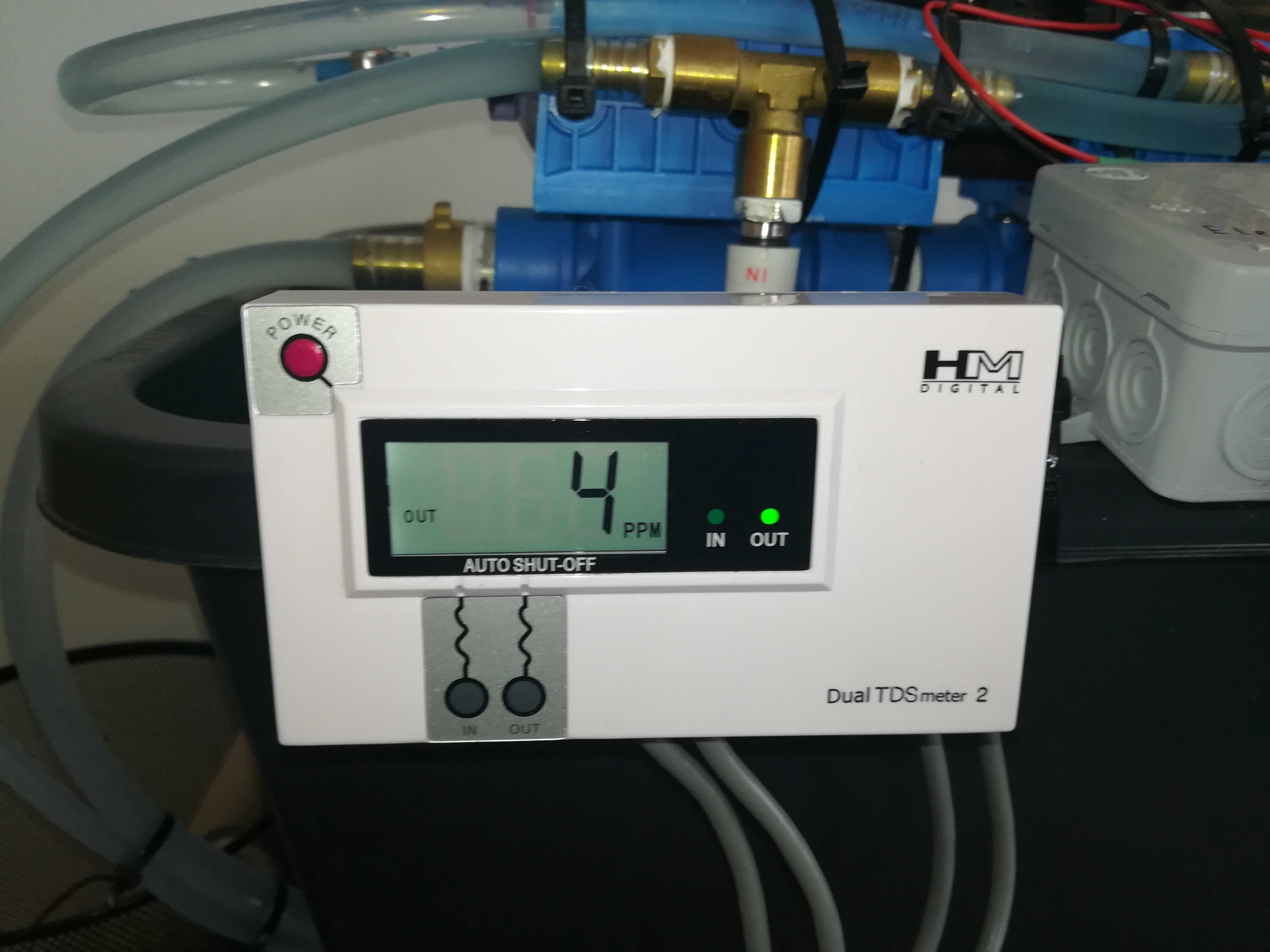
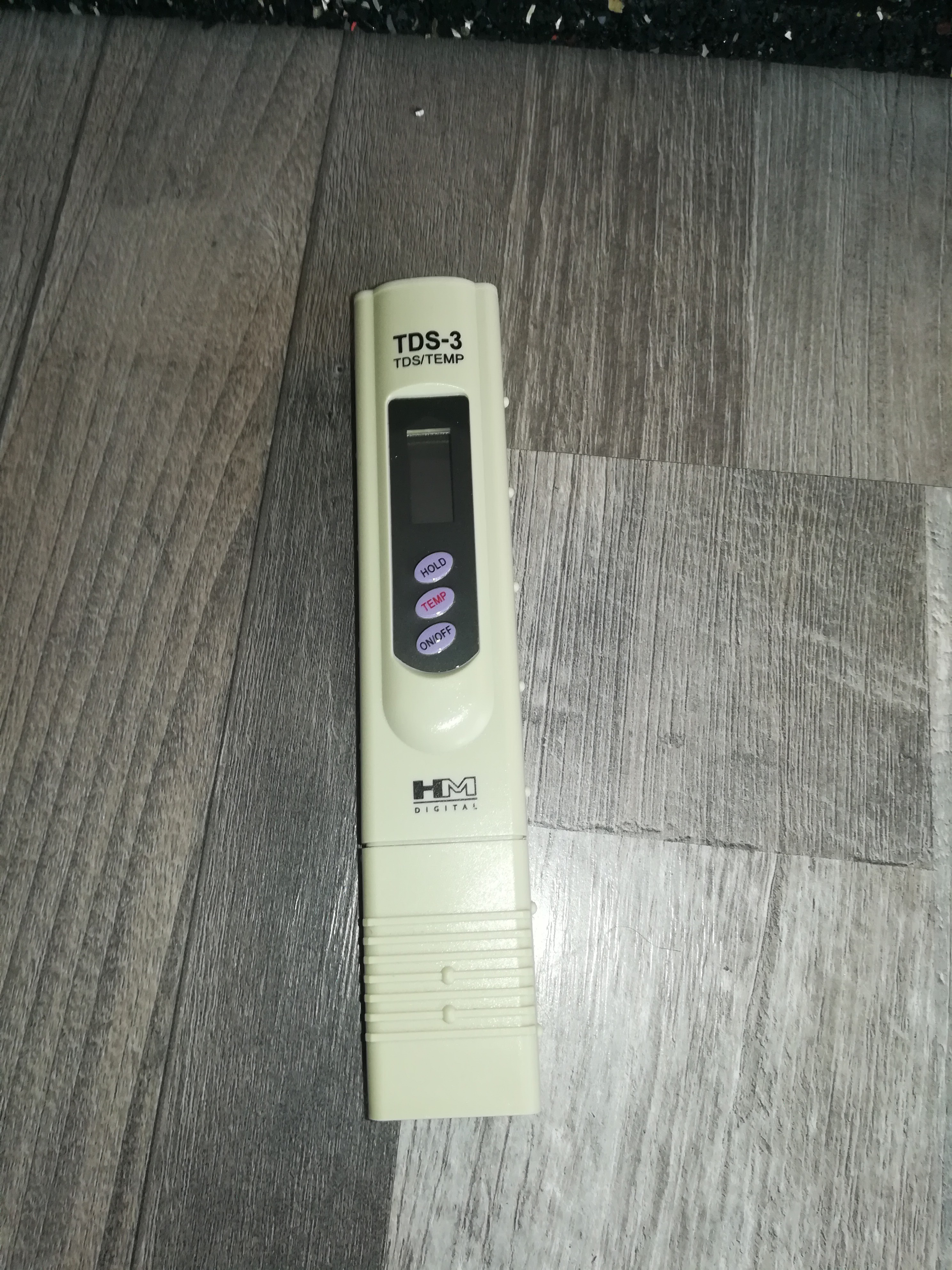
- TDS Meter to measure the conductivity on the in and outlet of the DI filter
- To check the conductivity in the system and check if the DI filter needs to be replaced
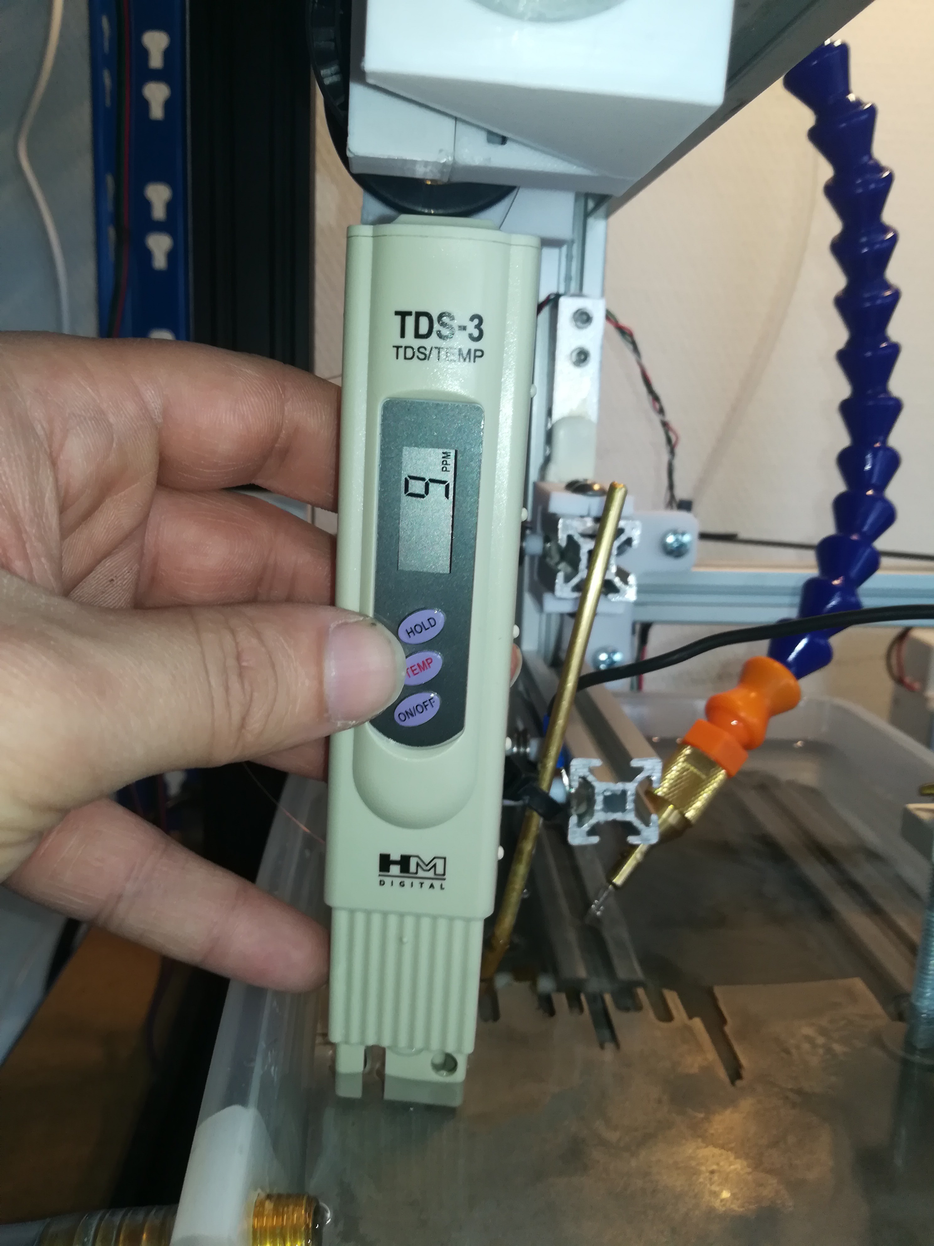
- Hand TDS Meter
- Conductivity at the EDM machine
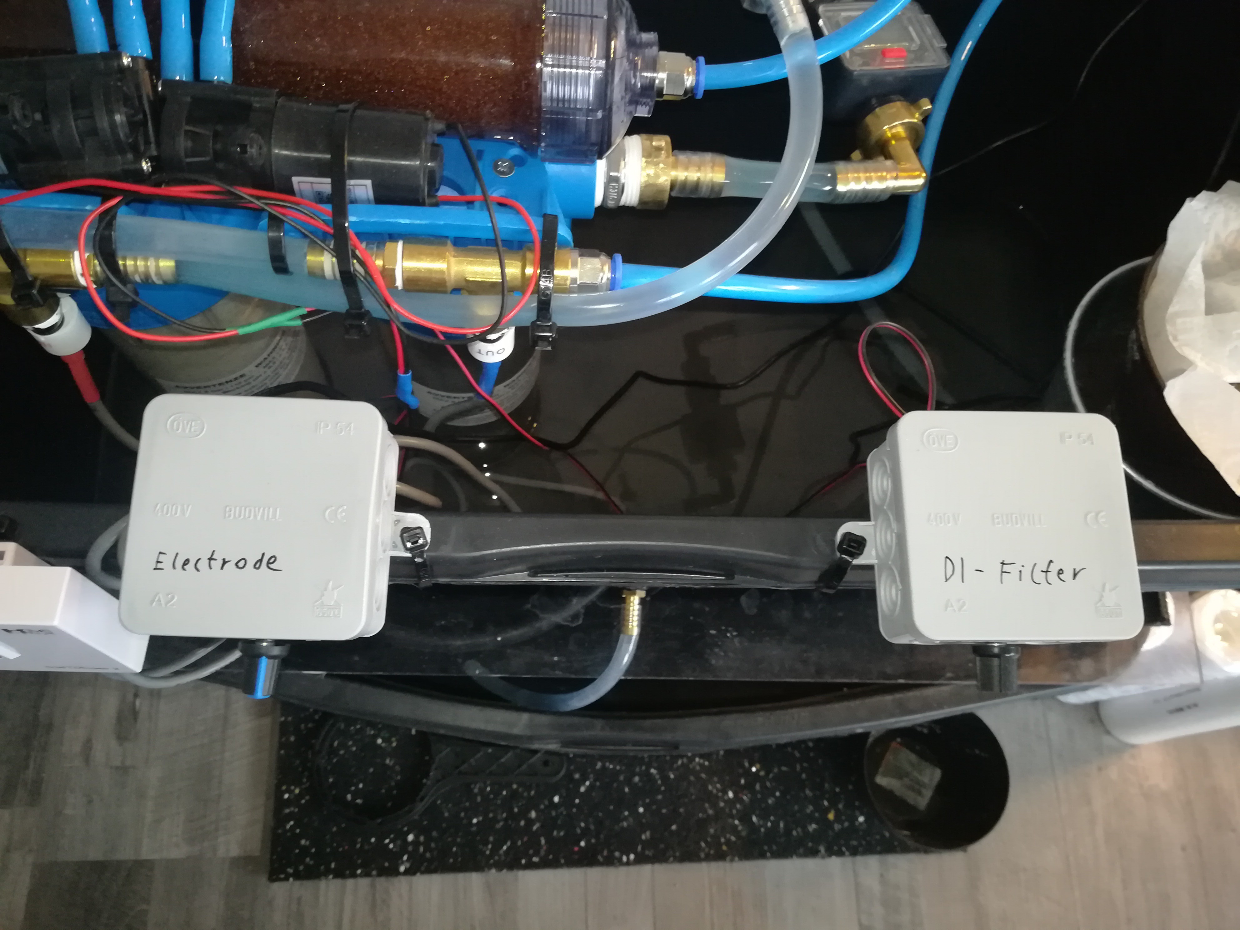
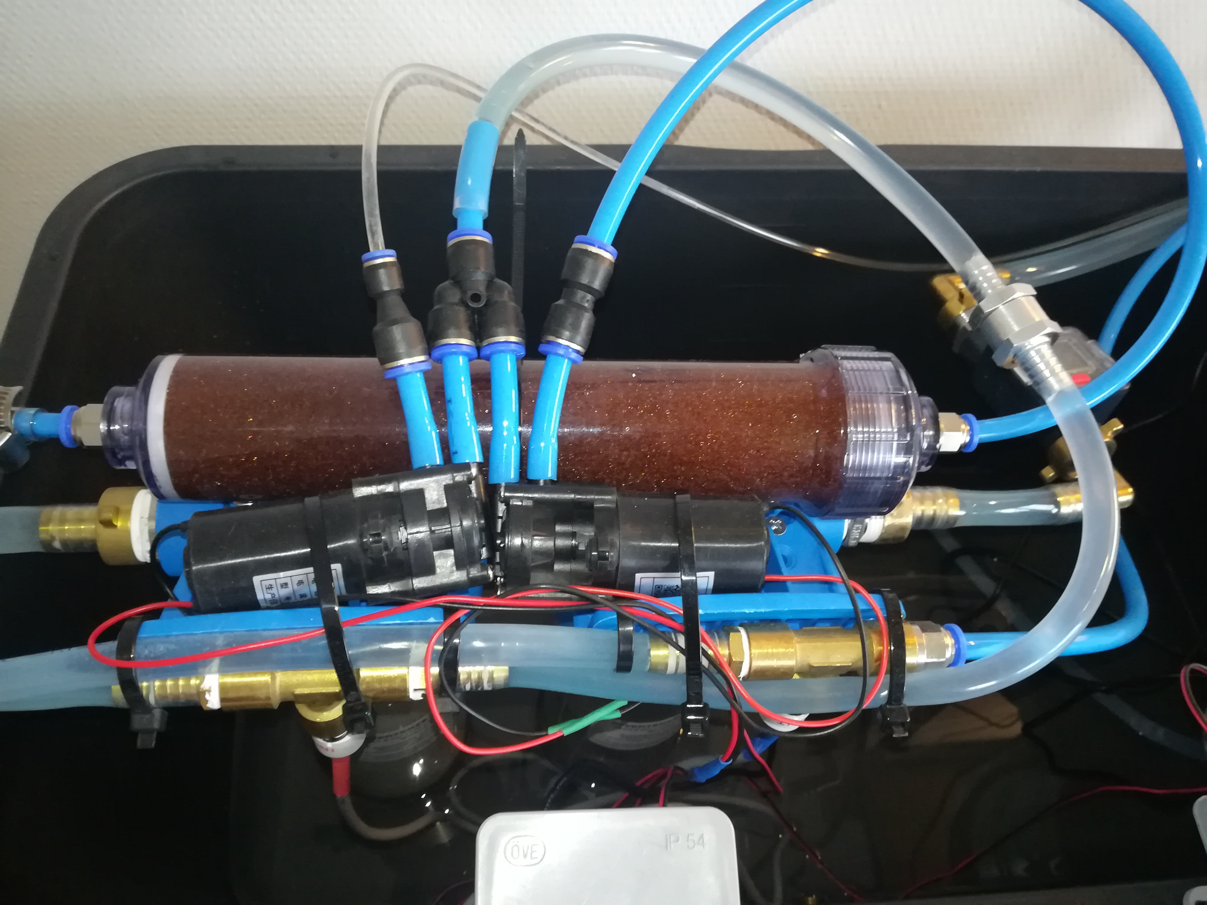
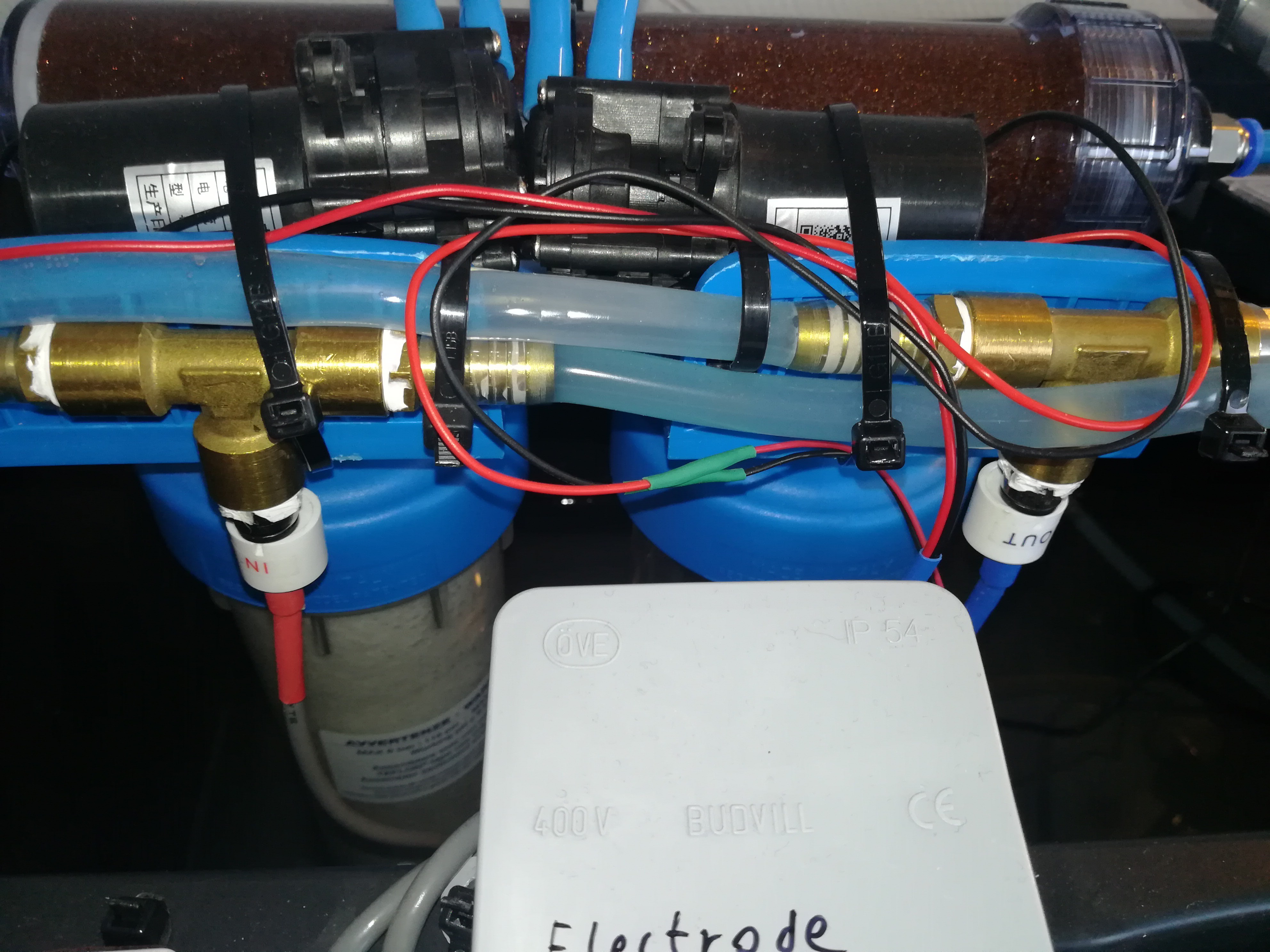
- PWM controllers for gear pumps to control flow through DI filter and to the electrode flusher
- Gear pumps with common inlet and check valve. Because for the DI filter and electrode flusher a higher pressure is needed than aquarium pumps can provide and because diaphragm pumps are too noisy, I choosed gear pumps for this.
- DI filter
- TDS sensors on in and outlet of the DI filter
- Everything is mounted on top of the cleaning filters
- Cleaning filter
- I inserted just one at the time
- TDS sensors for in and outlet
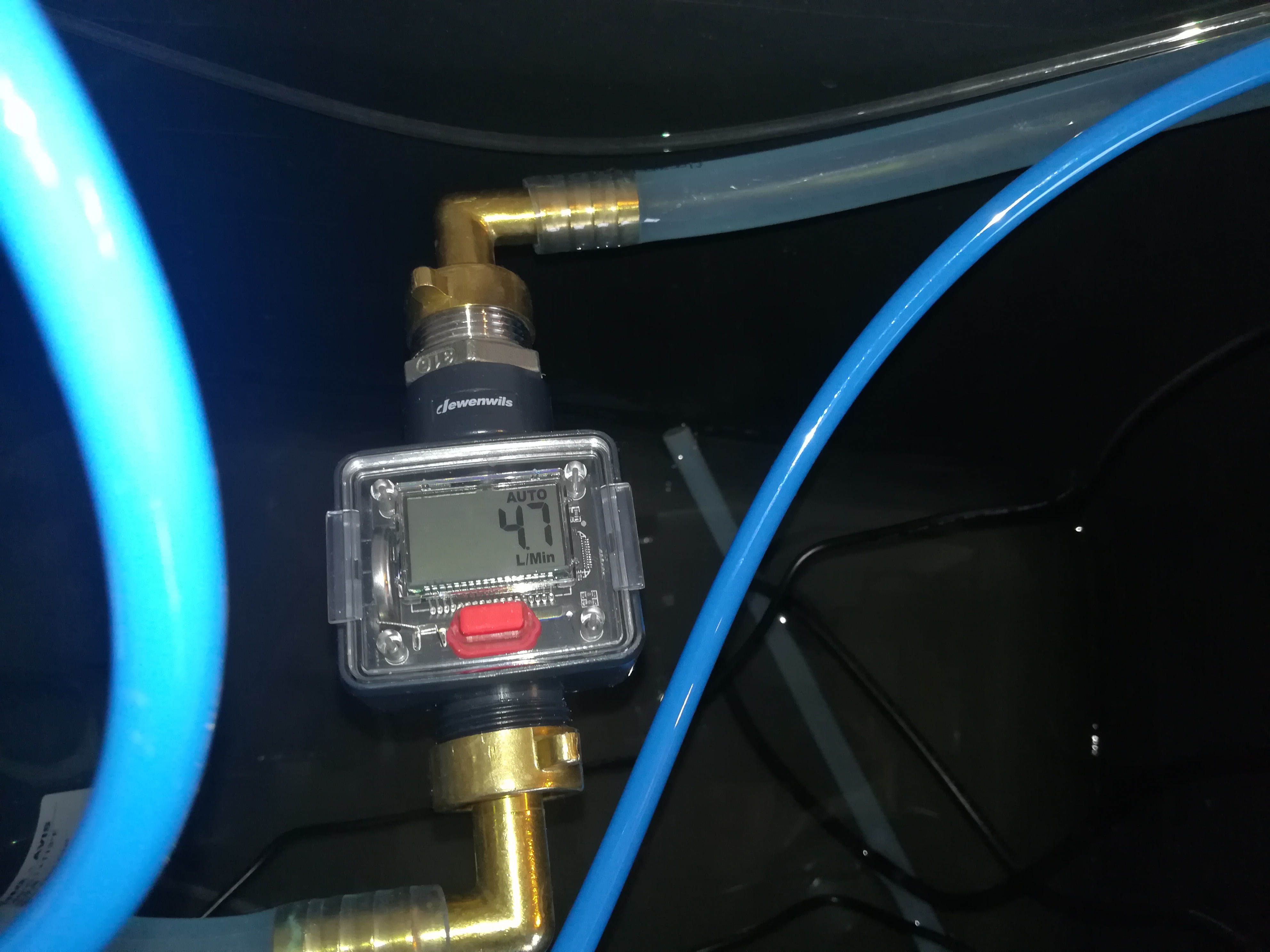
- Flow sensor for the cleaning filter to check if the filter needs to be replaced
- Outlet of the EDM machine with weight
- I used paper towels to filter out most of the dirt, but while cutting they get clogged very fast.
- I think this needs an improvement, maybe some sort of continuous paper roll that slowly rolls under a waterfall into a waste bin.
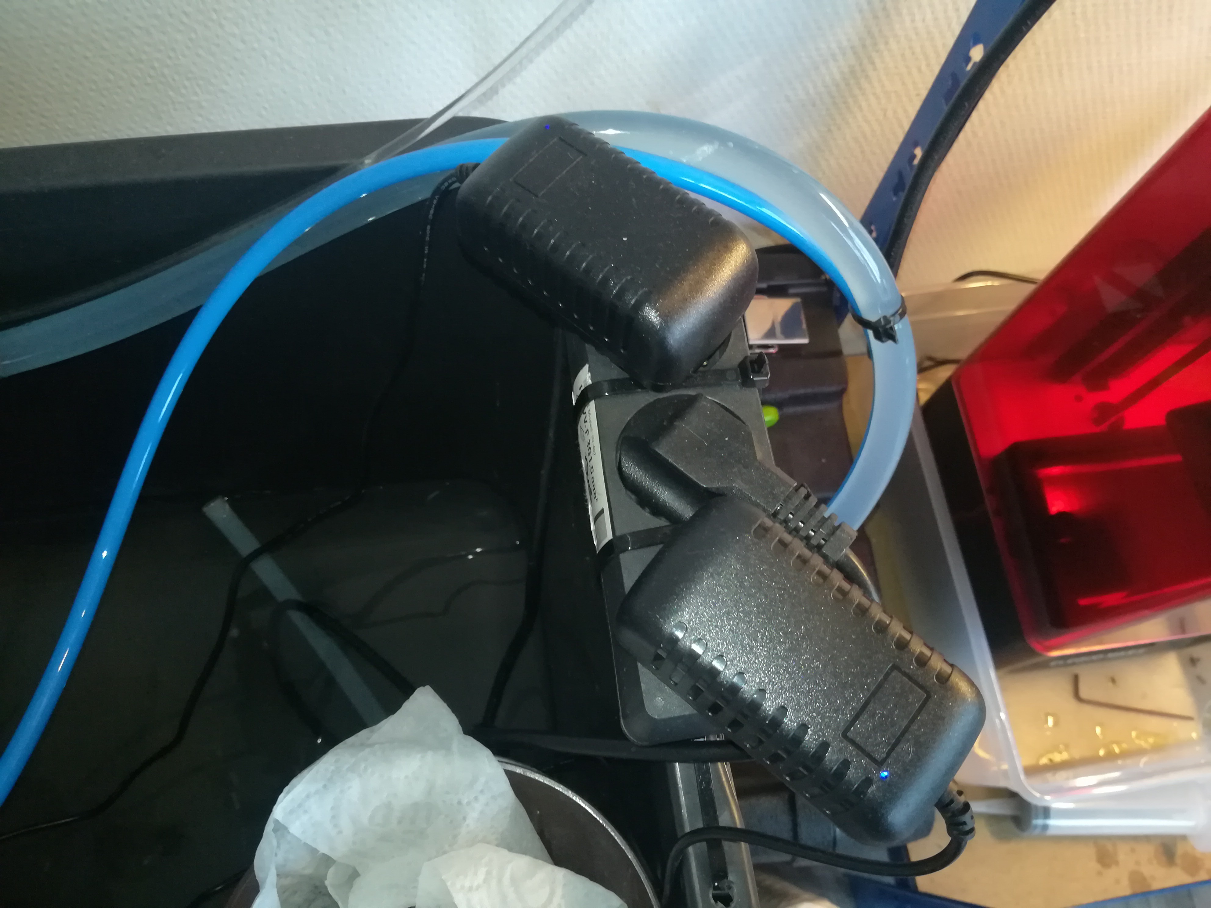
- Plug for the aquarium pump and power supplys for the gear pumps
- Inlet from the reservoir to the gear pumps
- The right pump goes to the DI filter
- The left pump goes to the electrode flusher
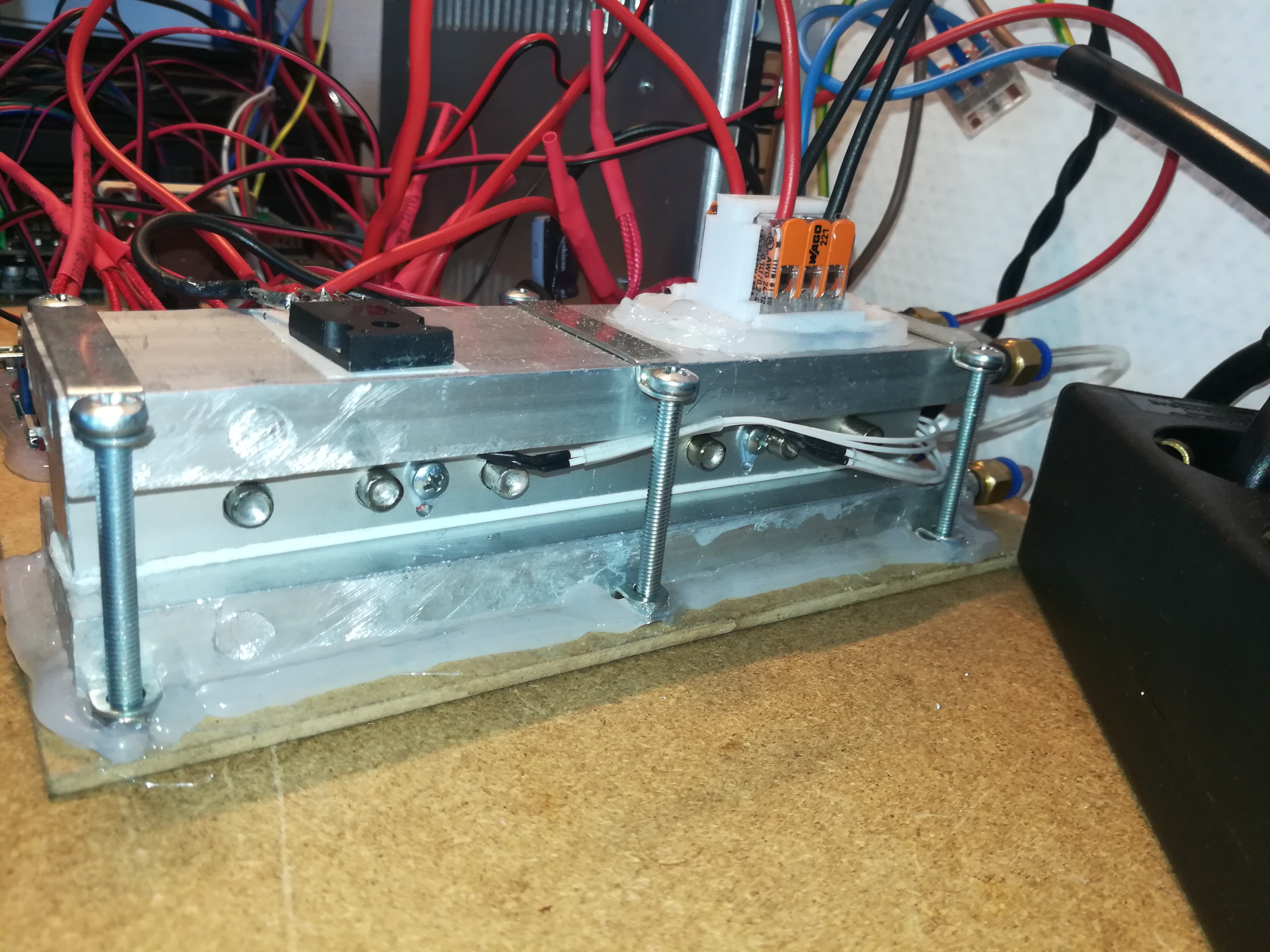
- Here you can see the cooling block for all parts that will heat up during cutting. It is placed between the gear pump and the electrode flusher
- Between two cooling elements there is an aluminum bar in which six 12V 40W heaters are placed, that are used as resistor for the arc generator circuit
- There is also a IRFP260 MOSFET placed on top of it, also from the circuit
- The temperature of the cooling block is measured with two thermistors for redundancy
- In the rare case that the cooling should fail at the time when there is a short on the workpiece what would lead to overheating of the cooling block after some time, an emergency stop would be called that would cut off the power to the arc generator circuit.
- Electrode flusher to flush out the dirt from cutting
- Outlet of the EDM machine that leads to the paper towel filter
So, that's the water system that I use for testing at the moment.
For now it's ok, but if I cut more parts in the future it will likely need some improvements to filter out more dirt before the filters need replacement.
 Dominik Meffert