-
V0.2-Mechanical and Actuation Update
10/12/2021 at 23:57 • 0 commentsSince the last update, I started looking at sourcing and standardizing some of the components, and looked at the price of doing so. Although it looked cool, the previous design required 2 beveled gears to power the wheel, and 2 bearings to support the wheel itself. A quick search on McMasterCarr found each component costs ~$5 USD. So for a robot with 4 wheels it would be ~$80 USD just for mounting hardware. Not including I was planning on implementing a servo so the wheels can control better. This prompted me to redesign the main structure for stepper motors.
Core Platform:
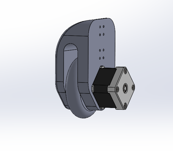
I split it up instead of 4 modular segments to 8 segments. This way the wheels and cover for protection can be separated allowing the assembly to be more modular. For rigidity there is now a second one stacked underneath it.Wheel base:
The wheels now connect directly in line with the stepper motors to not only remove the need for the beveled gears, but one of the bearings. The second bearing is used somewhere else, however removing the beveled gears should save ~$40 USD and reduce failure points.![]()
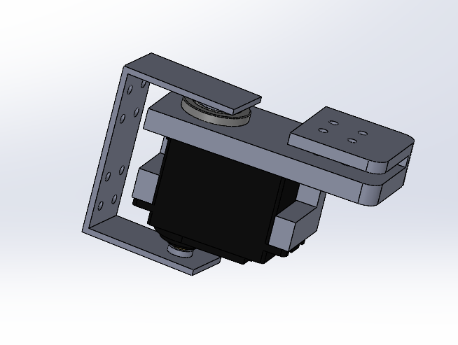
Servo Actuation:
Servos have been added on each leg so the drive train can be rotated. This allows the wheels to not have to fight friction as they were before. Another solution would be to create some omni-wheels or make it a mechanum drive. Those however, may be different modules I develop in the future. For now I feel I can learn more developing controls on an over-actuated platform.![]()
Renders:
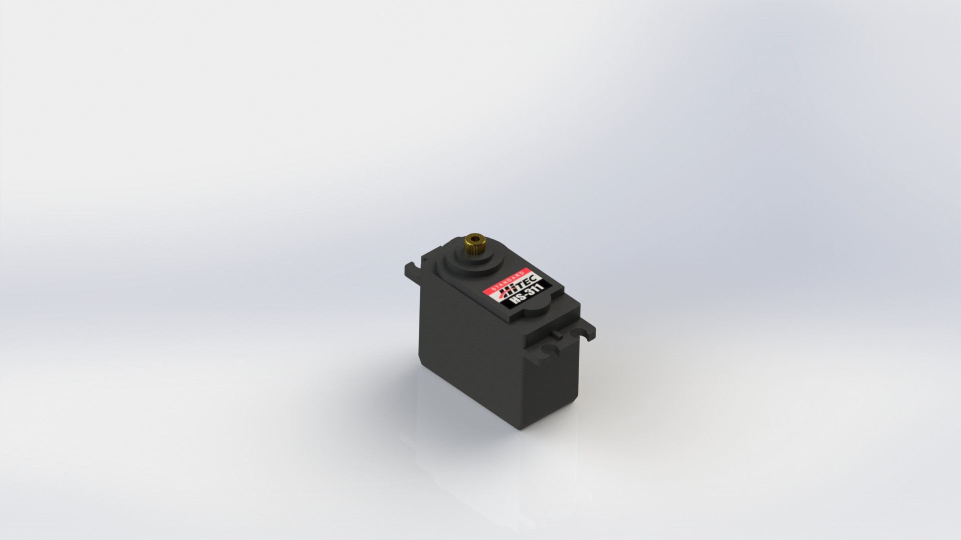
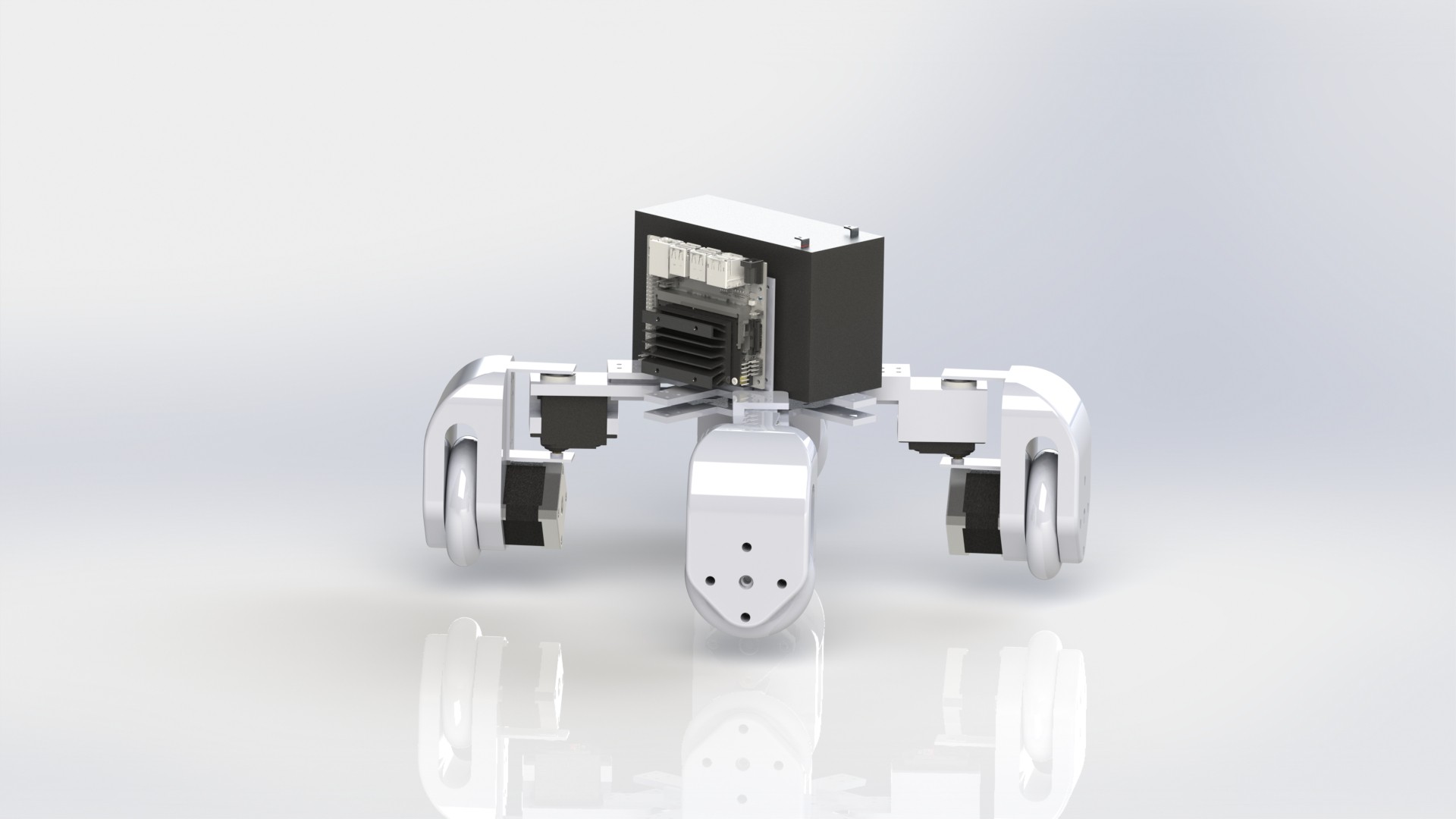
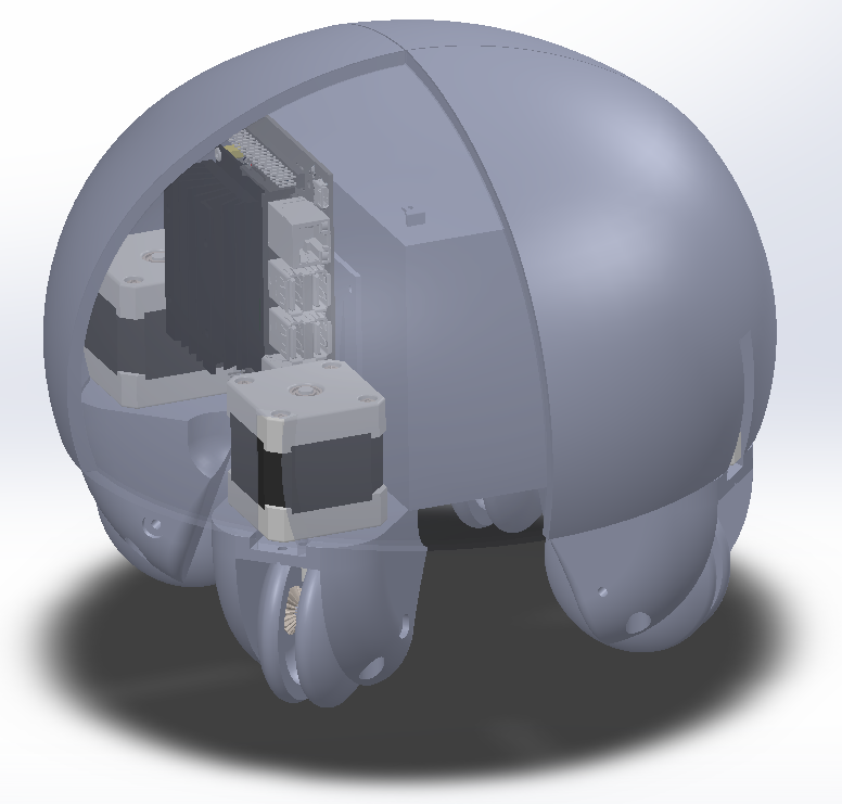
Before I was doing line renders for the system as I enjoyed the style it was in, but also because I was pretty lazy with appearance properties. I had some fun with that this time around when I went a little overkill with modeling a servo... I went back and added some textures on the battery too and made a full render of the system so far (3D printed materials in white).This time it felt like I was just deleting so much of the old progress I had made, but such is part of the design process. You cannot improve a design if you don't remove the parts that are inefficient or don't make sense. Even now, this will probably change significantly 1 or 2 more times before the "final" design gets created. And even after that once 3D printing, assembly, and testing begin a lot will be completely redesigned once again as it attempts to become reality. This project is just getting started!
-
V0.12-Motor Update
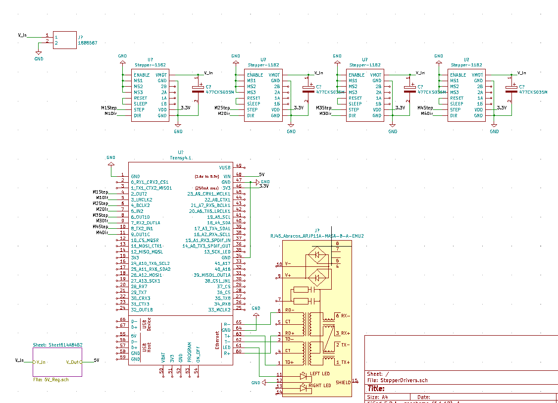
09/21/2021 at 21:03 • 0 commentsThe previous version of scrappy had a computer, and stepper motors, but no interface between them. In fact, there wasn't even proper coupling between the wheels and the stepper motor (whoops). Both of these have been added with an Teensy 4.1 added to a board with 4 socketable motor drivers.
![]()
This picture is the rough schematic for how this will work. Again these files can be found on the scrappy github under KiCad. It will first start by using the built in micro USB to transfer data, but something I want to implement is connecting to ROS over the new ethernet capabilities the Teensy now has. Note connectors to the steppers has not been done yet, I am still looking into standards that hobby stepper motors have for these connectors.
Speaking of electronics design the previous voltage regulator board's footprint needs to be changed to have a lower profile. For now this circuitry uses the same 5V regulator as the computer supply, however I am currently looking at using a higher amperage regulator for the computer .
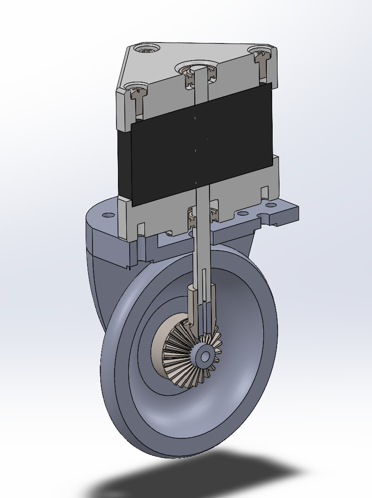
As for actual transmission of power, I have completed the gearing that are inside of the wheel mechanism. Here is an up close section view of that.
![]()
The gears for now will just be held on with set screws until I can figure out a more elegant way for this to be done.
As a note, the shell shape has been altered to reduce 3D printing time significantly and also provide more space for peripherals inside.
Thanks for reading!
-
V0.11
09/20/2021 at 03:19 • 0 commentsThis is the first alpha release of Project Scrappy. This includes all of the developed CAD files to date.
Mechanical:
The CAD files include the first structure of the system, with legs built for stepper motor for actuation. It also has a Jetson Nano mounted vertically with a SLA battery for a power source. All of this is designed to be printed on the 7"x7"x7" print bed on the Prusa Mini 3D printer. All fastening hardware is designed to be M3 bolts and nuts. Further work will be improving mounting parts, ease of assembly, and optimizing parts to be 3D printed, as the current covers would take nearly a full day to print due to the geometry.
![]()
Electrical:
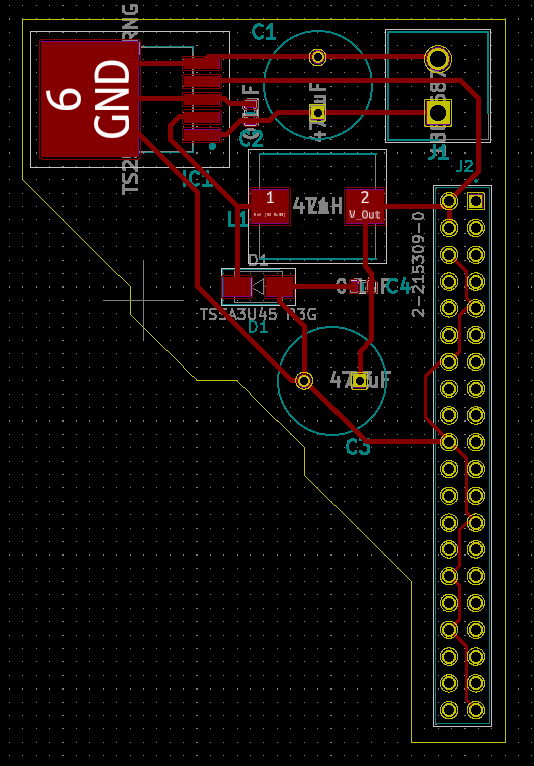
So far a simple 5V regulator to feed from the SLA battery has been created to allow for further expansion on the Jetson and Raspberry PI GPIO pins. The weird shape for the PCB is so it can be easily panelized, however with more components added the footprint will likely have to change.
![]()
Please feel free to check out the files in the github repository and suggest anything with the progress. Keep in mind this is very early on, however expect more development soon. Thanks for reading!
 Daniel Resio