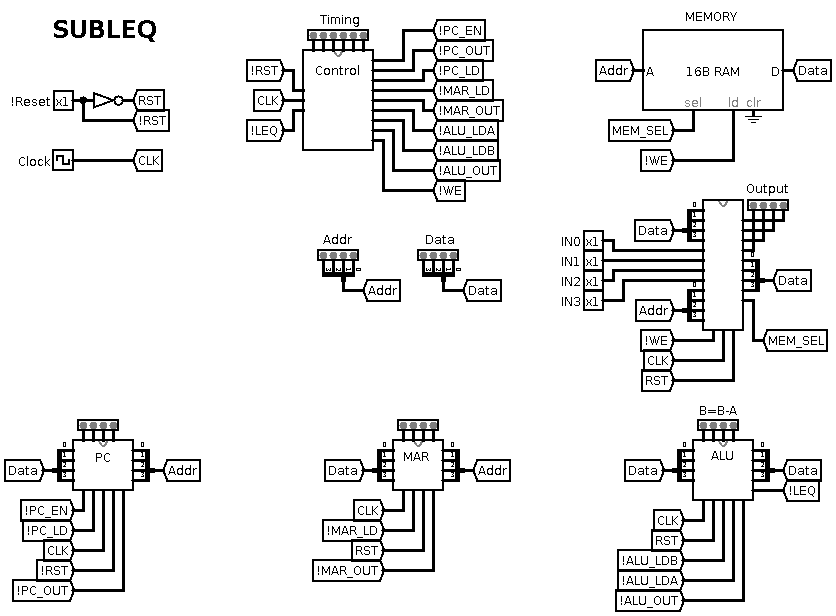
 agp.cooper
LogiSim
Basically I am using SubLEq to teach myself LogiSim.
Is it even possible to get anything useful out of a 4 bit SubLEq.
Actually, yes I can get a 4 bit counter working in LogiSim.
74XXX Libraries
You will need some external 74XXX libraries. I used 74xx Libary.circ (https://github.com/kara-abdelaziz/CHUMP-processor/) and logi7400ic.circ (https://github.com/r0the/logi7400). Did not find a library that was complete.
I found and error in logi7400ic.circ for the 74161. The clock input was inverted. I modified my version of the library to fix it. Taking down this error took many hours.
From Concept to Working Simulation
I am impressed, about 15 hours over three days as a LogiSim novice.
Structure
LogiSim encourages the user to design your circuits hierarchically. Both with "bit width" and sub-circuits. As SubLEq is difficult to understand this is a good approach.
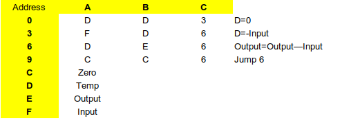
Programming SubLEq
Here is the binary counting program I am trying to implement:
| Address | A | B | C |
|
|
| 0 | 0 | 1 | 3 | Z = 0 |
P = 1 |
| 3 | 1 | 0 | 6 | Z = -1 |
|
| 6 | 0 | F | 9 | B = B + 1 |
|
| 9 | 0 | 0 | 3 | Z = 0 |
|
| C | 0 | 0 | 0 |
|
|
| F | 0 |
|
|
I/O |
|
Usually address -1 or in the case 0xF serves as Input/Output or output in this case.
Note: A write to the I/O address also write the value to memory.
SubLEq has only one instruction:
- Mem[B] = Mem[B] - Mem[A] and jump to C if the result is Less or Equal to zero.
Decoding the Binary Counter Program
Address Comment
0 0,1,3 ;Set up Z (=0) and P (=1)
Usually this is written:
0 0 1 ? ( ? means the very next address)
3 1 0 ? ( 1 is the count increment, set Z = -1 )
6 0 F ? ( Increment the output address 0xF )
9 0 0 3 ( Reset Z = 0 and jump to address 3 )
C 0 0 0 ( Not reachable but: Reset Z = 0 and jump to address 0 )
F 0 ( The I/O address )
I am sure you all got the above and can now program in SubLEq.
Where to Start?
The timing diagram. I can do this because I have a bit of an idea what the sub-system look like:

Lets put this into steps:
| Timing | Micro Code | Clock |
| T0 | MAR=M[PC] |
|
| T1 | ALU_A=M[MAR] | PC++ |
| T2 | MAR=M[PC] |
|
| T3 | ALU_B=M[MAR] |
|
| T4 | M[MAR]=ALU_OUT; !WE; | PC++ |
| T5 | IF (LEQ) THEN PC=M[PC] ELSE PC++ |
|
Don't be misled, although I present a linear process, it is still iterative.
The ALU
The ALU is fairly simple:
Subtract: B = B - A
Flag: !LEq
Therefore we need:
- Load A: !ALU_LDA
- Load B: !ALU_LDB
- Read B - A: !ALU_OUT
And because of the type of control logic I am using:
- Clock: CLK
- Reset: RST
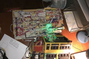
Here is my schematic:

Chip Count:
- 2x 74HC173
- 2x 74HC283
- 1x 74HC04
- 1x 74HC125 (the inverter and tri-state output buffers)
The beauty of LogiSim is that you can test the sub-circuit before proceeding.
Program Counter
The program counter is perhaps the simplest sub-circuit to design. Note: the outputs PC0-3, these are for debuging LED display in the top level:

Note: the 74161 in the logi7400ic.circ library has the clock inverted. I have edited my version of the library.
Memory Address Register (MAR)
The idea behind the MAR is to load a value from memory and then use that value as an address to load an indirect memory value. Thus it is a form a indirect addressing.

Note: the MAR0-3 outputs are for debugging.
Output
Output for SubLEq is a little tricky,...
Read more »


 zaphod
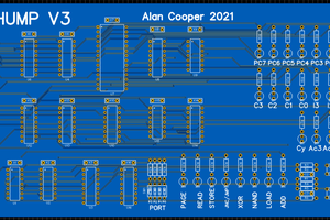
 ammarbhayat28
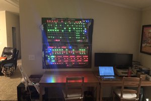
 spudfishScott
Thanks Michael,
Subleq is horrible - Don't do it!
---
A much more interesting and powerful and yet not yet finished, is my CHUMP V5.
Useful with only 4 bits!
It need a Load Effective Address (swap PC/ACC?) and Von Neumann architecture (self programmable, swap memory banks?).
Regards AlanX