Refer to the UART basics, and the component source.
When it comes to converting parallel data to serial format, an idea of shift register comes to mind, and this is how often such circuits are implemented. However, with start / stop / parity bits, the shift register must be longer than the data, and with parallel data already buffered, the number of register bits doubles.
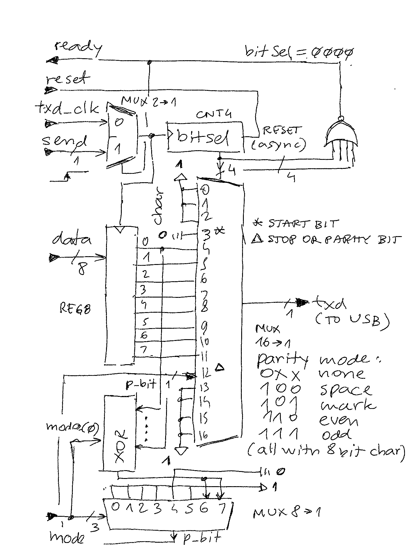
This component uses a simple MUX instead, and a 4-bit counter (bitSel). Operation is as follows:
- Reset clears bitSel
- if bitSel is 0000, the clock input is MUXed to "send" input signal
- external circuit presents data at the input and on rising edge of "send":
- bitSel is incremented to 0001
- char is loaded from data (input data is free to change after this)
- now that bitSel is != 0000, the clock is MUXed to baudrate
- as bitSel is incremented with baudrate frequency, the 16-to-1 MUX presents the right output to TXD (1, 1, 1, 0, char(0)... char(7)...)
- after char(7), the next bit depends on parity mode if selected
- finally a stop bit is transferred to TXD (this is simply MUX input driven to '1')
- when bitCnt reaches 1110, it is reset to 0000 and the circuit is ready from step 2 above
When bitCnt = 0000, it can also be used as a ready signal for the higher level circuit, meaning par2ser is idle and waiting to be loaded with data to transmit.
Main clock is baudrate * 1, which is the speed at which TXD MUX needs to change inputs. The operation mode is given by 3 mode bits:
| mode | data length | parity | frame length |
| 0XX | 8 | none | 10 |
| 100 | 8 | space (0) | 11 |
| 101 | 8 | mark (1) | 11 |
| 110 | 8 | even | 11 |
| 111 | 8 | odd | 11 |
Here is a rough (but pretty accurate) sketch of the circuit. It could be implemented in less that 10 74XX TTL ICs.

 zpekic
Discussions
Become a Hackaday.io Member
Create an account to leave a comment. Already have an account? Log In.