Close
0%
0%

NEOPIXEL and Arduino Scoreboard for School

a simple scoreboard made with NeoPixels and an Arduino Nano for Basketball and to learn programming

Similar projects worth following
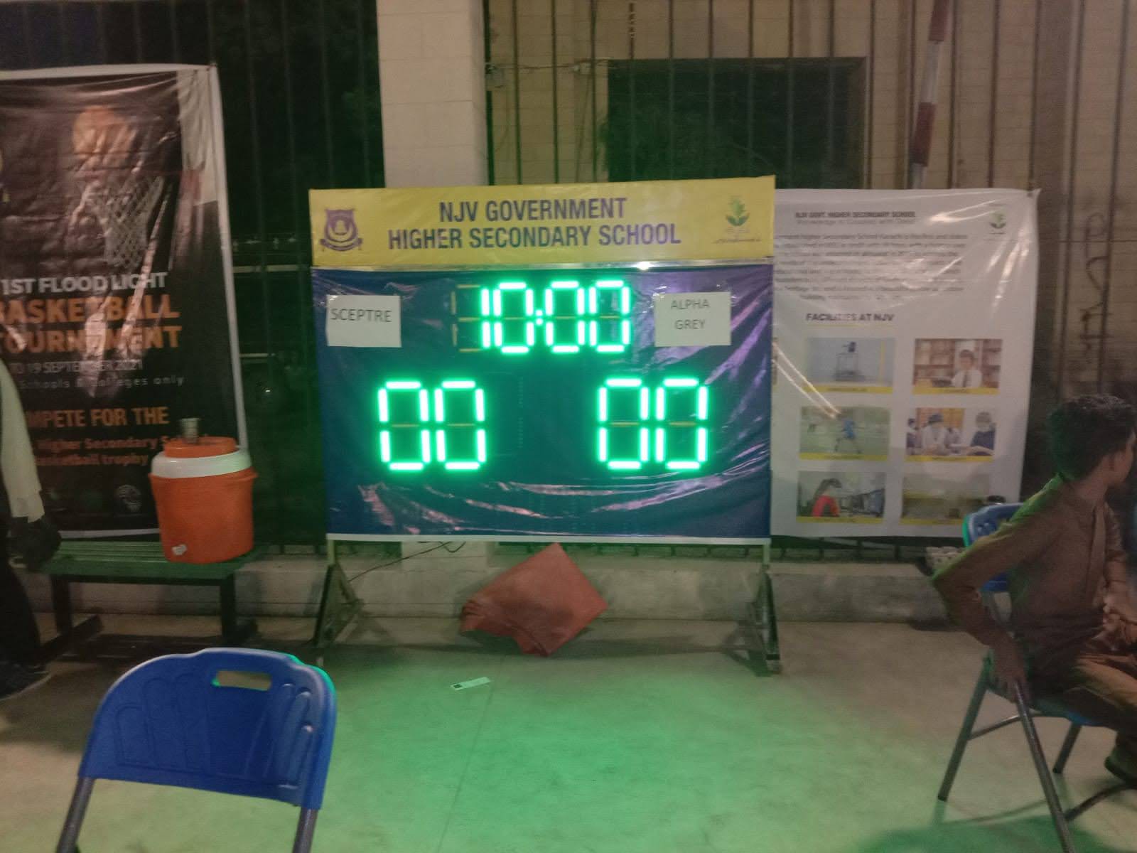
The school where I work at, had a basketball tournament, we needed a scoreboard, so we made one.

While making this board, developed a few simple functions to control each segment of each digit to sets of 2 digits to show numbers

We realized a few issues as we were showing leading ZEROs which was confusing, so that was removed.

Also created a very simple API which runs on SERIAL to modify any and all aspects of the display, color, digits, start/stop timer and much more.

the code is all available on this hackaday.io project page

STRANGE ISSUE - cause by less RAM

A strange issue arised when we added more digits, the Arduino just wouldn't work, it turns out each NEO-PIXEL uses 3 bytes in SRAM - in the end we had about 8 digits in total and around 450 LEDs, so that required a minimum of 1350 bytes in SRAM to keep the colors - the Arduino NANO we were using has only 2KB of SRAM.


As we did not have MEGA atm, we fine tuned the code, removed most of the SERIAL.PRINTLN lines, and the ones we wanted to keep, we used the F("STRING STORED IN FLASH") macro inside the SERIAL.PRINT functions and finally the code was running like it should.


HOW TO WORK WITH YOUR NEO PIXEL 7-SEGMENT

The code has initially a 2D array of INTS which is the start and end of the NEO PIXEL LED numbers for each segment of each digit.

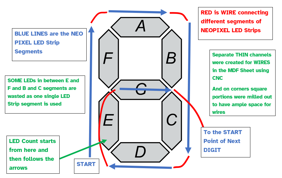
The way we wired the segments was not according to the segment order, A,B,C,D,E,F but in the code you can put in numbers for each digit in proper order and it works, any digit can be big or small the code can manage different sized digits and there is ability to have 2 digit sets.


MAKE YOUR OWN

While making your own such a scoreboard, make sure to first do a test with a simple prototype.

The code is all available, it works, but there can be a lot of improvements

More accessories can be added to Arduino, like a buzzer etc - a bigger Arduino - MEGA is more preferred, if you have more than 400 NEO PIXEL LEDs to control.

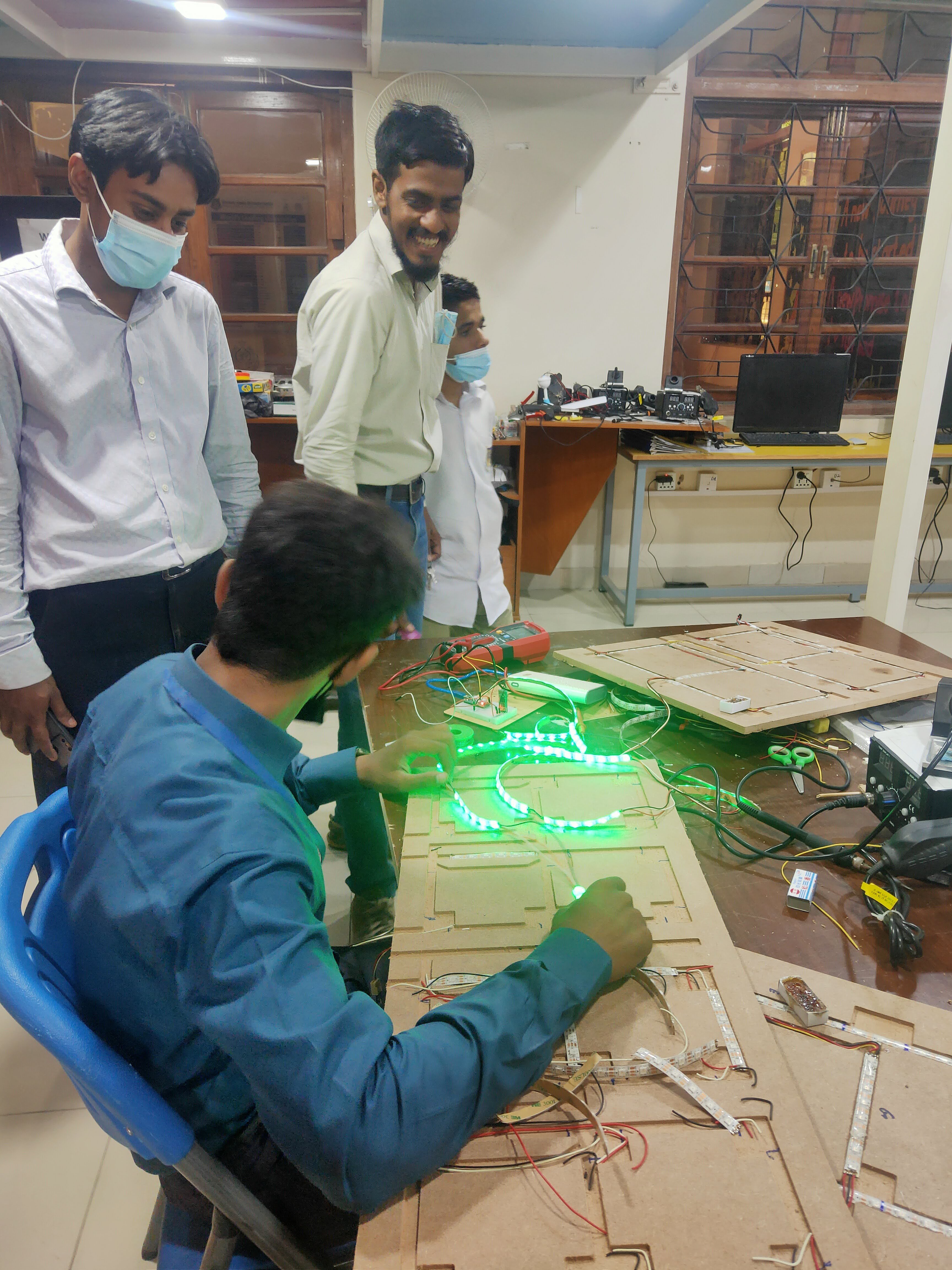
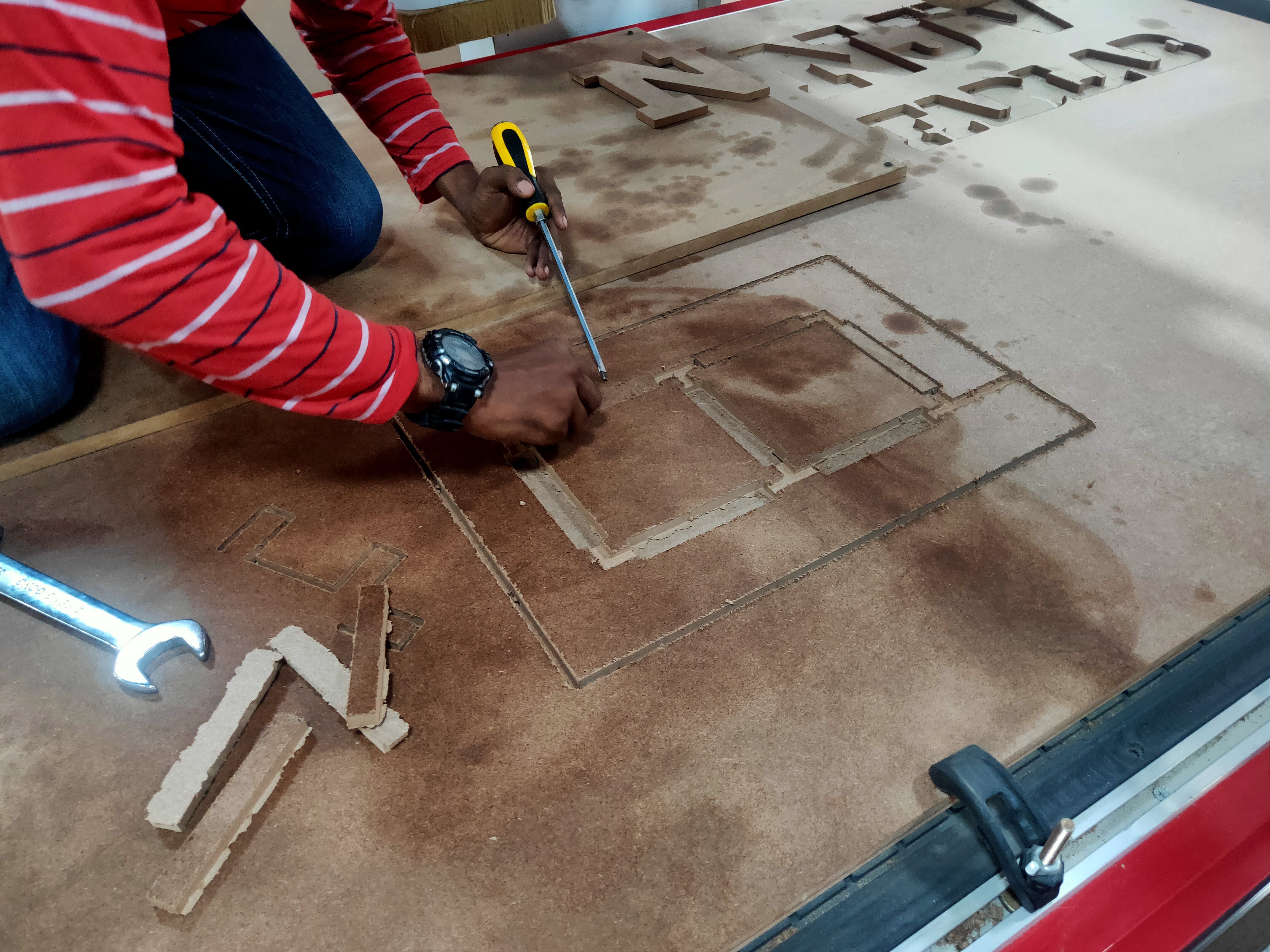
We had a lot of help from our team and we used what was available and not wanting to buy anything from outside. We have a FabLab and a CNC so that helped :) but similar work can be done with a LASER cutter as well to mill the space for LED Strips and Wires and to cut the Digit Holes on the Top side sheet.

ghanta-ghar-board-arduino-code-and-libraries.zip

x-zip-compressed - 938.76 kB - 02/17/2022 at 07:00

Download

scoreboardV3.ino

latest code, used in the tournament - has support for changing color, more digits and timer - can be controlled by serial and bluetooth

ino - 11.21 kB - 09/18/2021 at 11:51

Download

scoreboardV2.ino

v2, with dynamic addressing for pixels and more digits support added

ino - 6.28 kB - 09/18/2021 at 11:51

Download

scoreboard.ino

the first code file - testing digit and neopixel working

ino - 2.58 kB - 09/18/2021 at 11:50

Download

  • 3 × NeoPixel LED Strip Roll, 5 meter
  • 1 × Arduino Nano
  • 1 × Bluetooth HC-06 Module
  • 1 × PC Power Supply
  • 1 × CNC Cut 7-Segment Display Frames

View all 6 components

  • Let the GAMES begin

    ZaidPirwani09/18/2021 at 12:11 0 comments

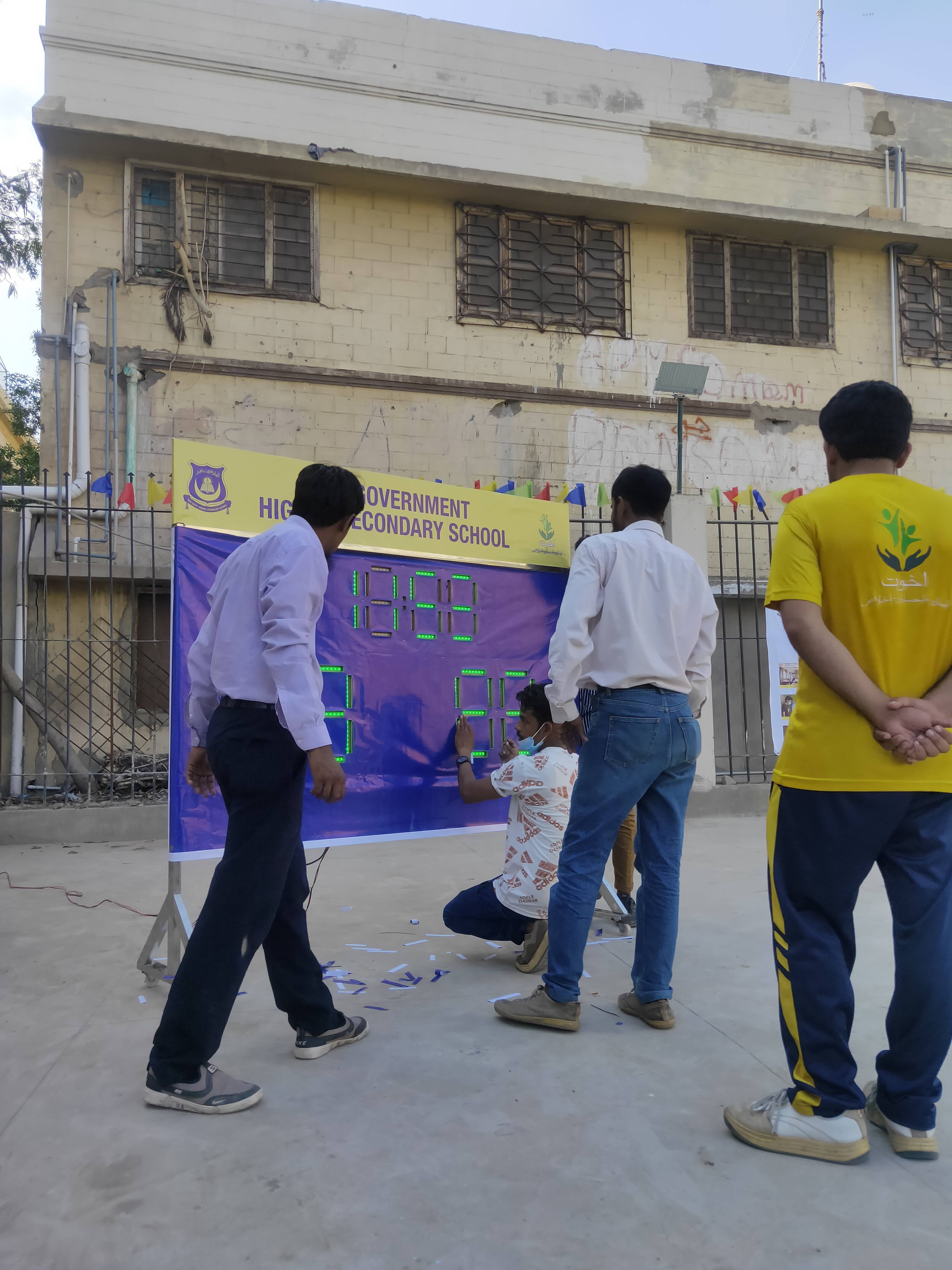
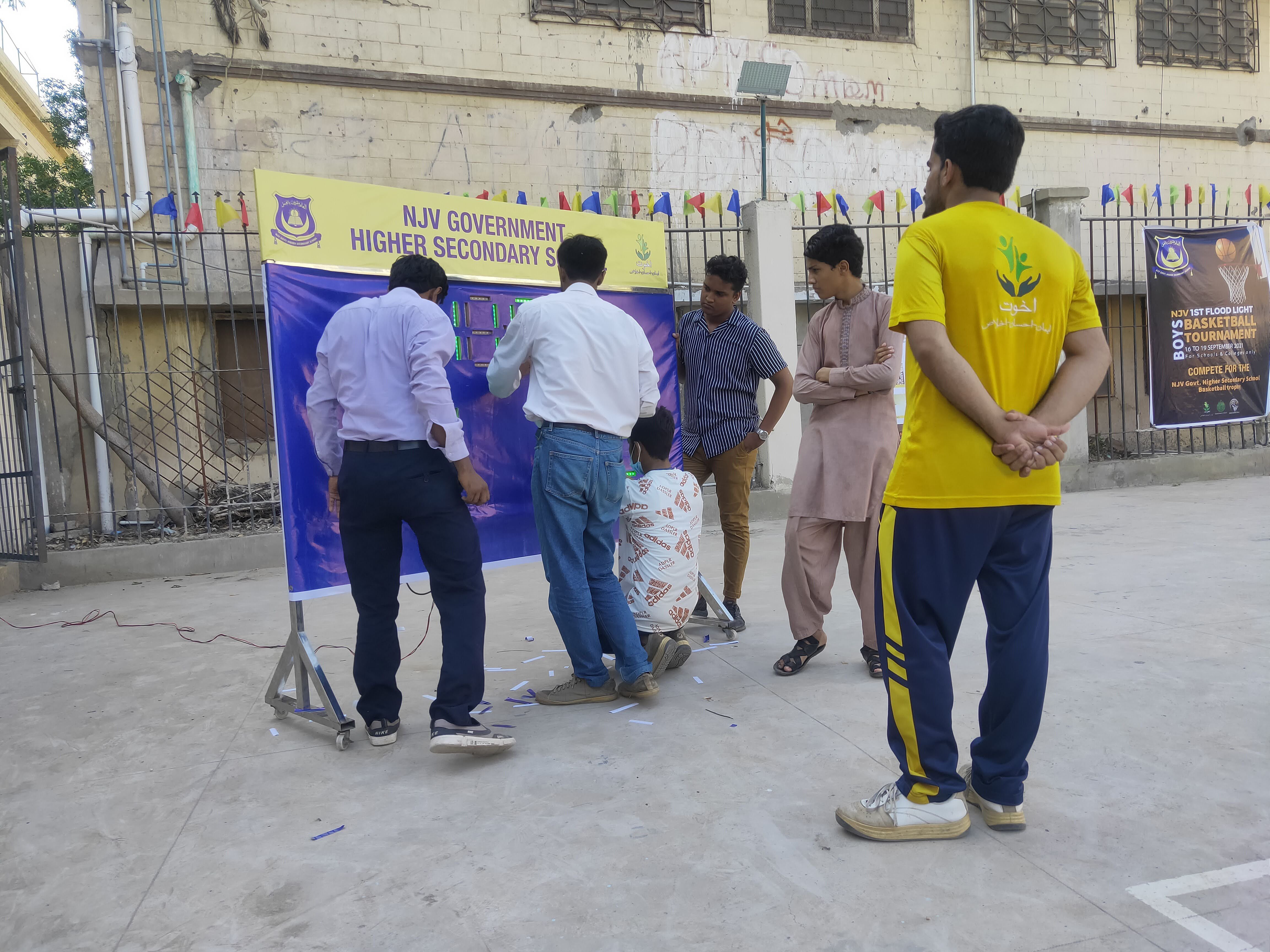
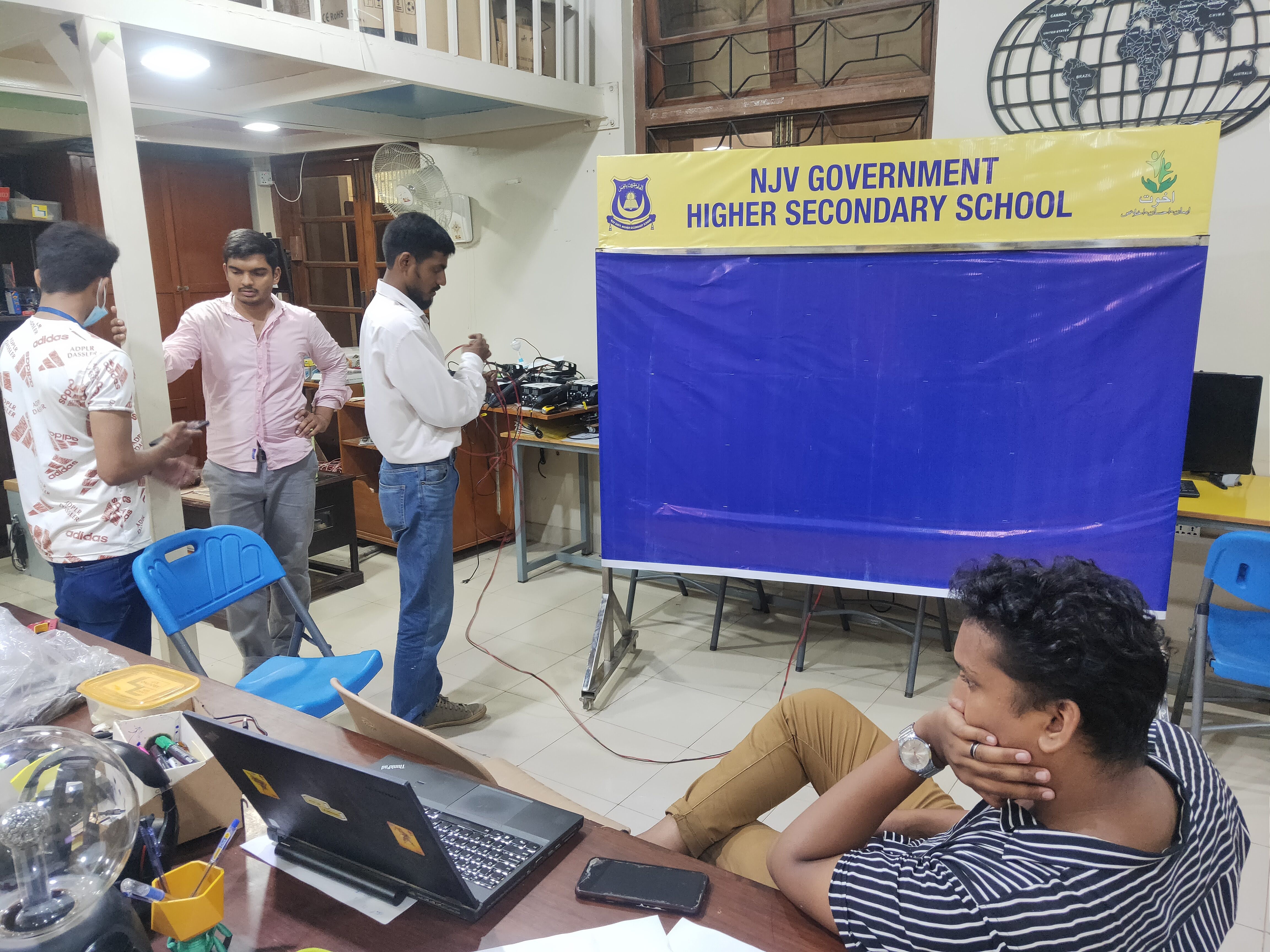
    We attached everything to a plywood sheet, we attached the sheet to an old metal stand, we got all the help we needed from our awesome team members, students and interns.

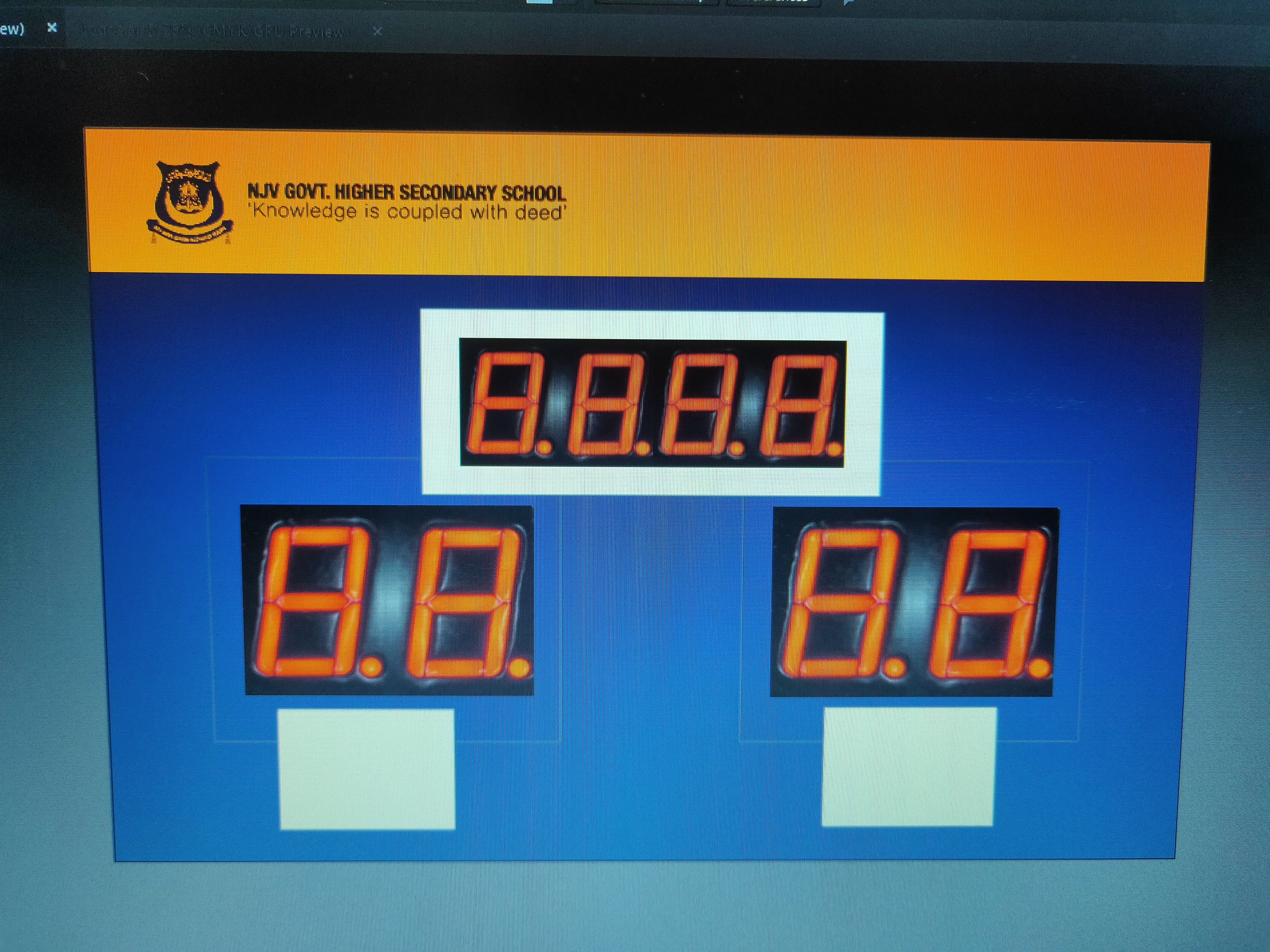
    Panaflex poster was printed with a simple background and header, attached to the board and then later digits were cut, panaflex was tightly held by stapler pins using a stapler gun.

    Using BLUETOOTH SERIAL TERMINAL app https://play.google.com/store/apps/details?id=de.kai_morich.serial_bluetooth_terminal&hl=en&gl=US we can control the score, time and color using SIMPLE api methods


    L# to add score to left, small letter l to decrease score, similarly for other digits we used the other alphabet codes

    R for right side, M for minutes, S for seconds and T1 to stop and start the timer.

    Added some bonus funtionality, timer turns RED on the last minute

    X1, Y1 and Z1 commands change color to Red, Green and Blue.

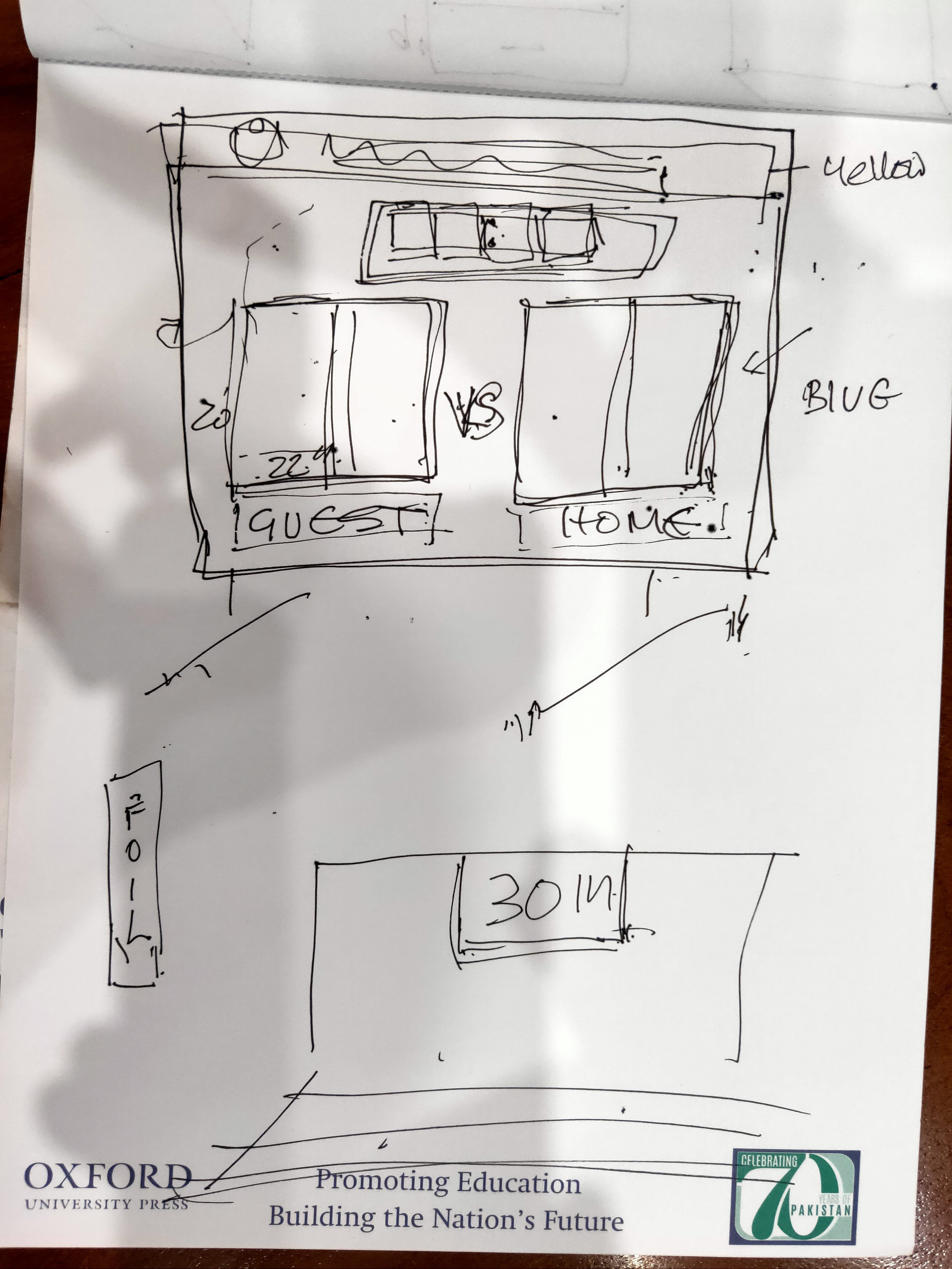
    in Future, we need to add FOUL indicator for both teams, quarter indicator and also a loud siren noise.

  • More Digits...

    ZaidPirwani09/18/2021 at 12:05 0 comments

    After successful testing, we made more digits, 2 pairs of 2 digits for team score, 4 digits for a timer and then we brainstormed a simple scoreboard layout and got to work.

  • FABLAB for the WIN​ - make it ourselves

    ZaidPirwani09/18/2021 at 11:59 0 comments

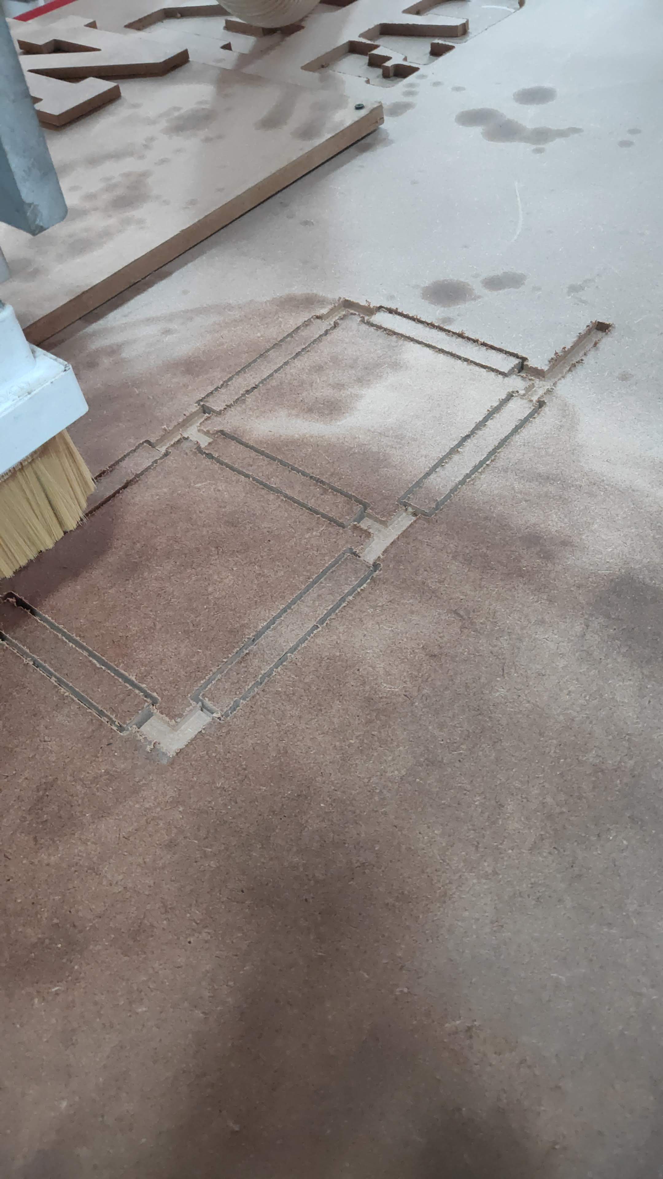
    Ultimately, we started to work on it and make one ourselves using the NJV FabLab, CNC Machines and available components and parts.

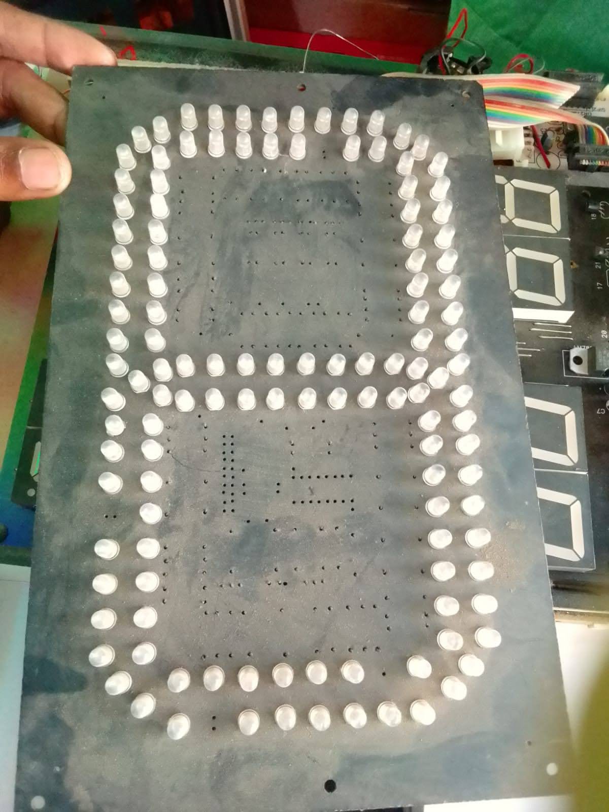
    We used MDF Sheet and cut 1 digit to test it and to also check visibility in daylight

  • Buying a pre-built Board

    ZaidPirwani09/18/2021 at 11:57 0 comments

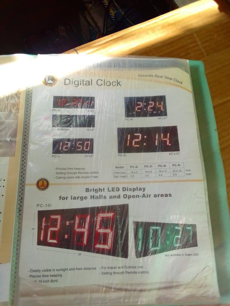
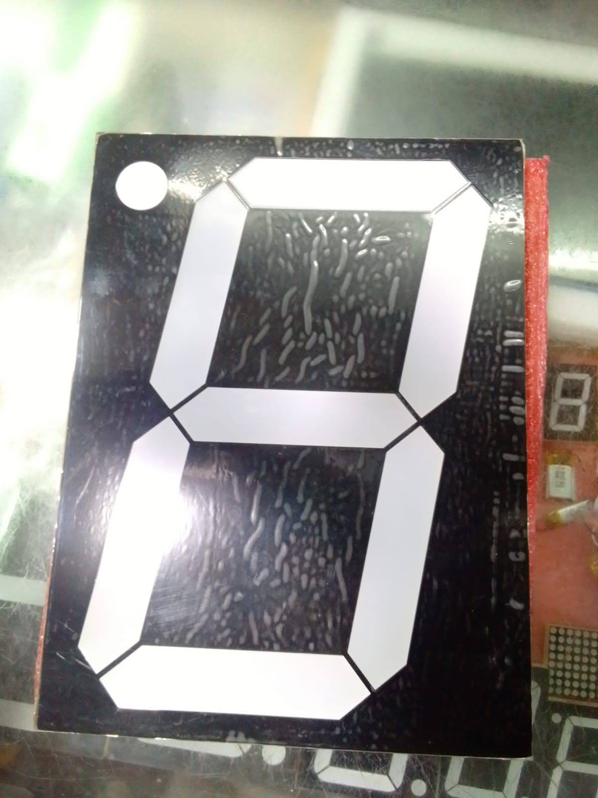
    Next we tried to buy large digits and a pre-built board from the market, we did not like the quality and the price was high and there were no features and no coding to be done.

    So we did not go with this approach.

    Price was around around 5000 Rs and more for large segments

  • Projector as Scoreboard - FAILED by SUN

    ZaidPirwani09/18/2021 at 11:55 0 comments

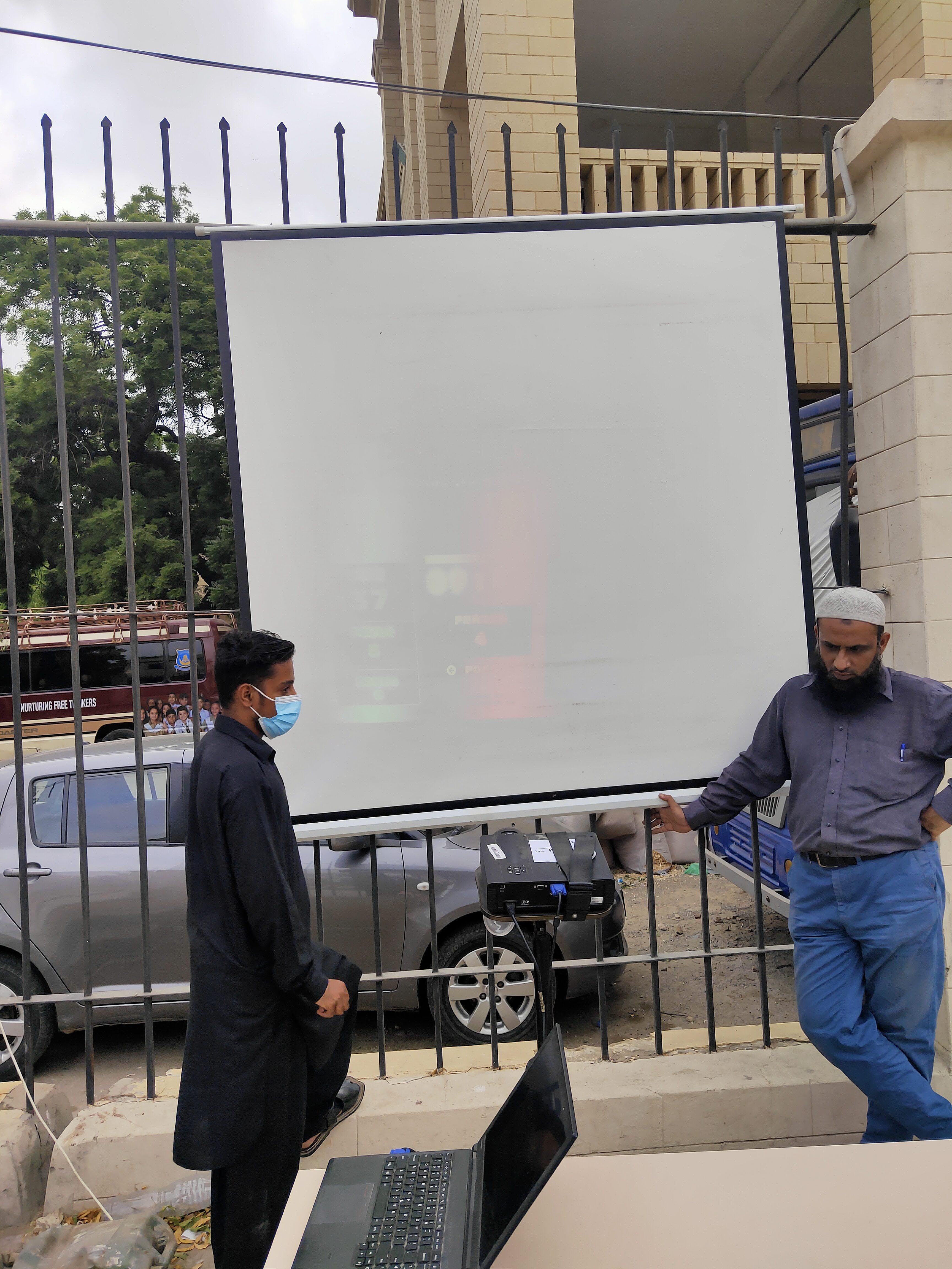
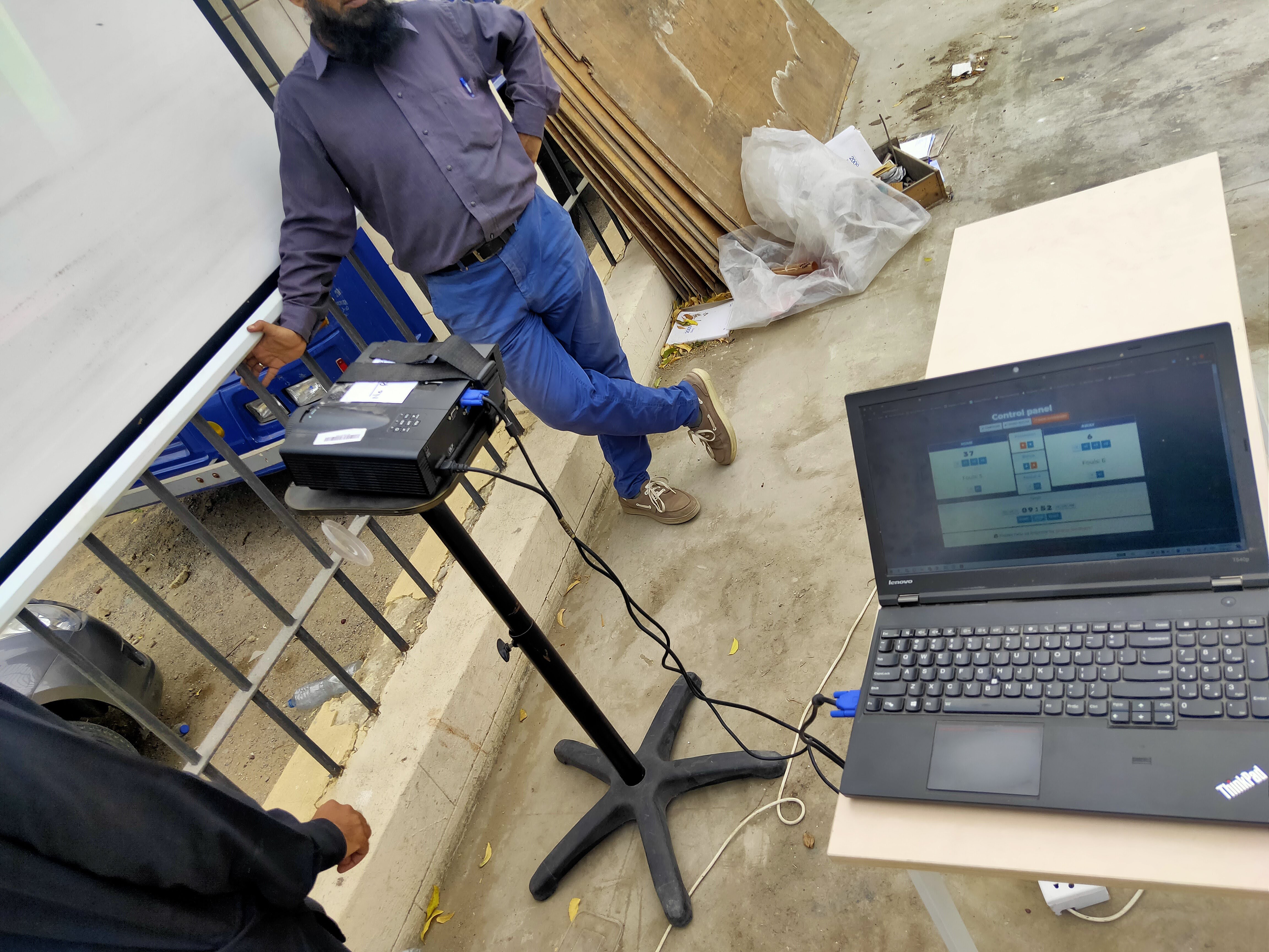
    Initially, we tried our level best to NOT do any work and just use a Laptop and a Projector to make the scoreboard - unfortunately the sun is too bright and we cant do anything about it - this plan failed.

    We tried to use the scoreboard available at the website https://keepthescore.co/

View all 5 project logs

  • 1
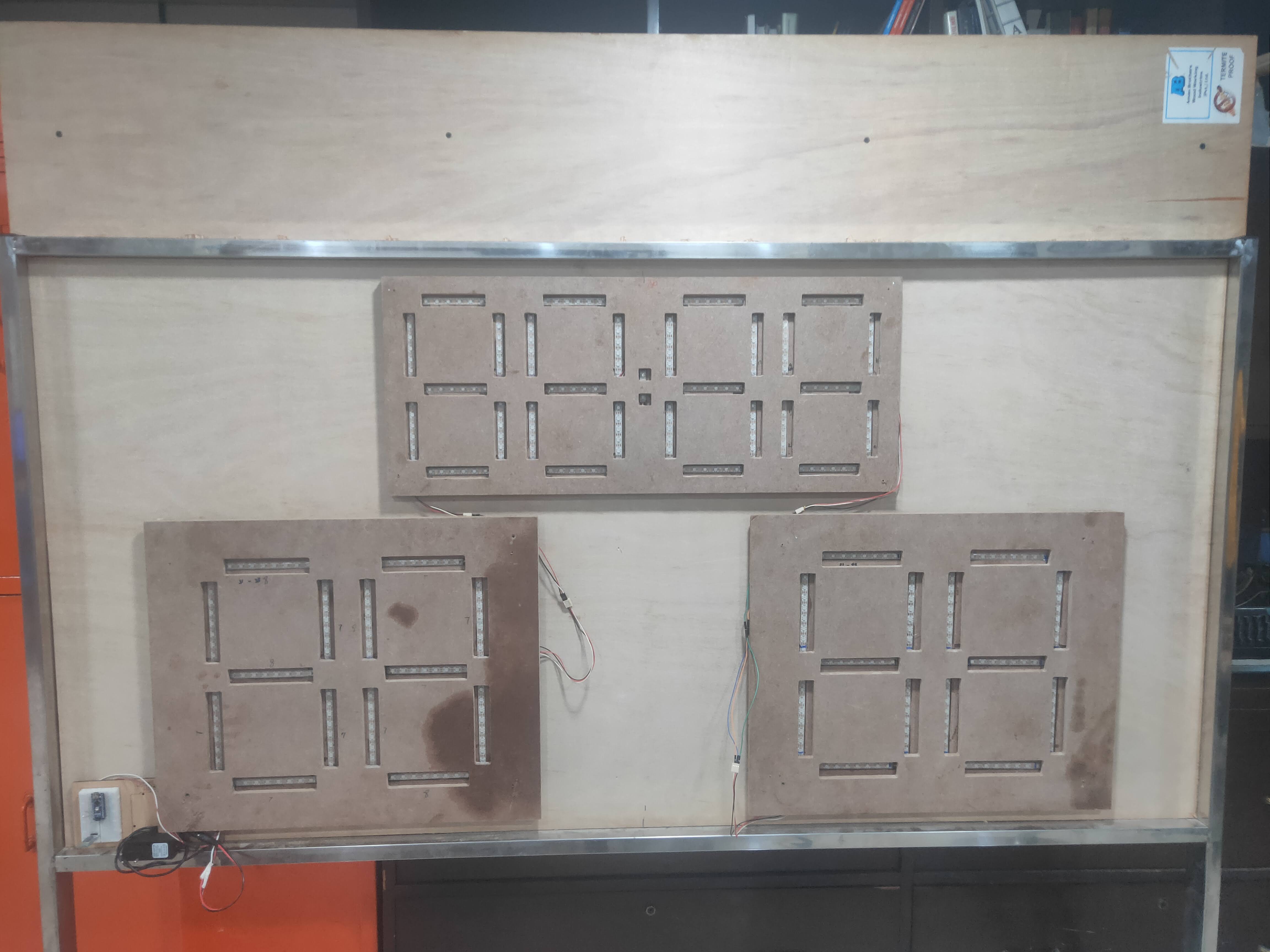
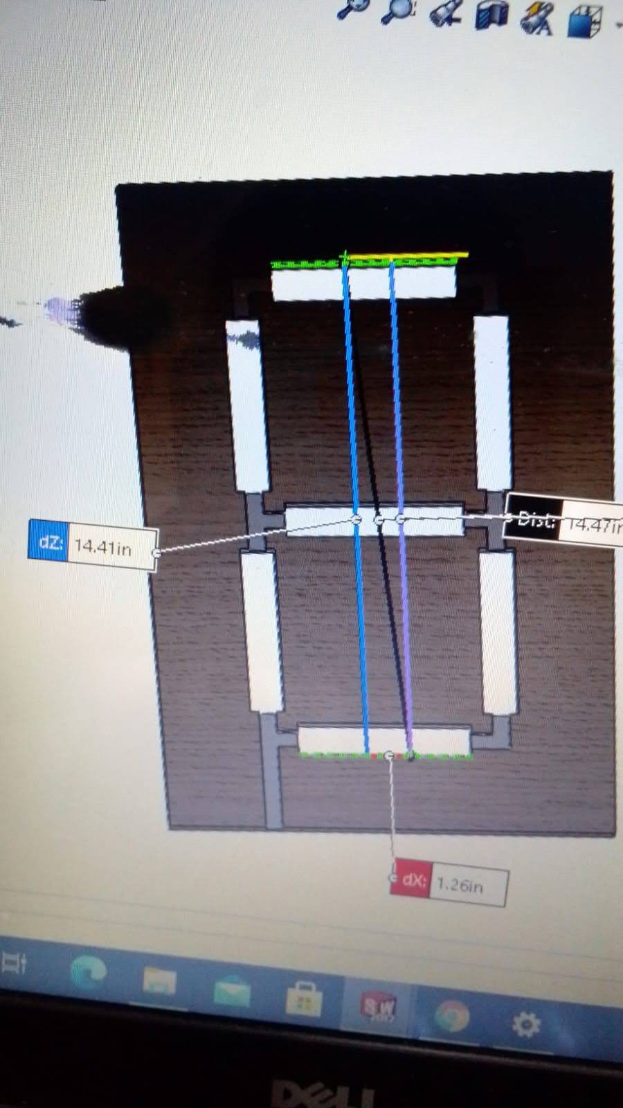
    Determine SIZE and Number of DIGITS Needed and create CAD

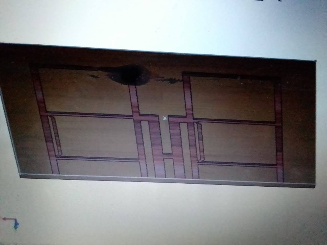
    Create CAD file as per your size and number of digits, it is a good idea to create separate CAD files for different sets of digits, to keep it easy and allows for later change of design as per need.

    We created 3 different sets of digits

    • 2 sets of 2 LARGE DIGITS for showing SCORE
    • 1 set of 4 digits with a COLUN after 2 digits to make TIME, these were slightly smaller

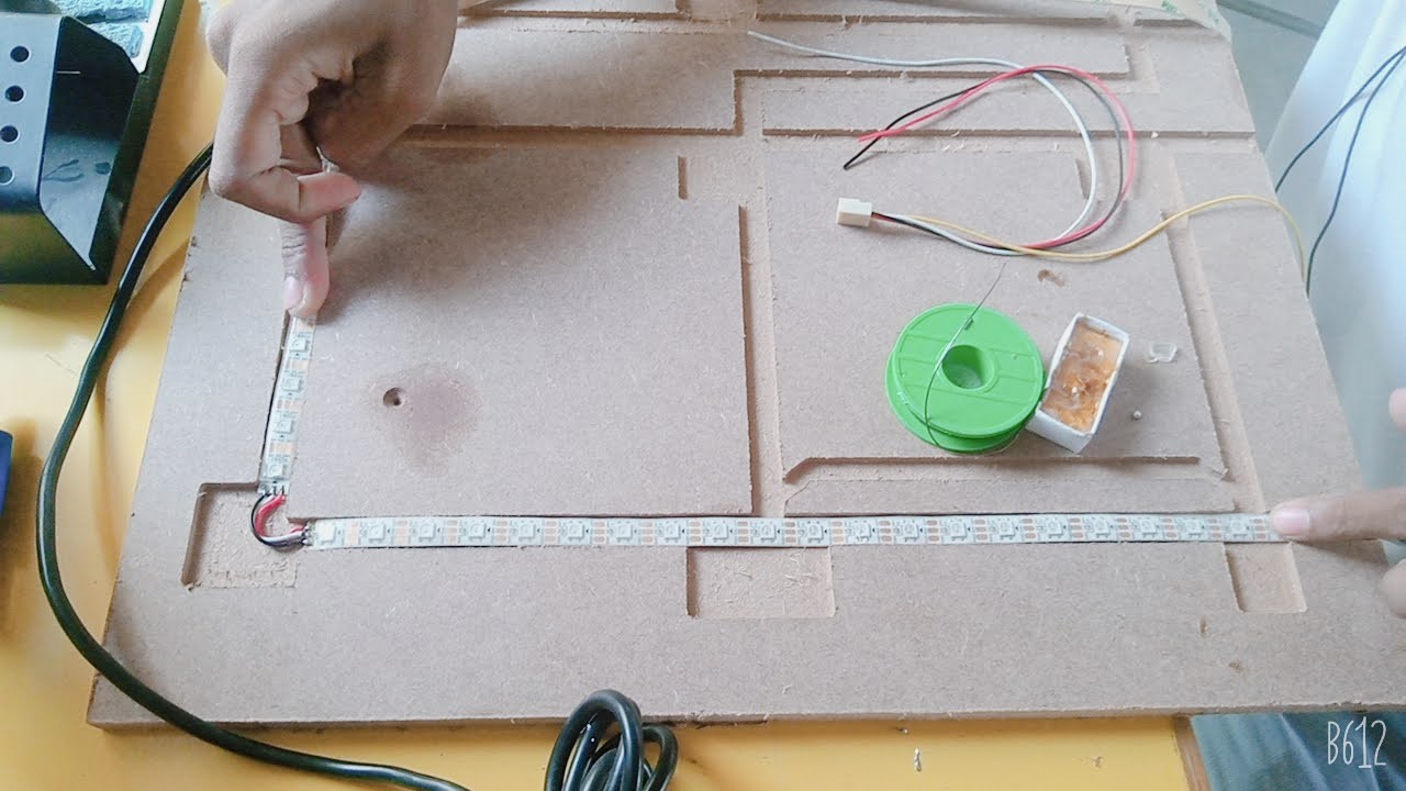
    in the CAD file for MILLING, make sure to keep separate space for WIRES

    There are 2 CAD Files, one for the bottom panel, where the strips and wires are placed and another for the TOP which has the final digit holes milled

  • 2
    Wiring and Noting the LED Numbers

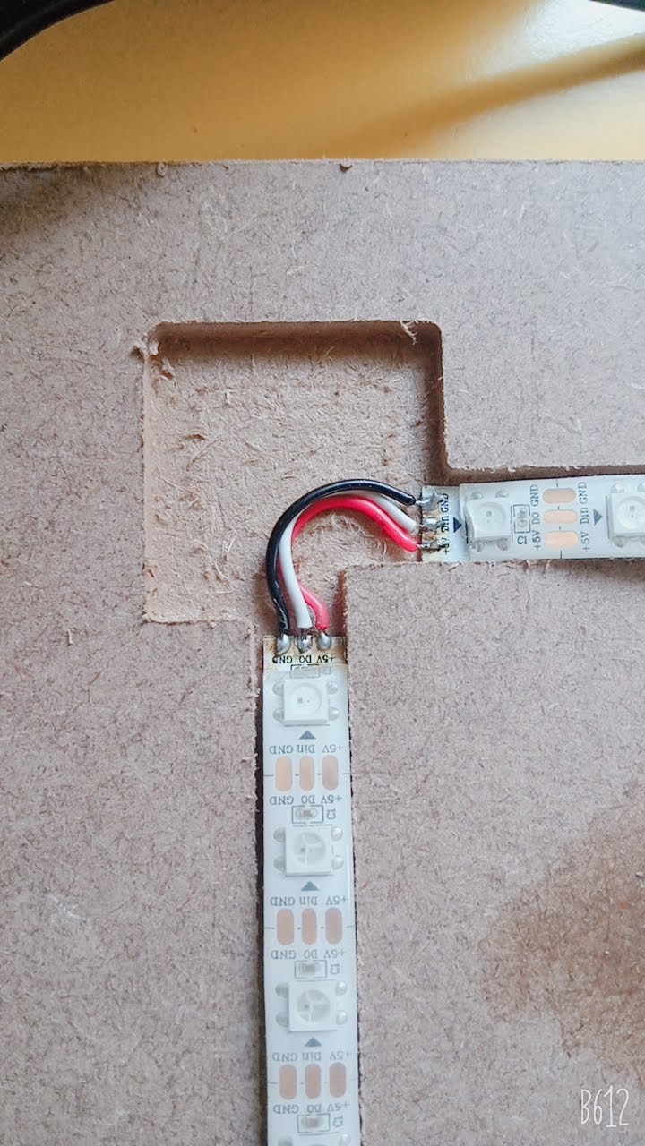
    Wire the LEDs properly, make sure to have separate POWER lines 5V and GND for each segment set so to later connect to power supply, 1 single line to power all digits is NOT a goo idea, we tried, the last 3 digits were not BRIGHT enough on the power supply.

    While wiring, we did not follow the seven segment ABC order but created our own, as per the image, this allowed for ease in wiring.

    Later, we counted the LED numbers for each segment on a paper and then coded that in the program.

  • 3
    Use a BEEFY Power Supply

    We were using a Small Wall Power Adapter, 5V, 3A, but I think the sticker was a lie and it was NOT able to provide 5V and 3A

    We ultimately changed that to an old PC Power Supply. and connected the 5V and GND of each set of our 2 and 4 digit displays separately to different POWER lines coming from the power supply.

    Remember to attach a SWITCH to the GREEN and BLACK wire on the 20/24 pin cable of the PC Power Supply to give it an ON and OFF signal

View all 4 instructions

Enjoy this project?

Share

Discussions

Jeremy234 wrote 03/16/2023 at 07:14 point

I remember my dad. He's an electrician and he helped me on my scoreboard in my middle school days.

  Are you sure? yes | no

didan92426 wrote 03/15/2023 at 02:31 point

I am trying to make a small portable version with 288 leds. (600x520mm) I try to include "fouls" and "period". Forgot to say that it's for my neighbours son's team, but that's even more satisfying if it works.... Have to make it in my freetime, so will take a while. Will definately show the results when finished!! Thanks again. https://locksmith365nv.com/

  Are you sure? yes | no

mnaveedhaq wrote 02/19/2022 at 12:45 point

Dear Zaid,

Really like your project. We are trying to build scorecard for cricket in Germany. However I would like to know more about circuit diagram. Would it be possible to share it. Actually I am interested to know which value of Resistance and Capacitance did you use.

Secondly by reading the code I understand that you are using one Arduino PIN for all the modules. Why not using different PINs for different modules (scores)?

Regards,

Naveed

  Are you sure? yes | no

ZaidPirwani wrote 04/07/2022 at 06:12 point

I am not sure what you mean by resistor/capacitor - I am using NeoPixel Strips, they ahve the resistor/capacitors all builtin
The beauty of neoPixel strips is that you dont need to use multiple pins, 1 pin can control many.
Also, I think initializing multiple neoPixel objects would be heavy on code/ram

The schematic is simple and mentioned in the code itself, 1 pin from arduino to nepixel, 2 pins for bluetooth serial 

  Are you sure? yes | no

Fred wrote 10/30/2021 at 18:08 point

I am trying to make a small portable version with 288 leds. (600x520mm) I try to include "fouls" and "period". Forgot to say that it's for my neighbours son's team, but that's even more satisfying if it works....

Have to make it in my freetime, so will take a while. Will definately show the results when finished!! Thanks again.

  Are you sure? yes | no

Fred wrote 10/24/2021 at 13:22 point

Really nice work! Trying to make this work for my neighbours basketball-team. Just get stuck at adding bluetooth into the code. Would it be possible to give acces to your fully working code? I can get my HC-06 working with simple code, but don't know how to incorporate it in yours... can you help me?

  Are you sure? yes | no

ZaidPirwani wrote 10/24/2021 at 16:20 point

all the final code is available
https://cdn.hackaday.io/files/1817577776291488/scoreboardV3.ino

Please have a look at the files and Build Instructions.

Also, the code works with the SERIAL TERMINAL APP in Android.

This app has buttons which you can SET to send fix macro strings

I set strings like
L3 - Capital L and 3 add 3 to LEFT, small L (l3) would decrease the score.

Similar for TIMER, T1 to start and stop timer
M for Minutes and S for seconds.

  Are you sure? yes | no

Fred wrote 10/24/2021 at 17:06 point

thank you so much! Made a big error with TX and RX pins (have a Mega here). Works great! Again, really great work!

  Are you sure? yes | no

ZaidPirwani wrote 10/25/2021 at 17:13 point

would love to see your build and see how it is different.
Also, as I am in a school, it would be cool to show my students something form the other side of the world and importance of online sharing and collaboration and project documentation.

  Are you sure? yes | no

Gregory Sanders wrote 09/28/2021 at 11:02 point

Good job!  Feels good to build it yourself.

  Are you sure? yes | no

Similar Projects

Does this project spark your interest?

Become a member to follow this project and never miss any updates