-
1Warm-up: Be ready for soldering!
Please be careful with soldering. Too cold and you will get cold joints with false contacts. Too hot and you could destroy the soldering pad and break connections. Try to use flux to help you. Use the right solder tip, the right iron and the right temperature for your soldering wire.
Here you can find a tutorial for through hole components soldering:
Through hole components soldering tutorial
If you have any performing issue after finishing soldering, check the TROUBLESHOOTING part at the end of the list.
-
2PCB Top
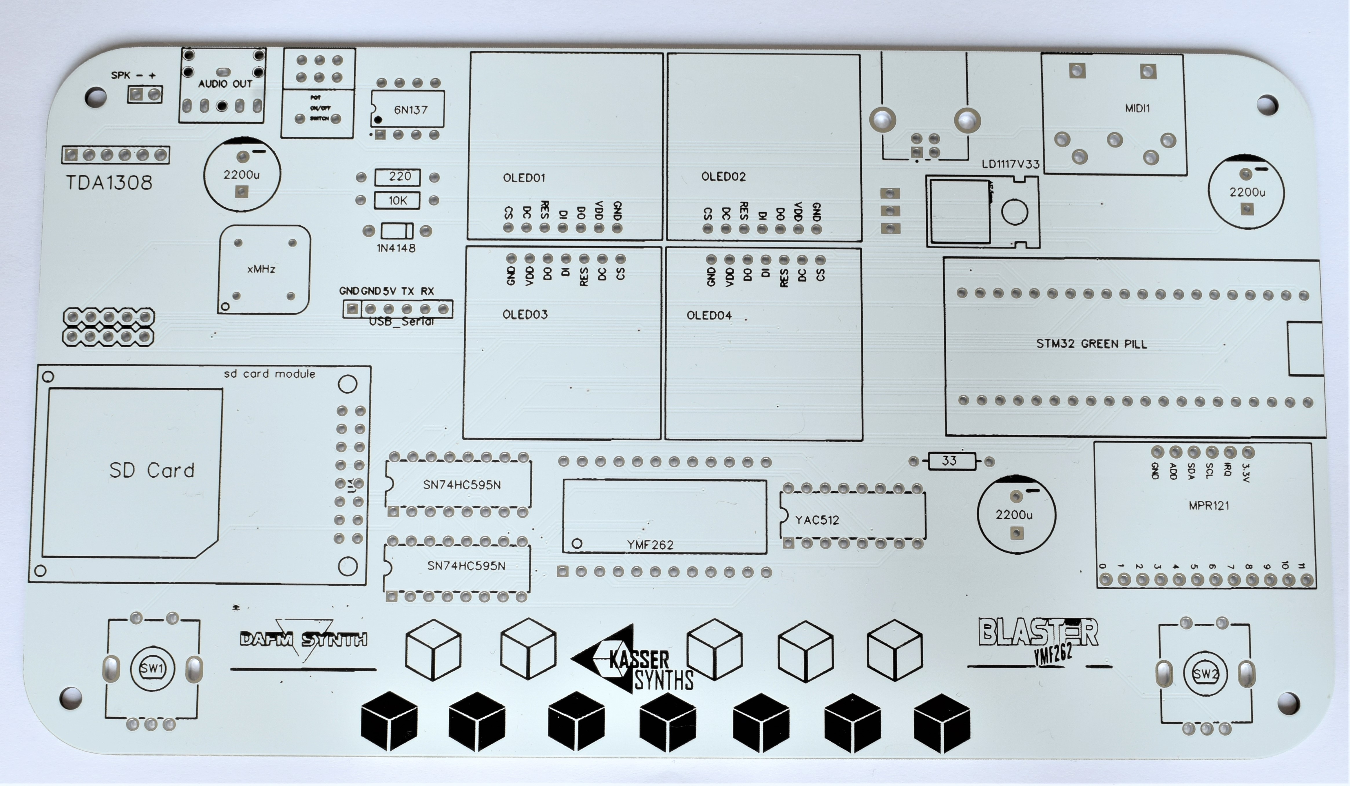
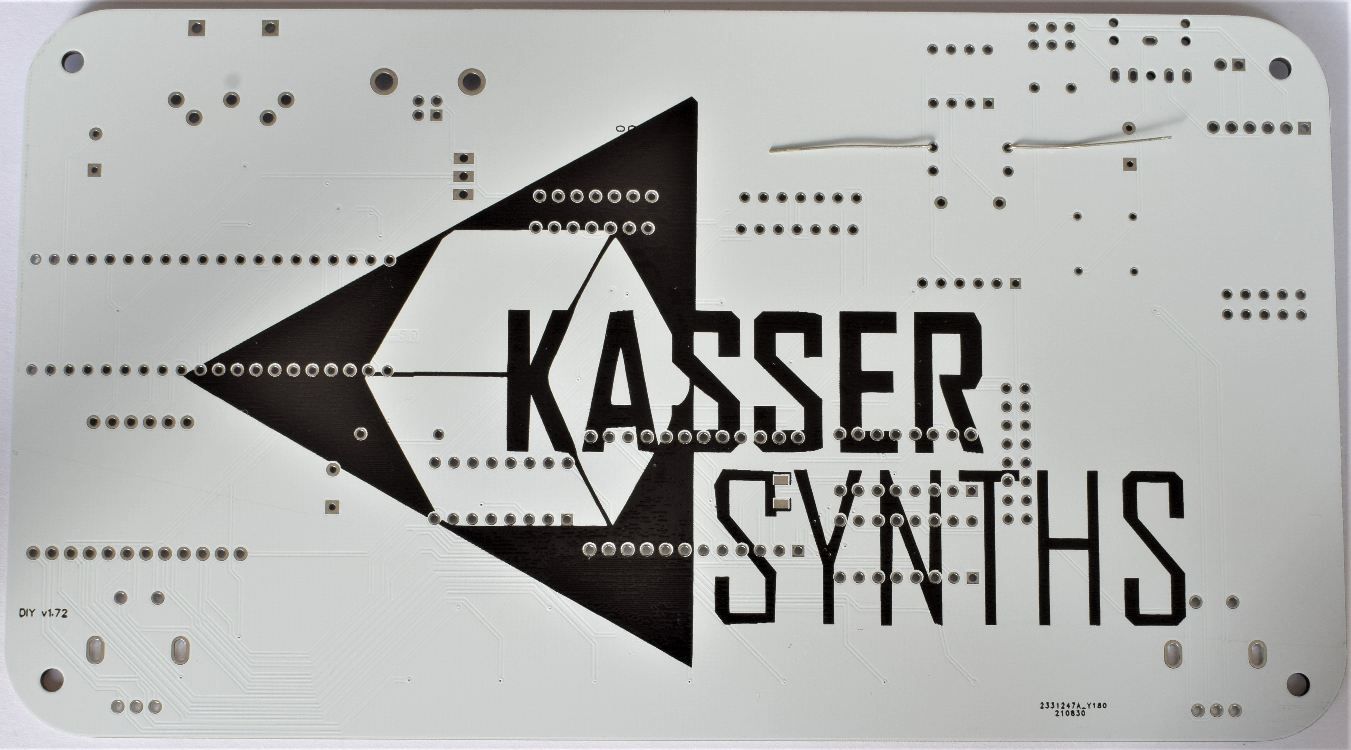
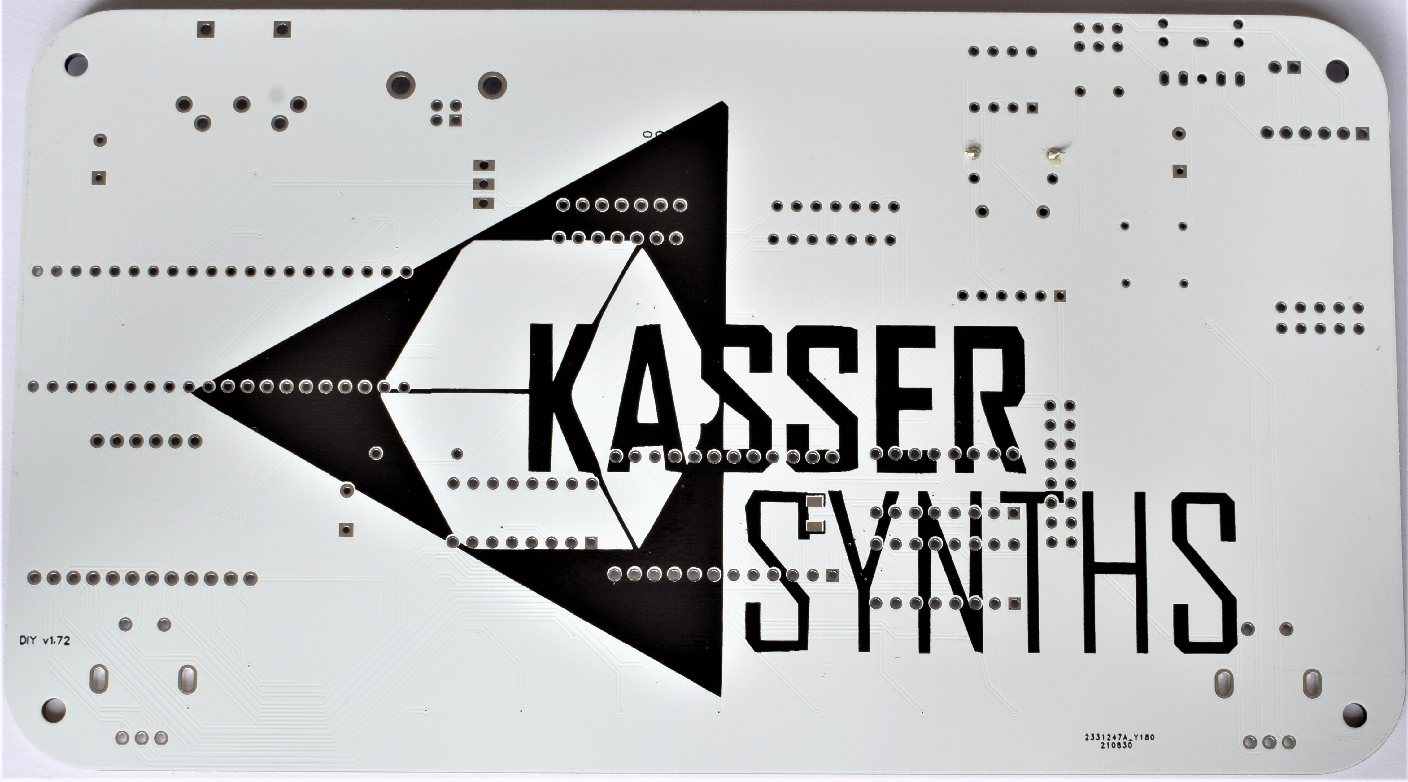
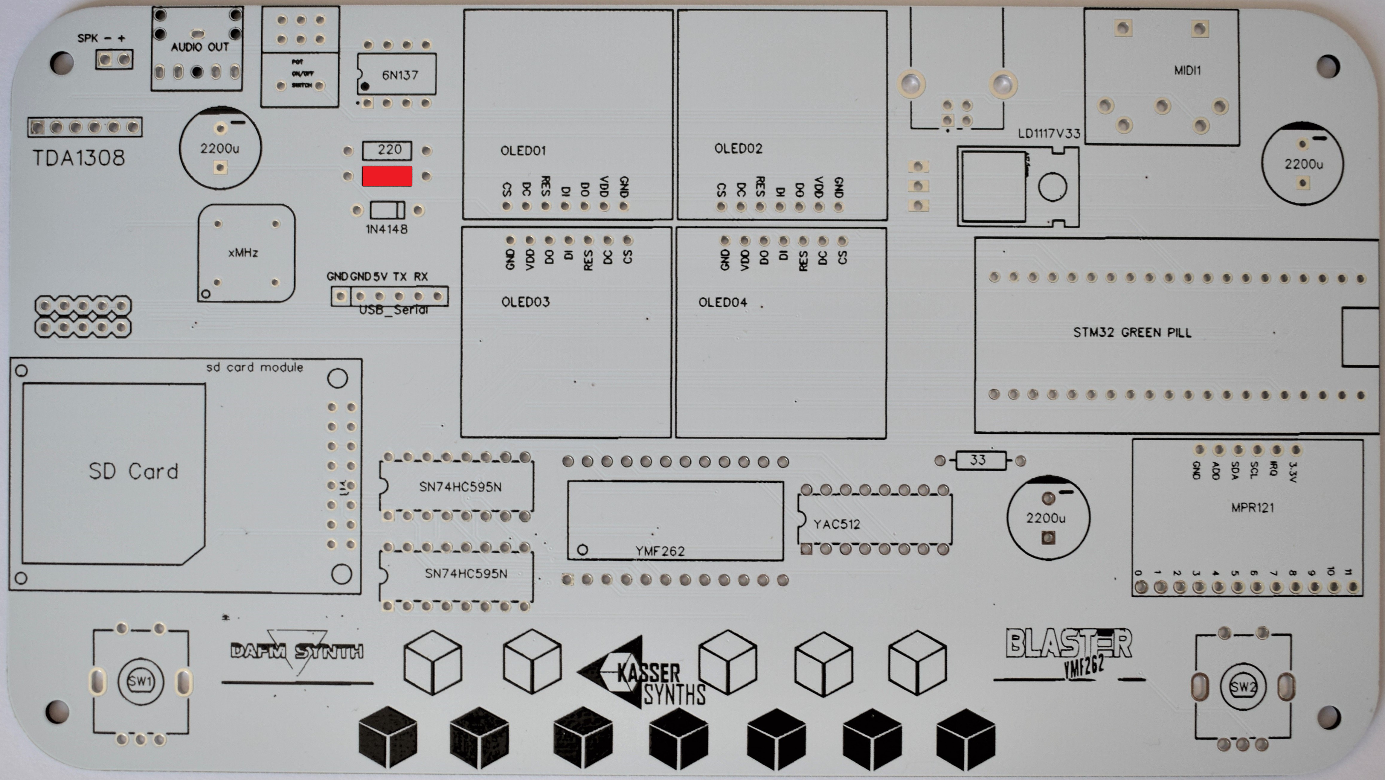
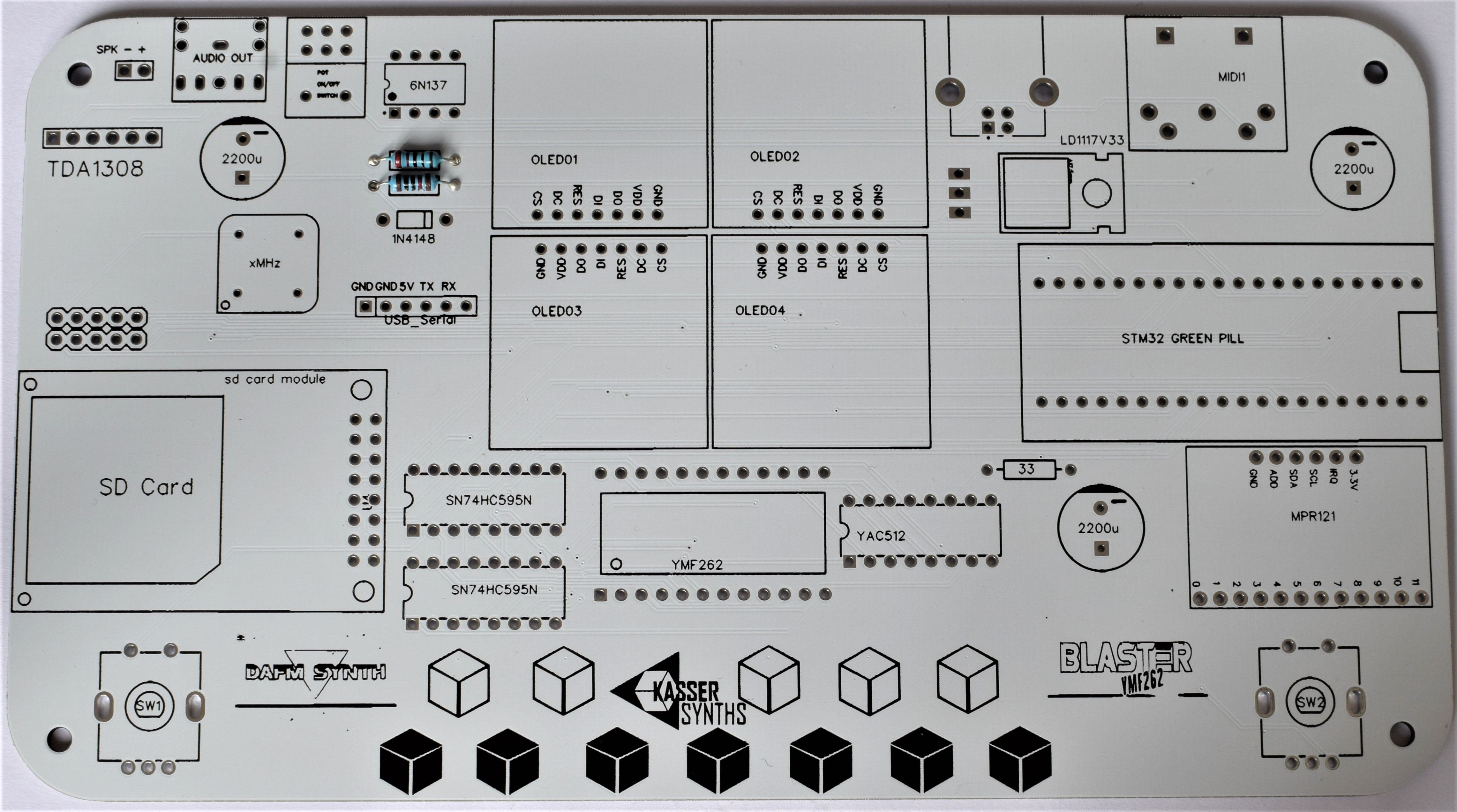
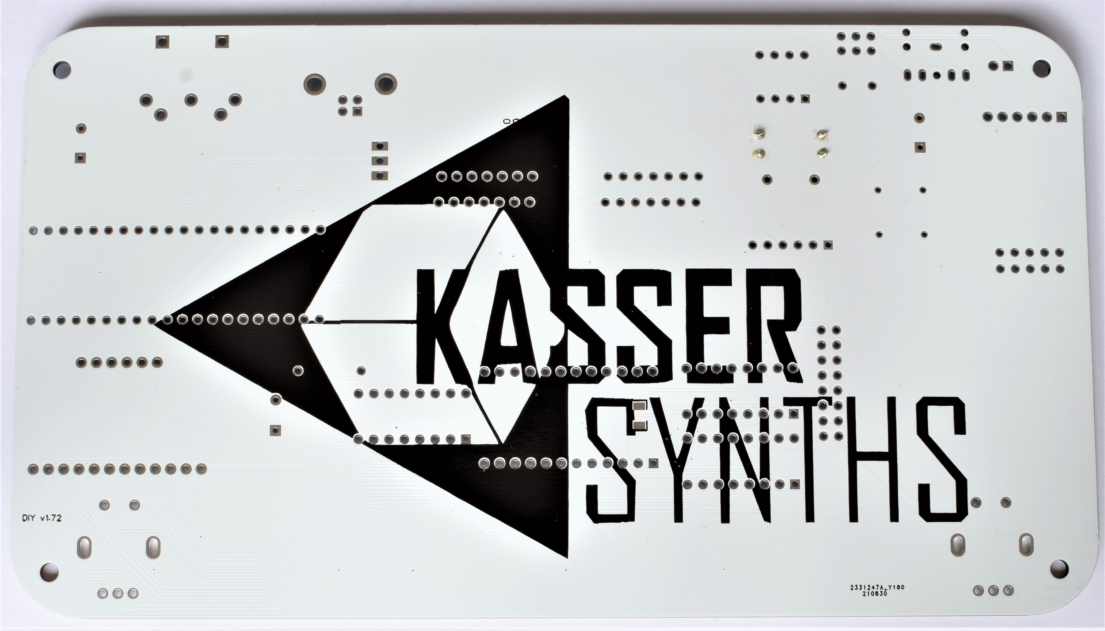
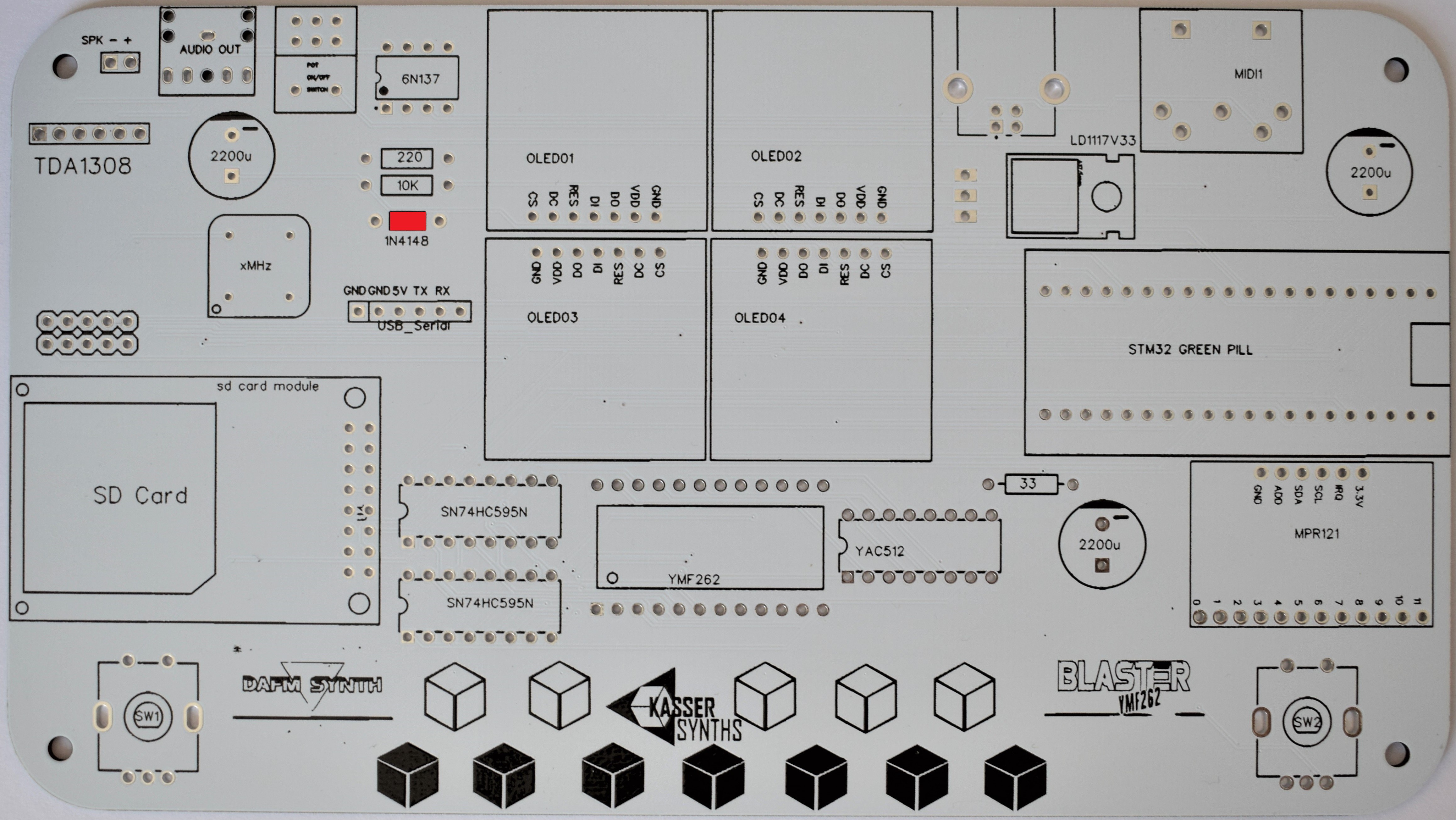
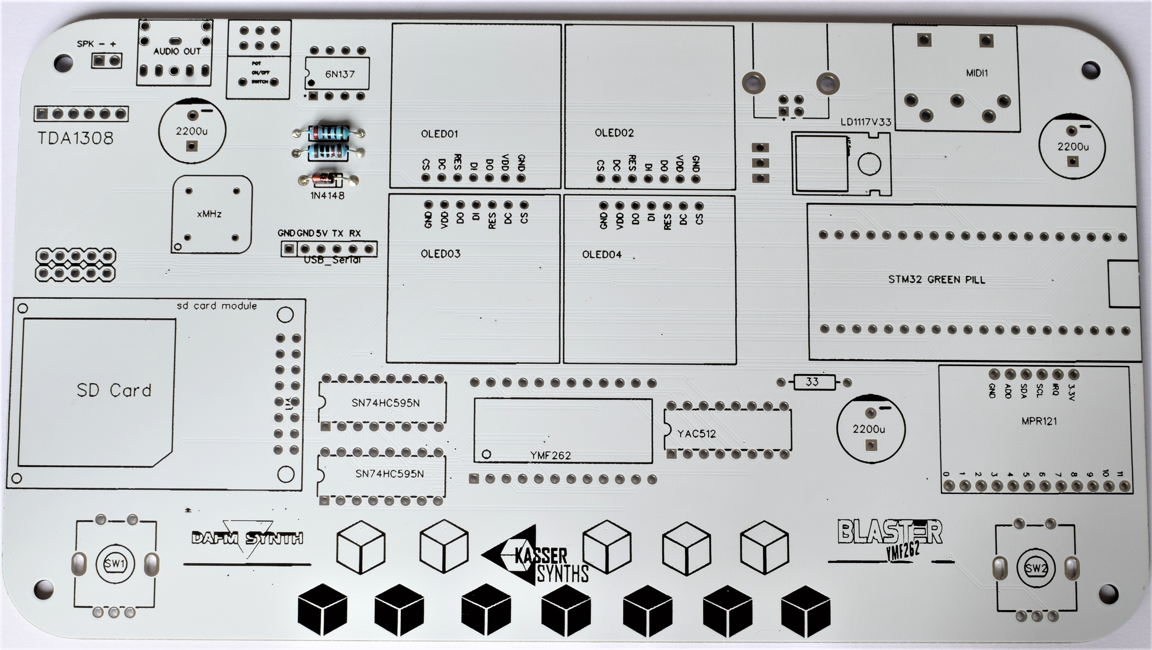
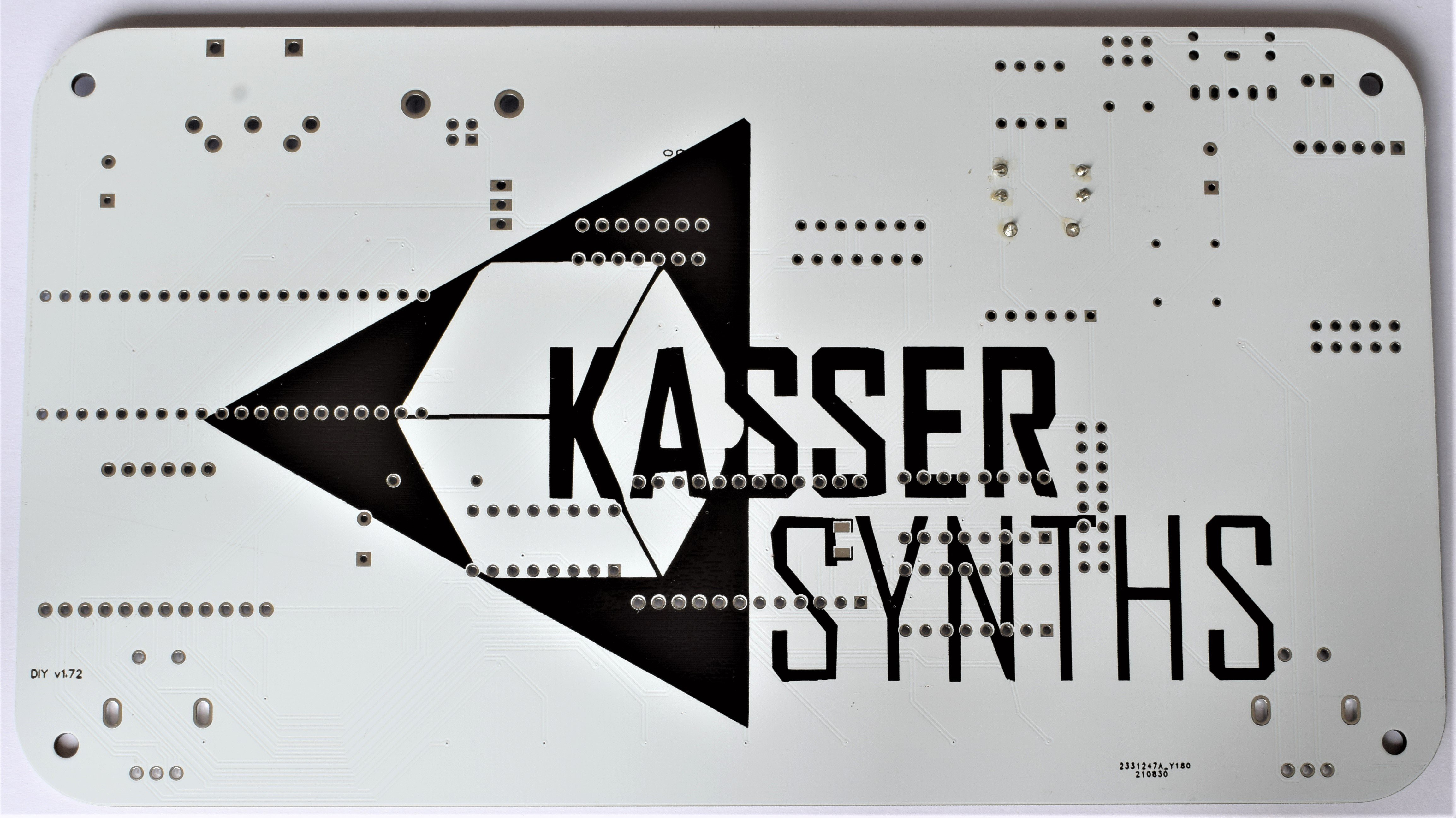
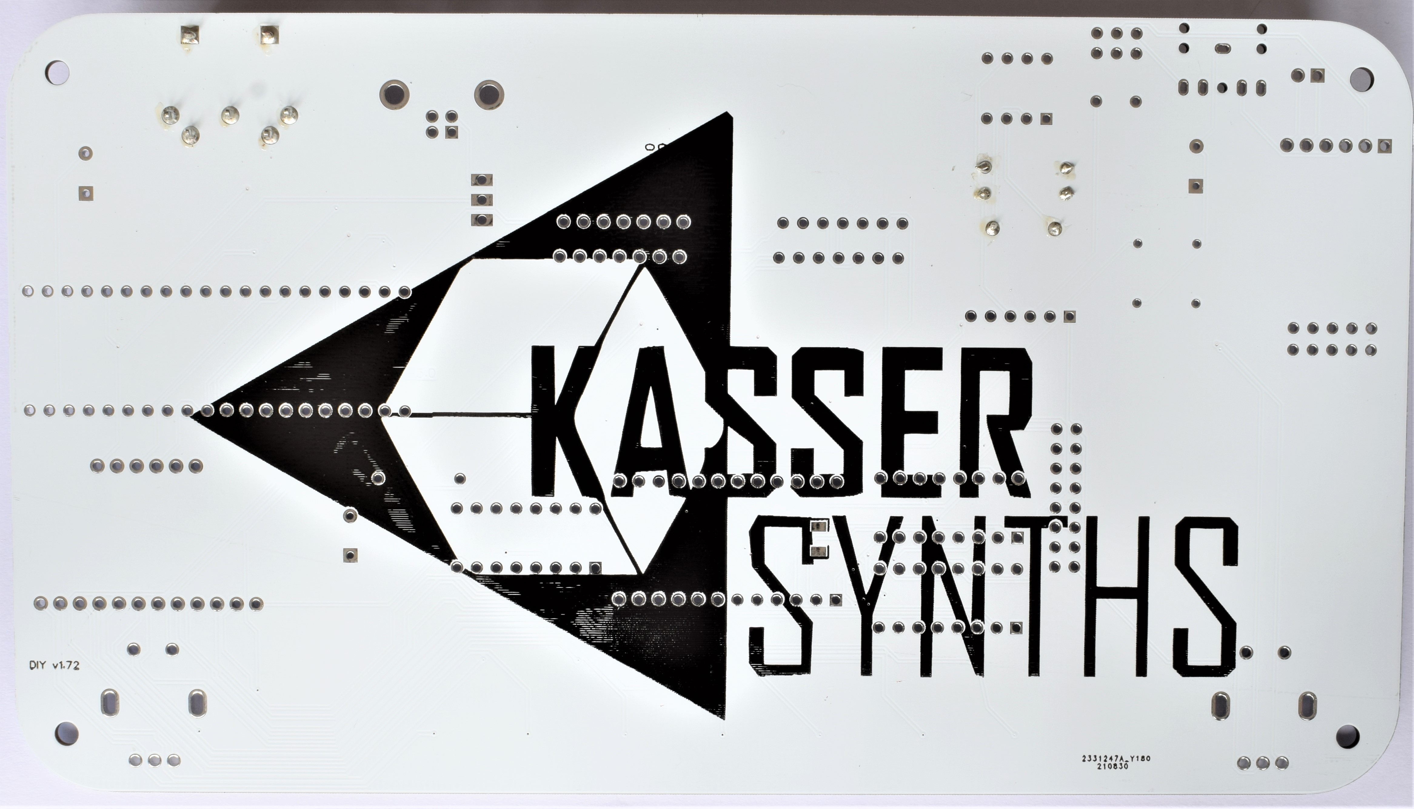
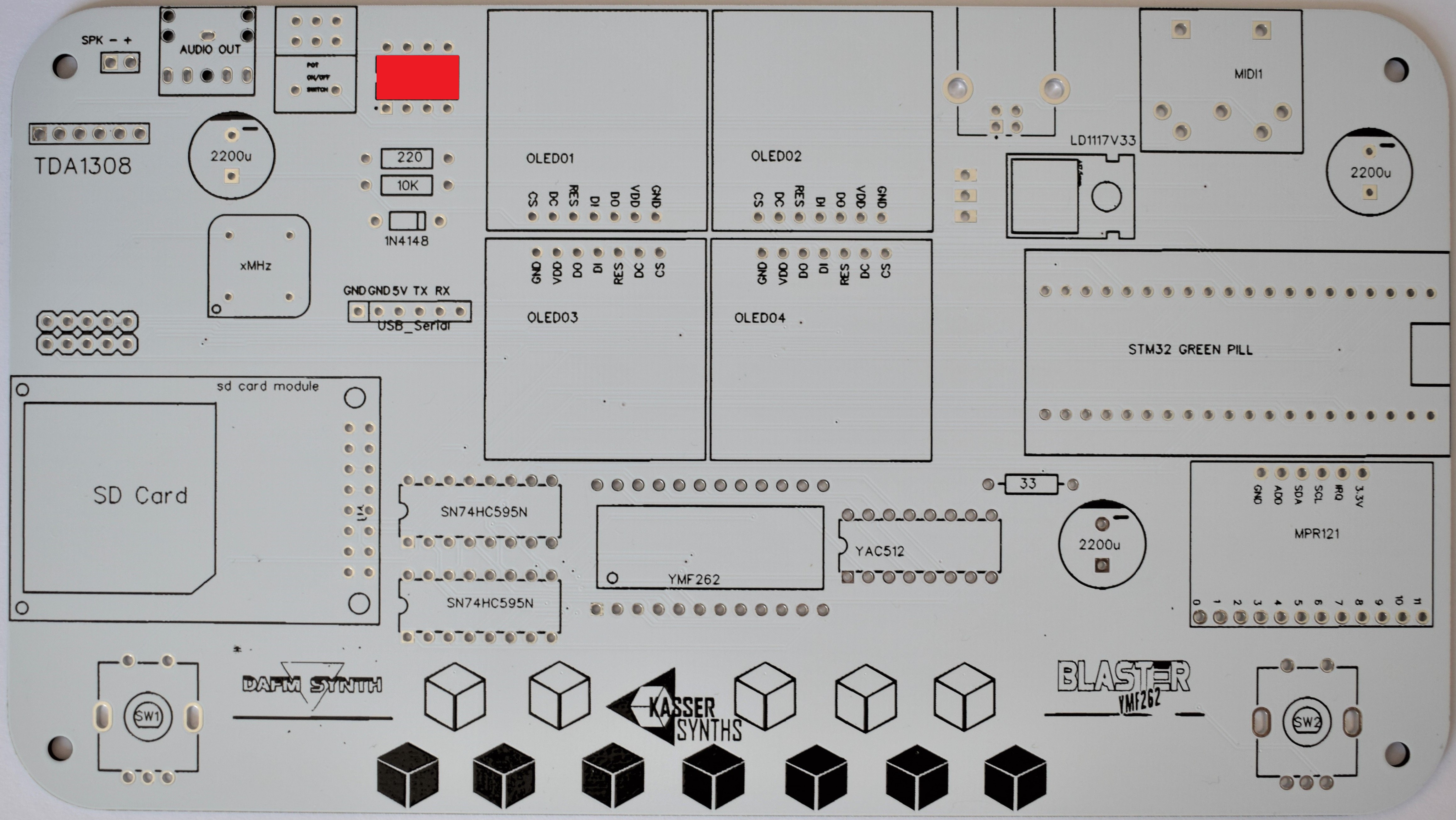
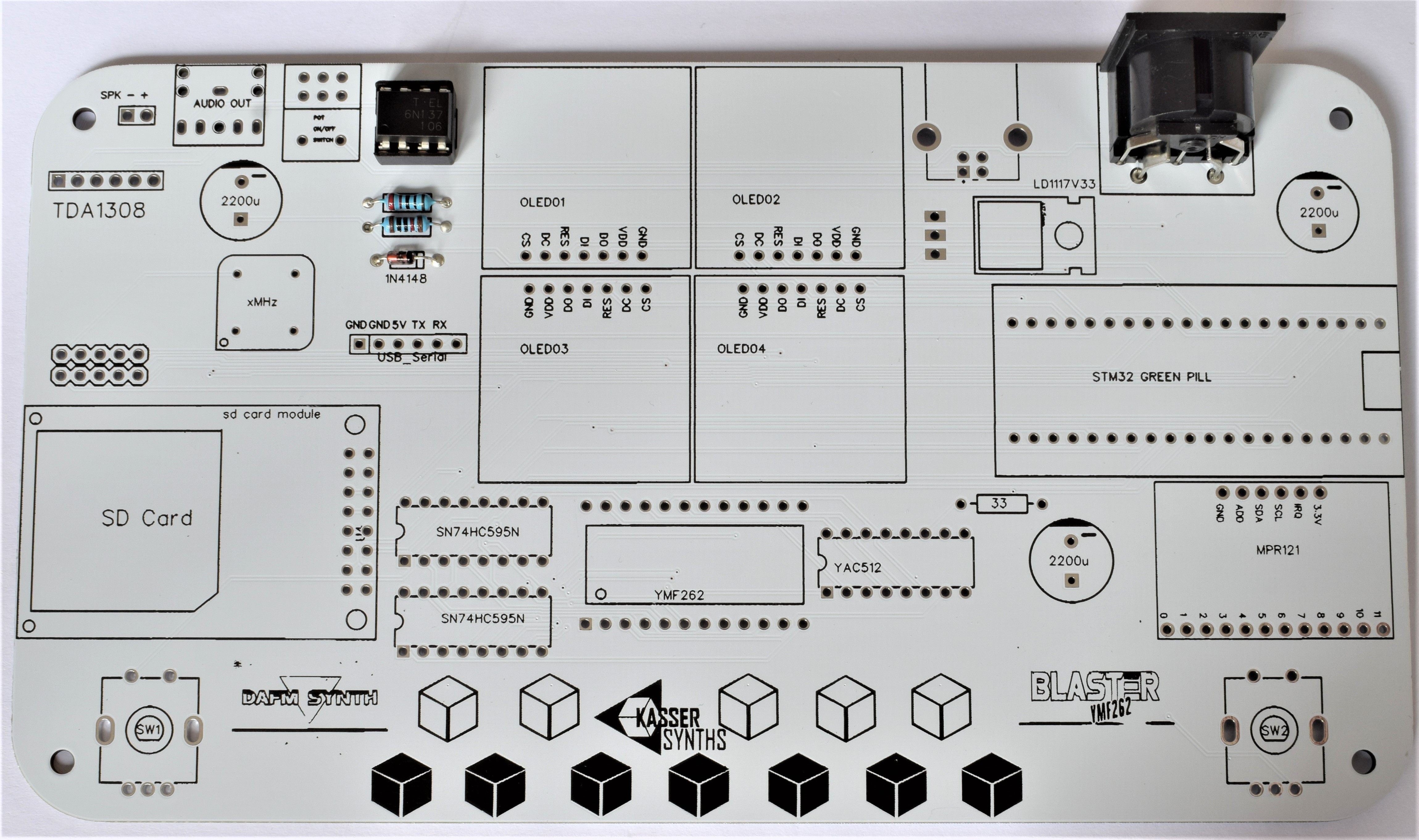
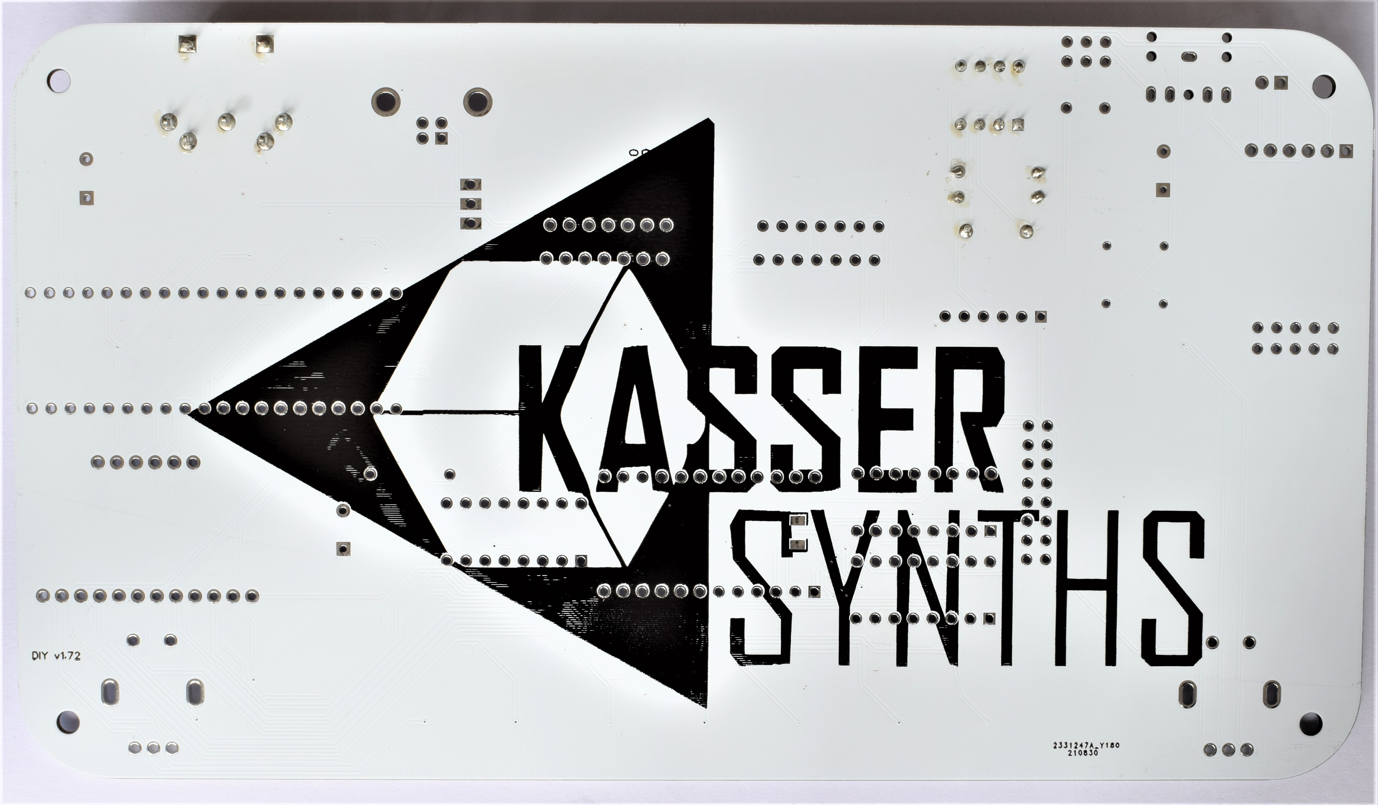
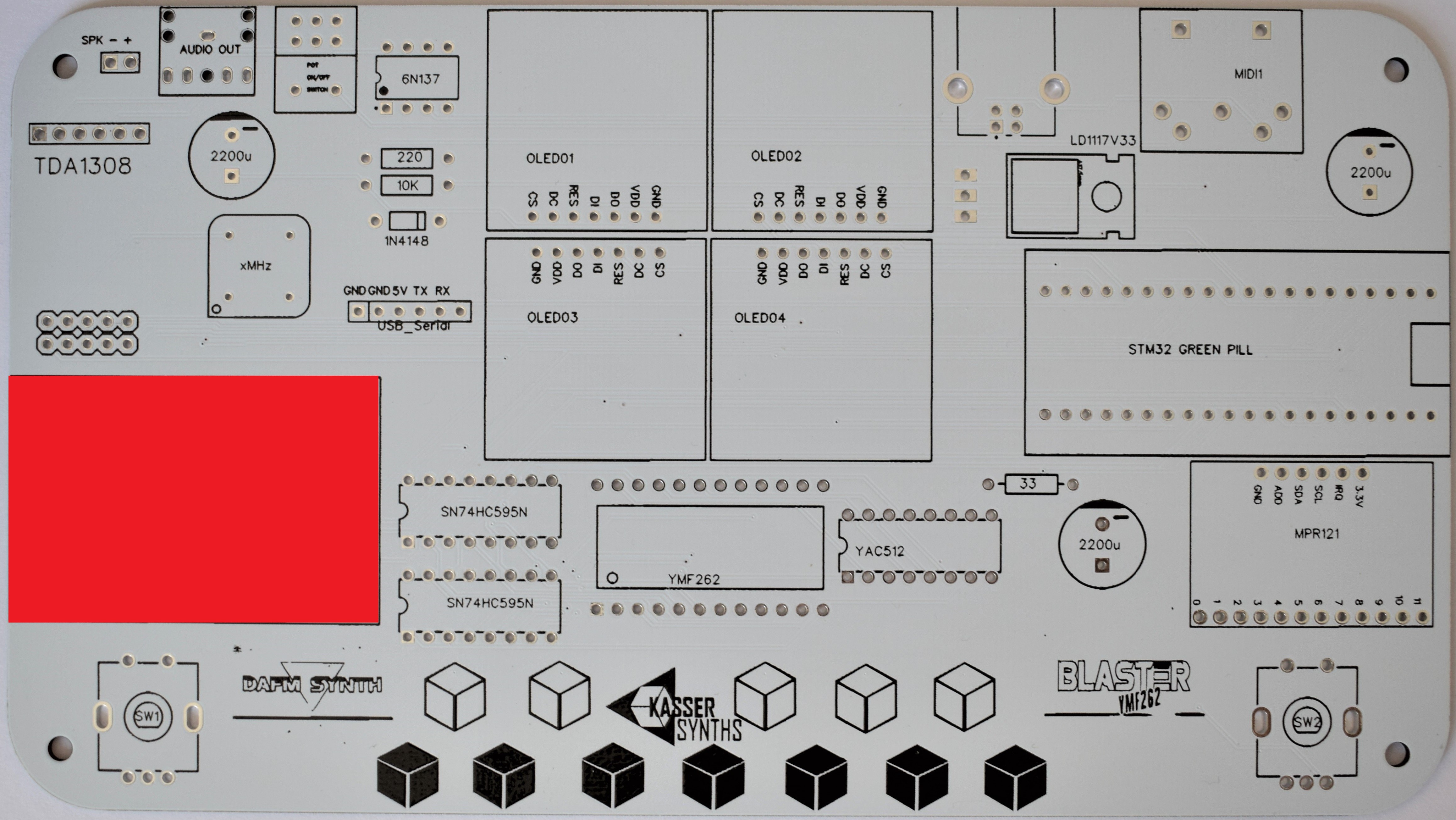
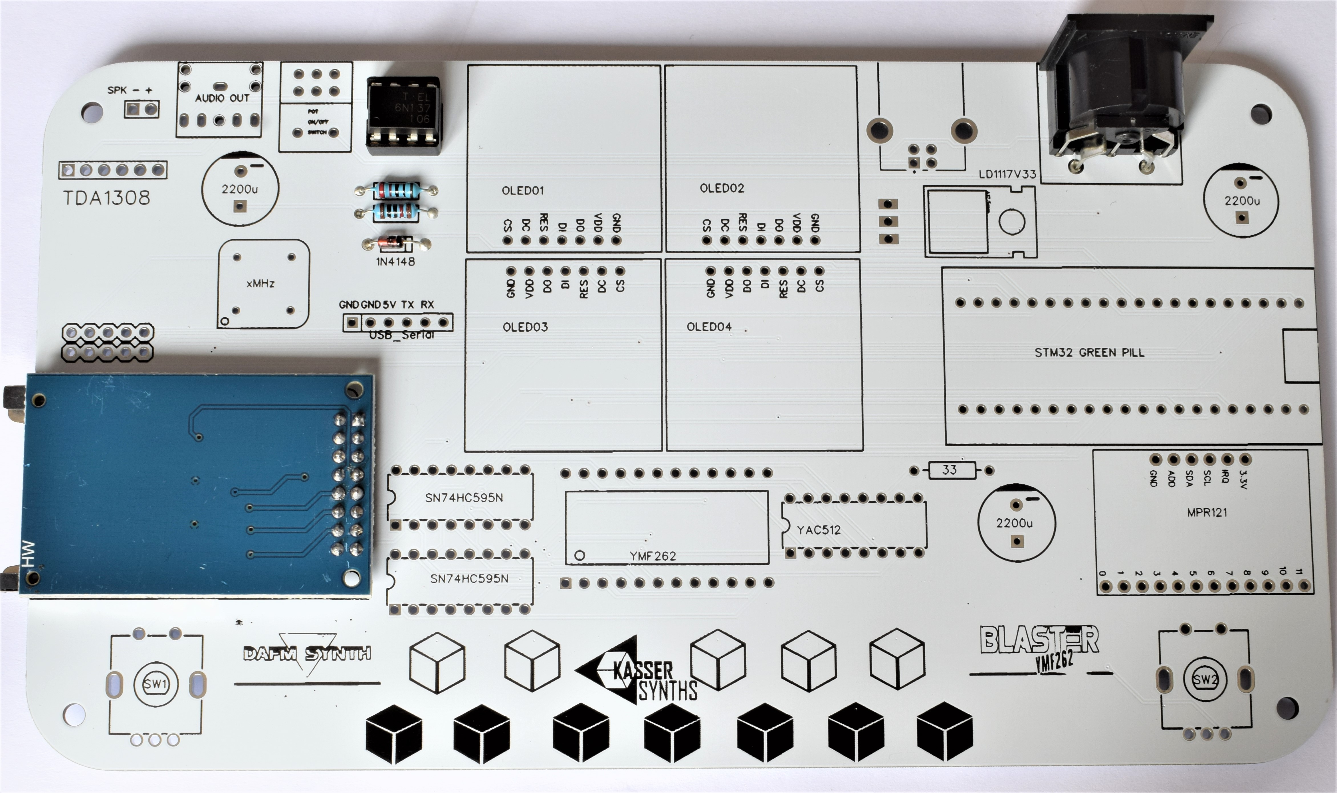
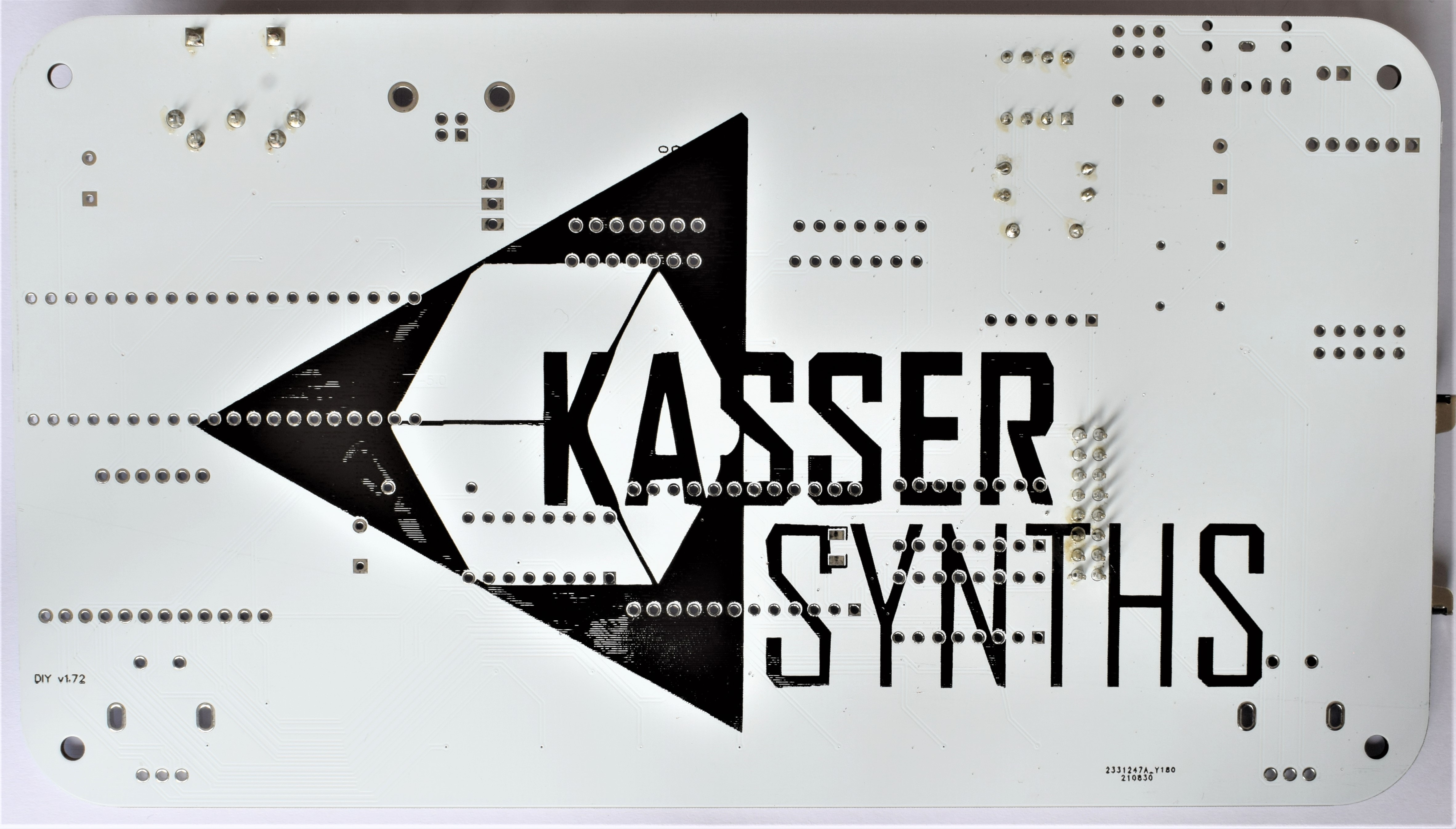
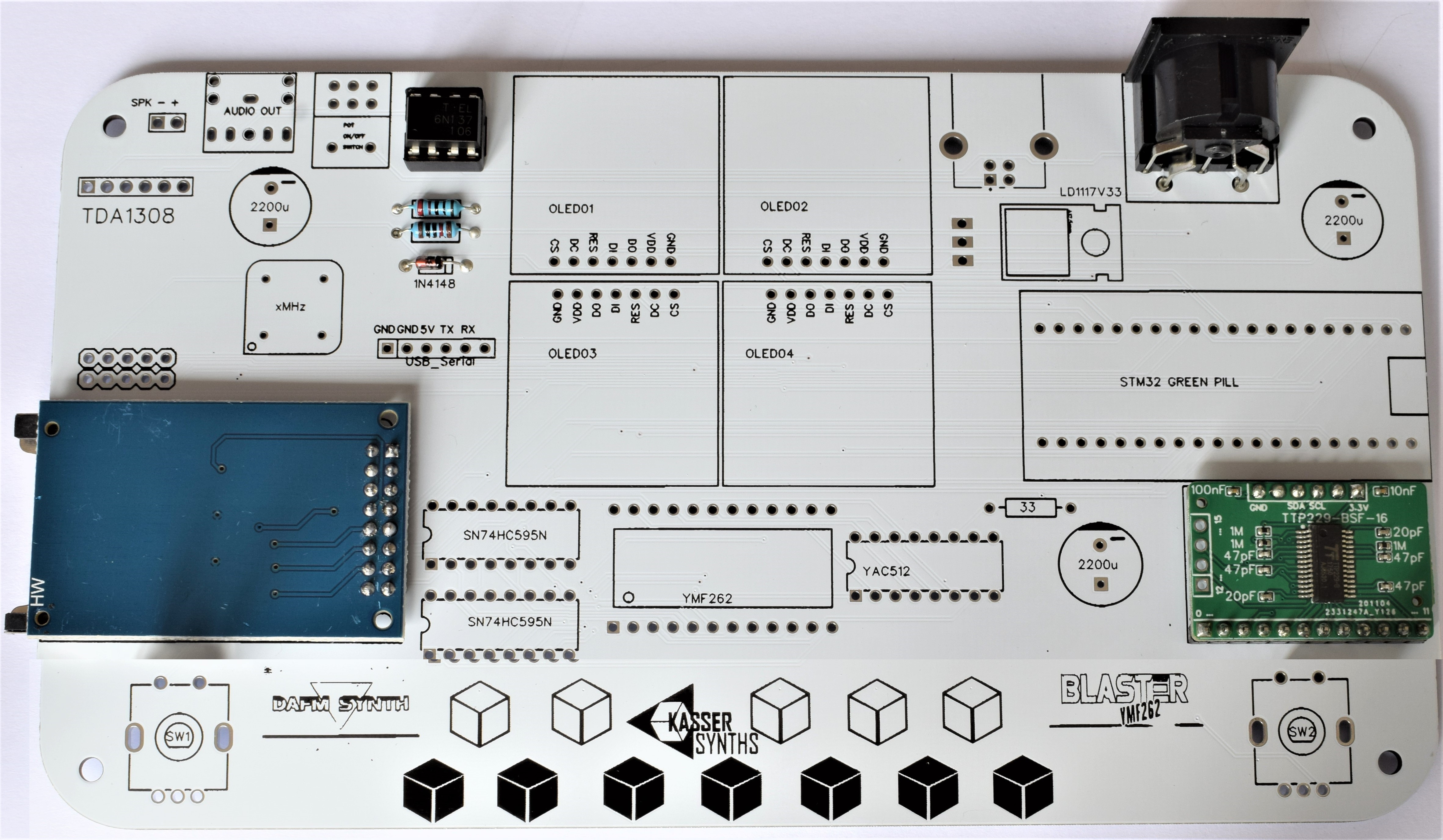
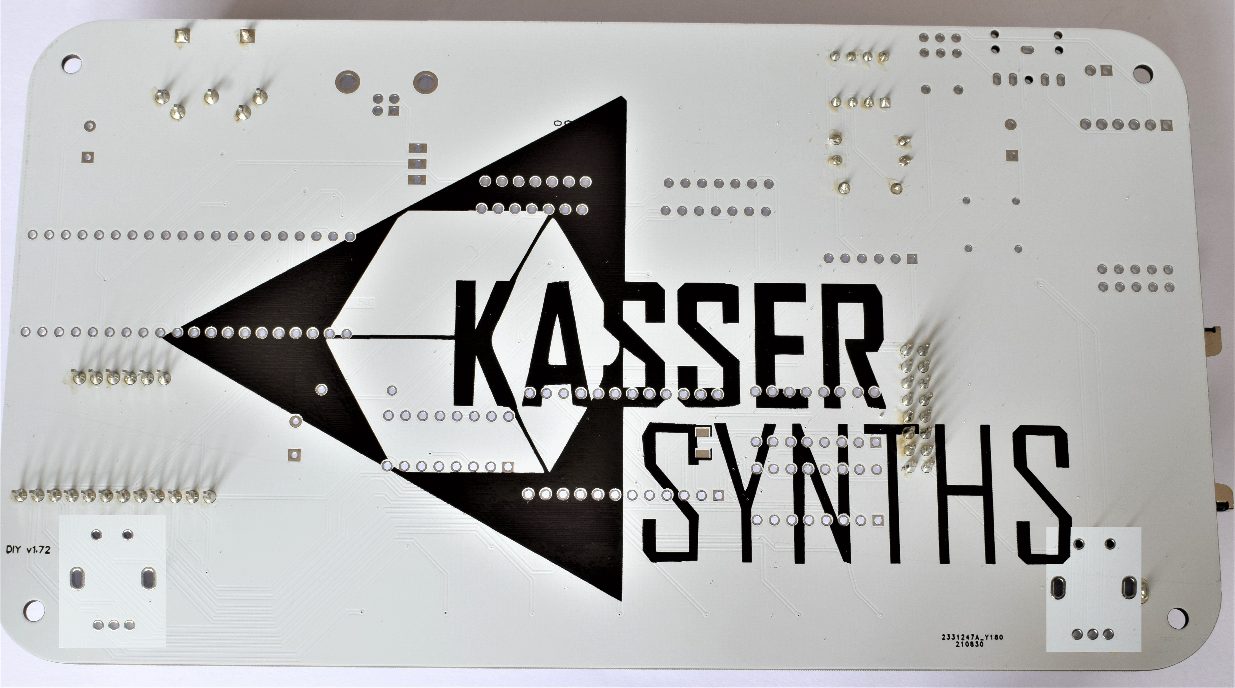
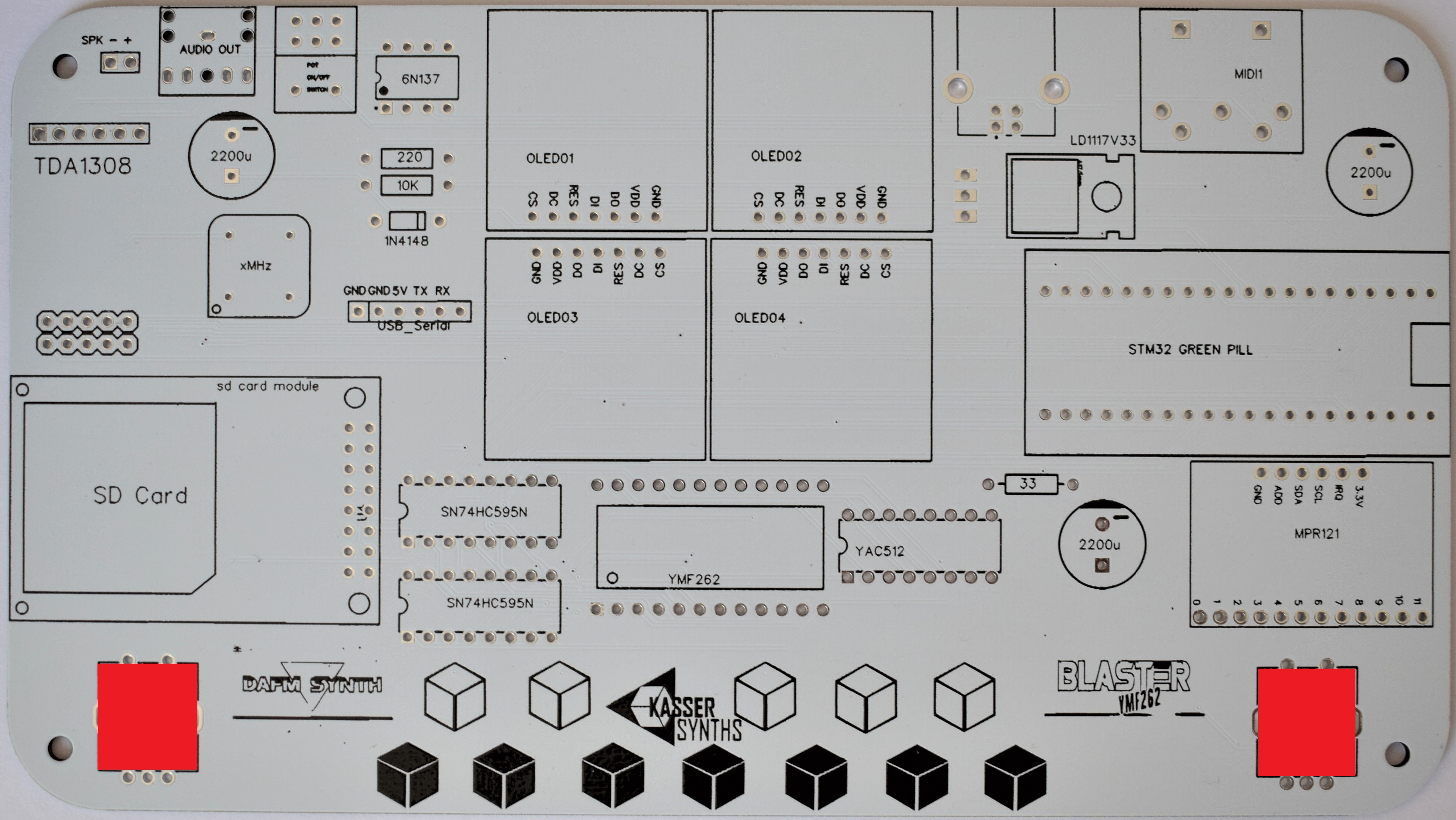
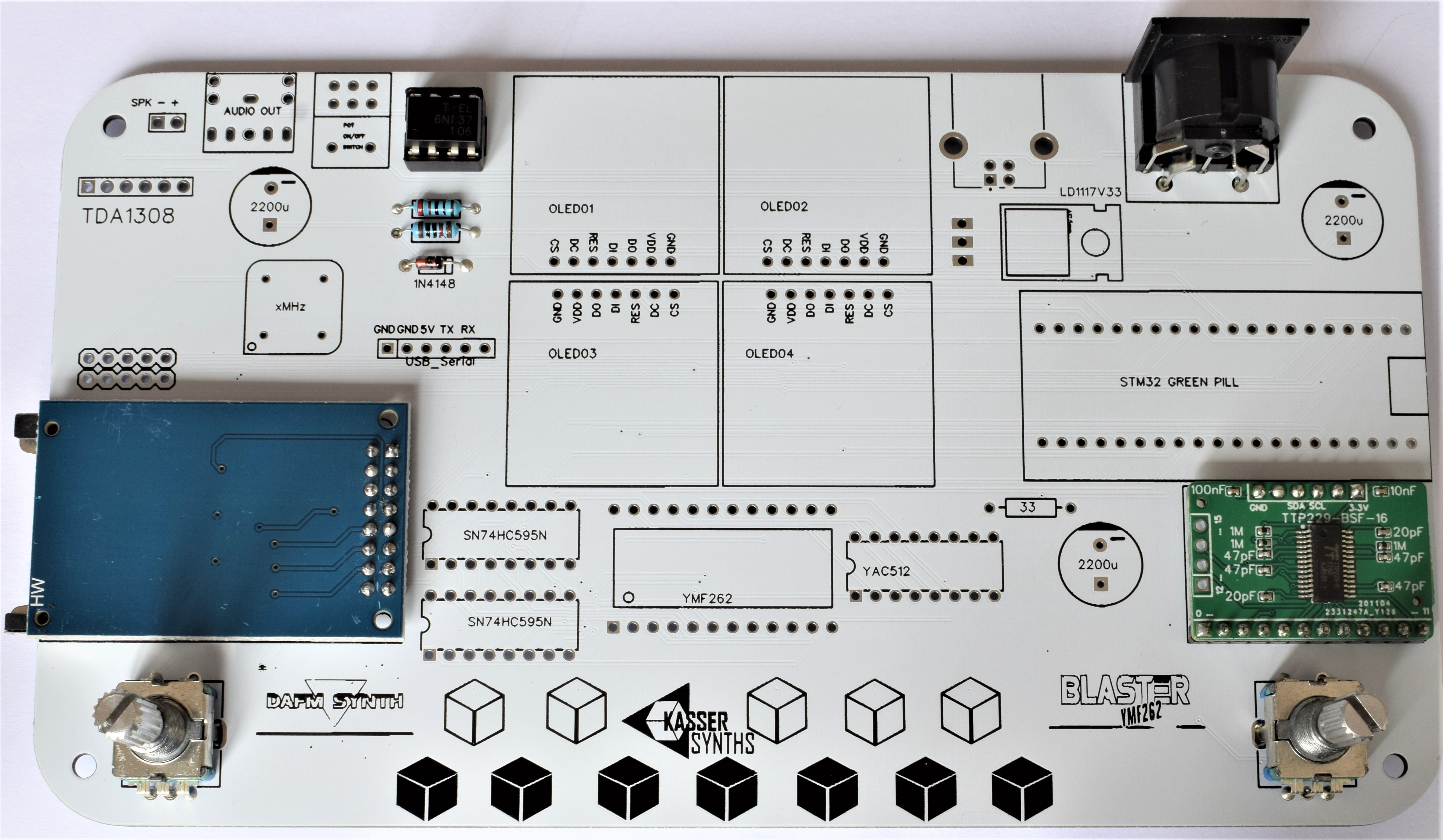
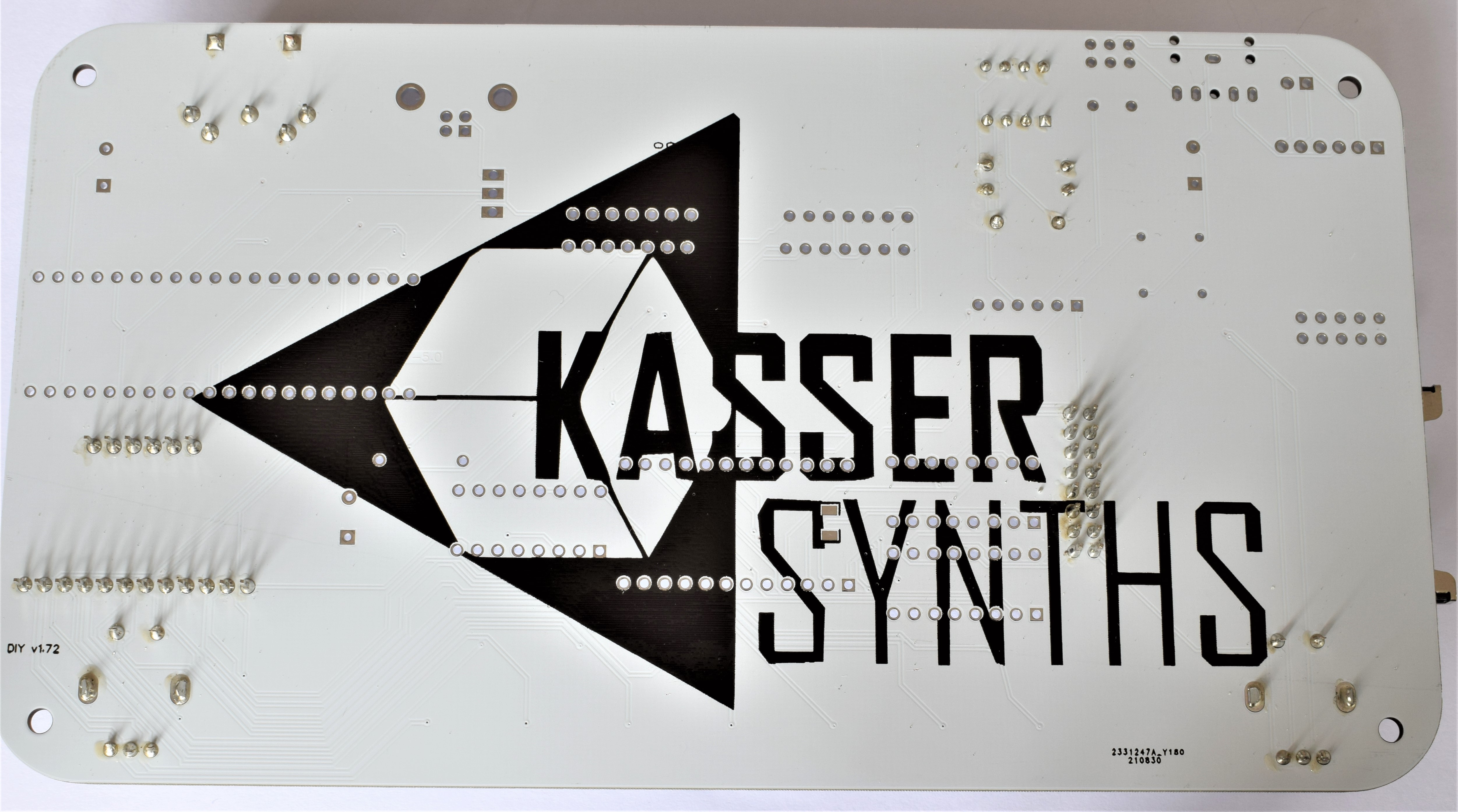
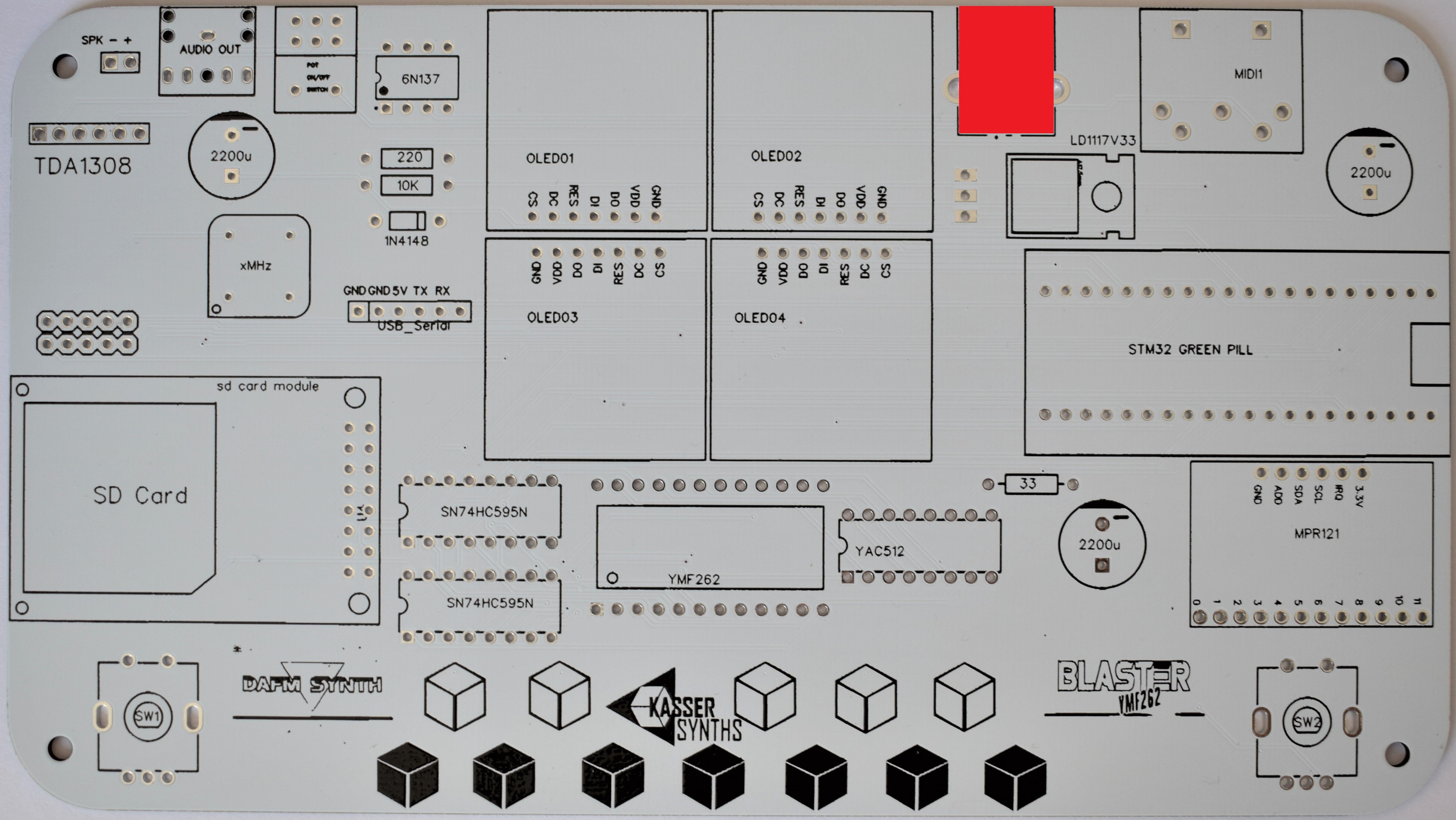
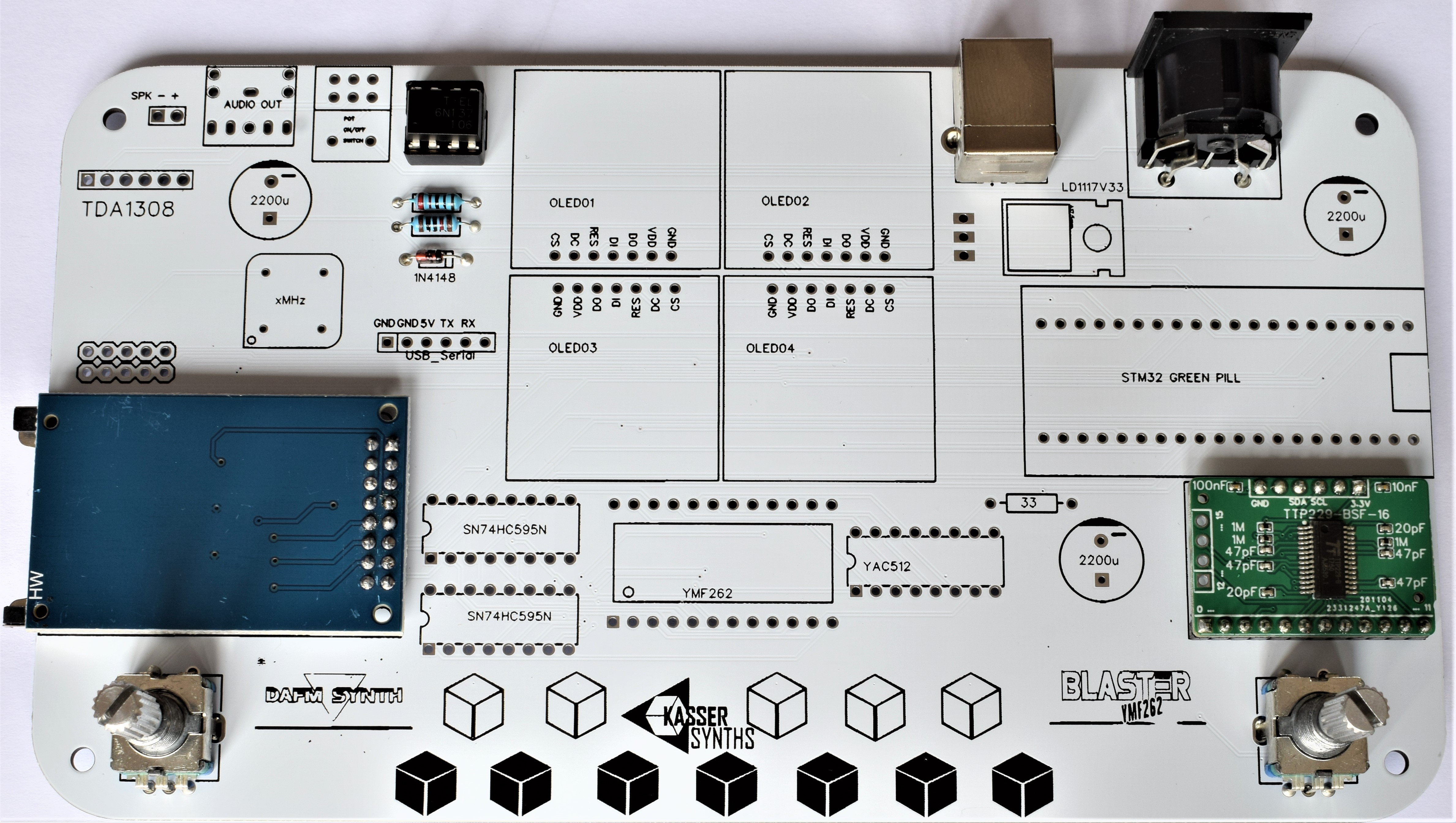
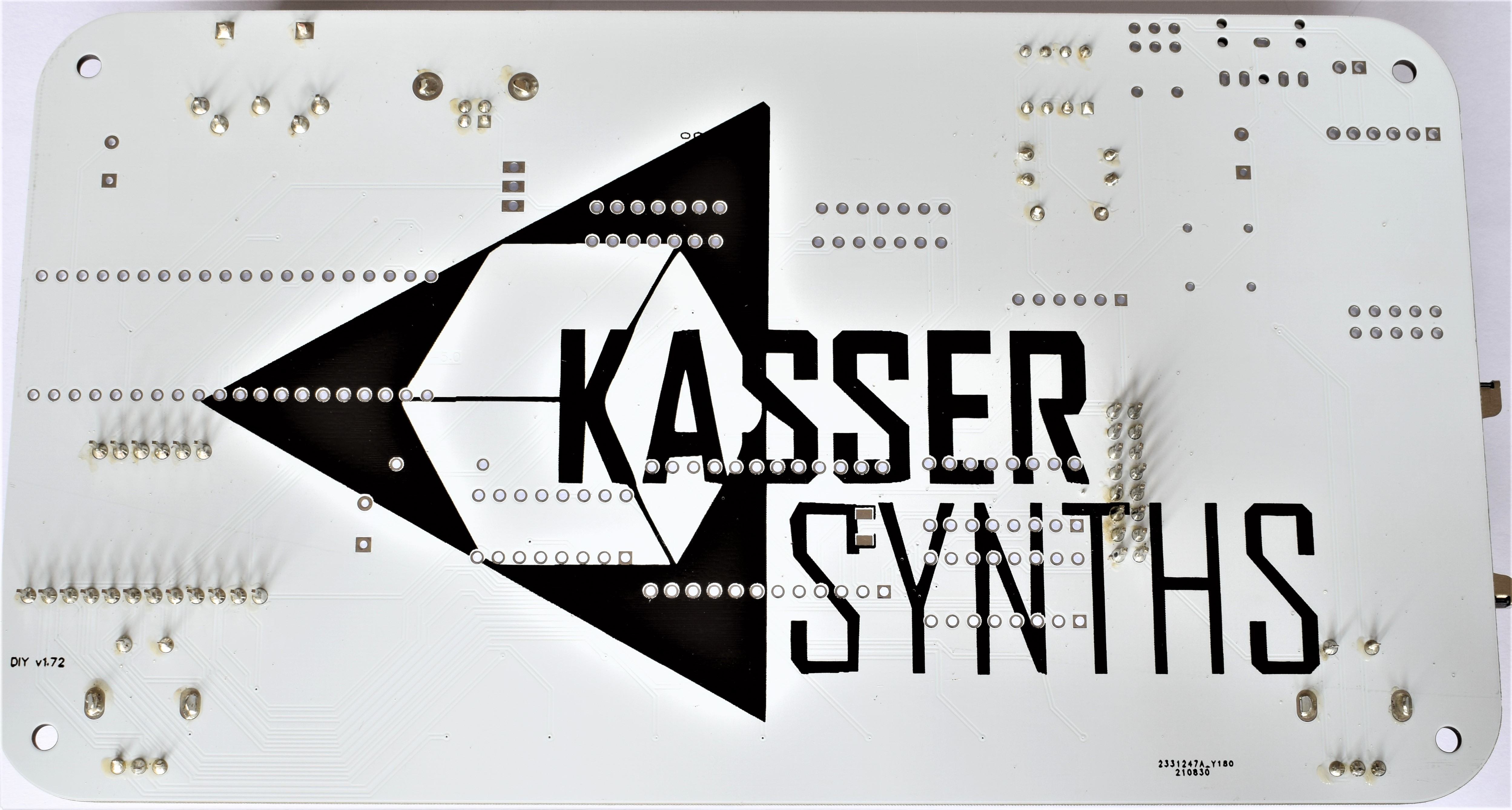
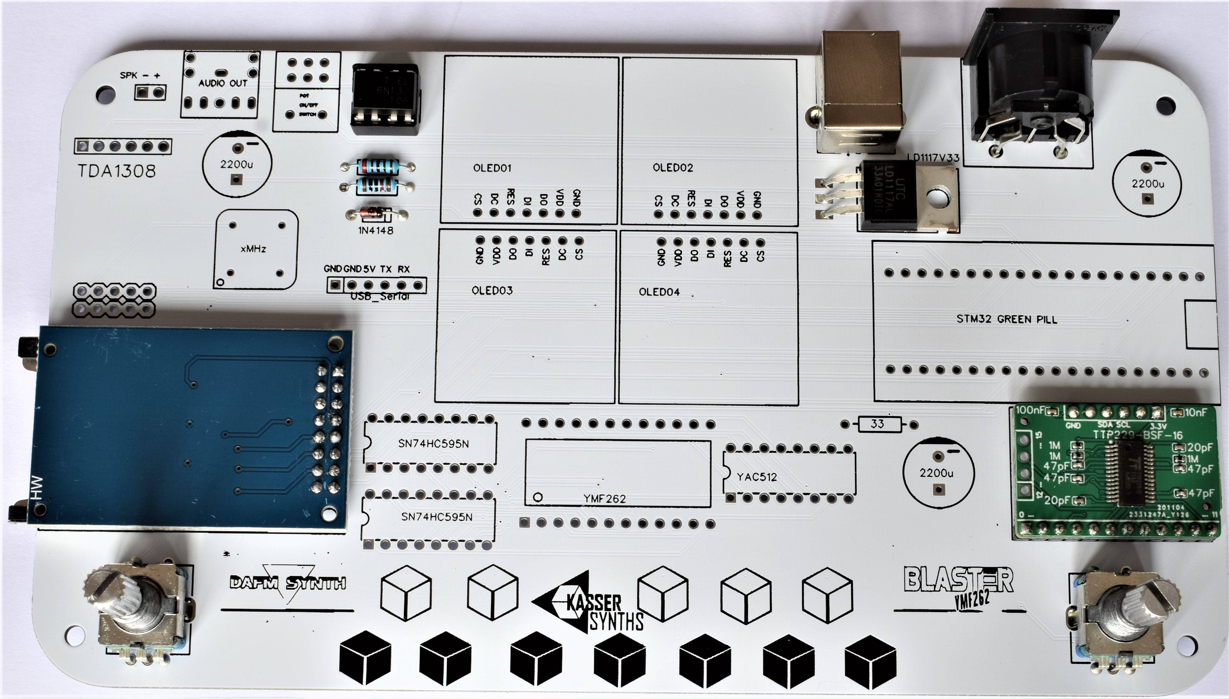
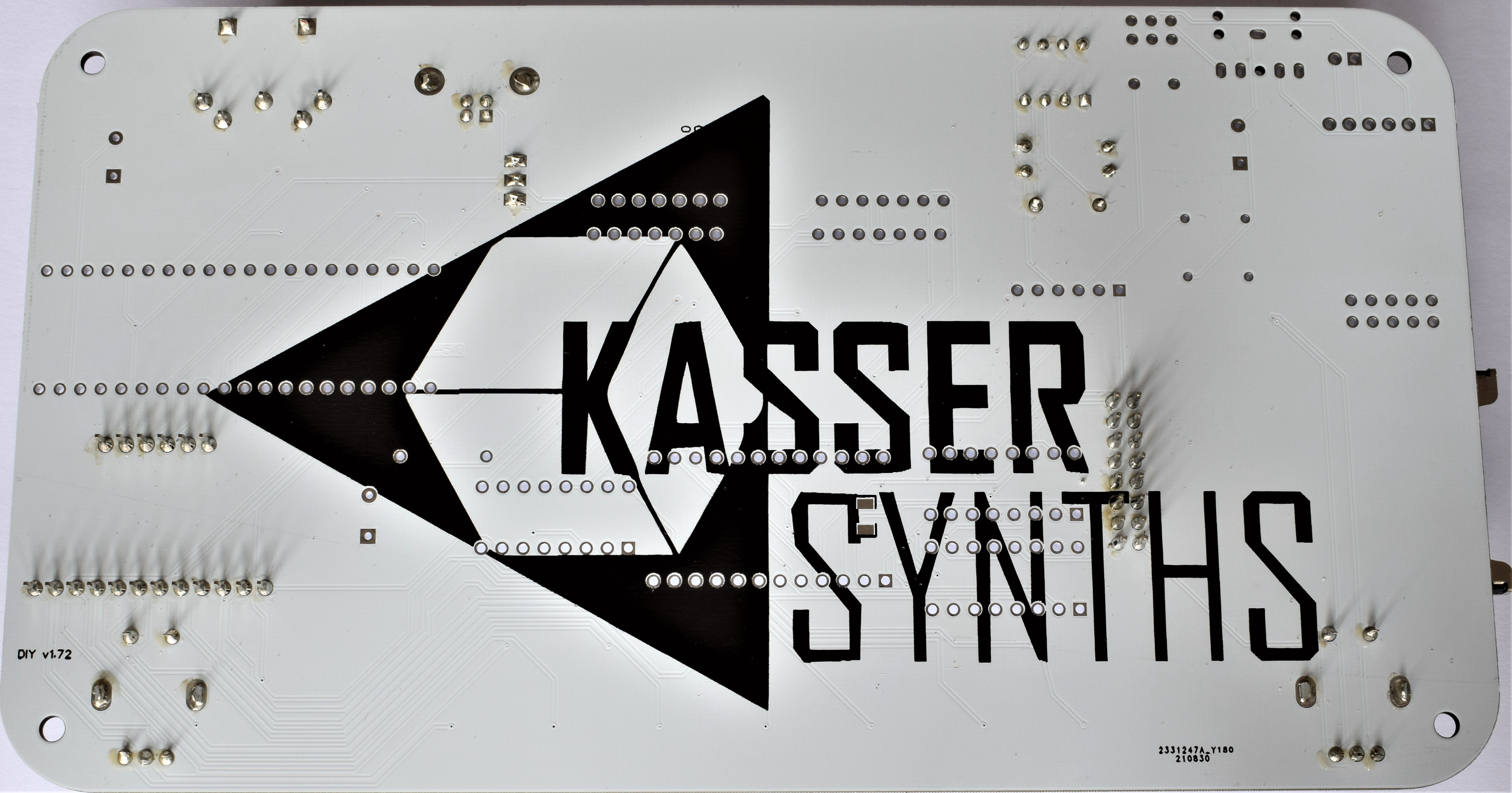
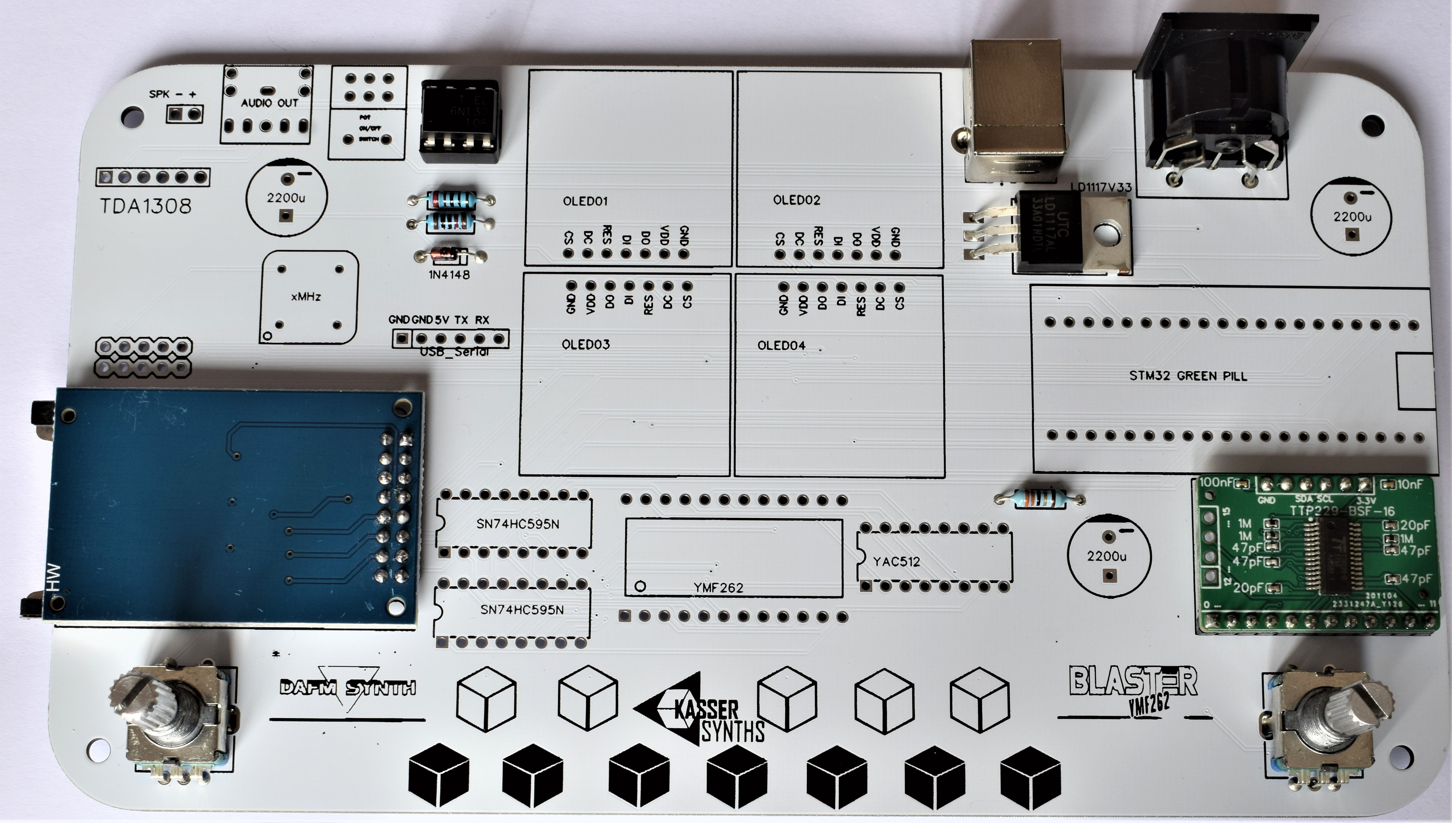
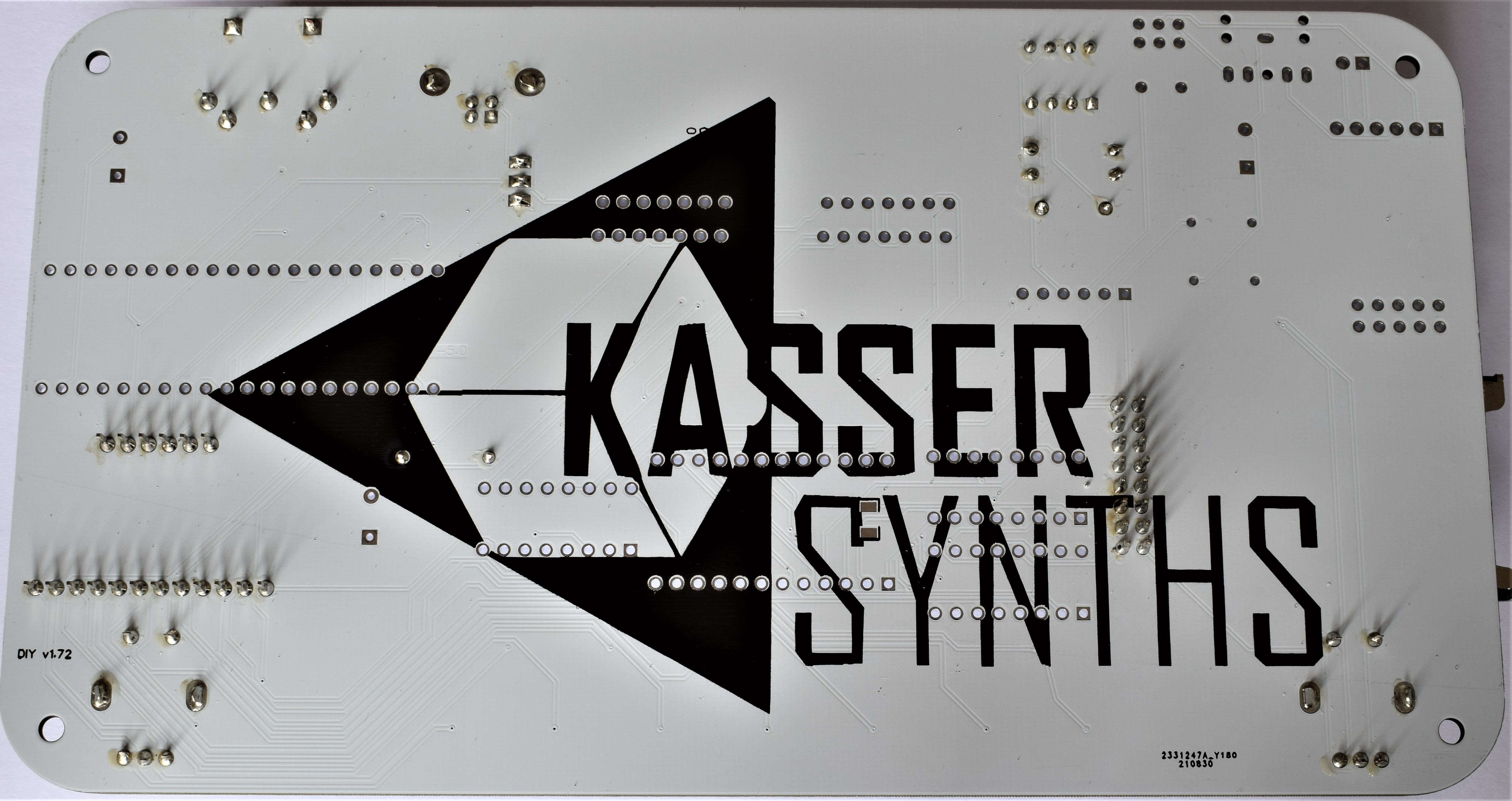
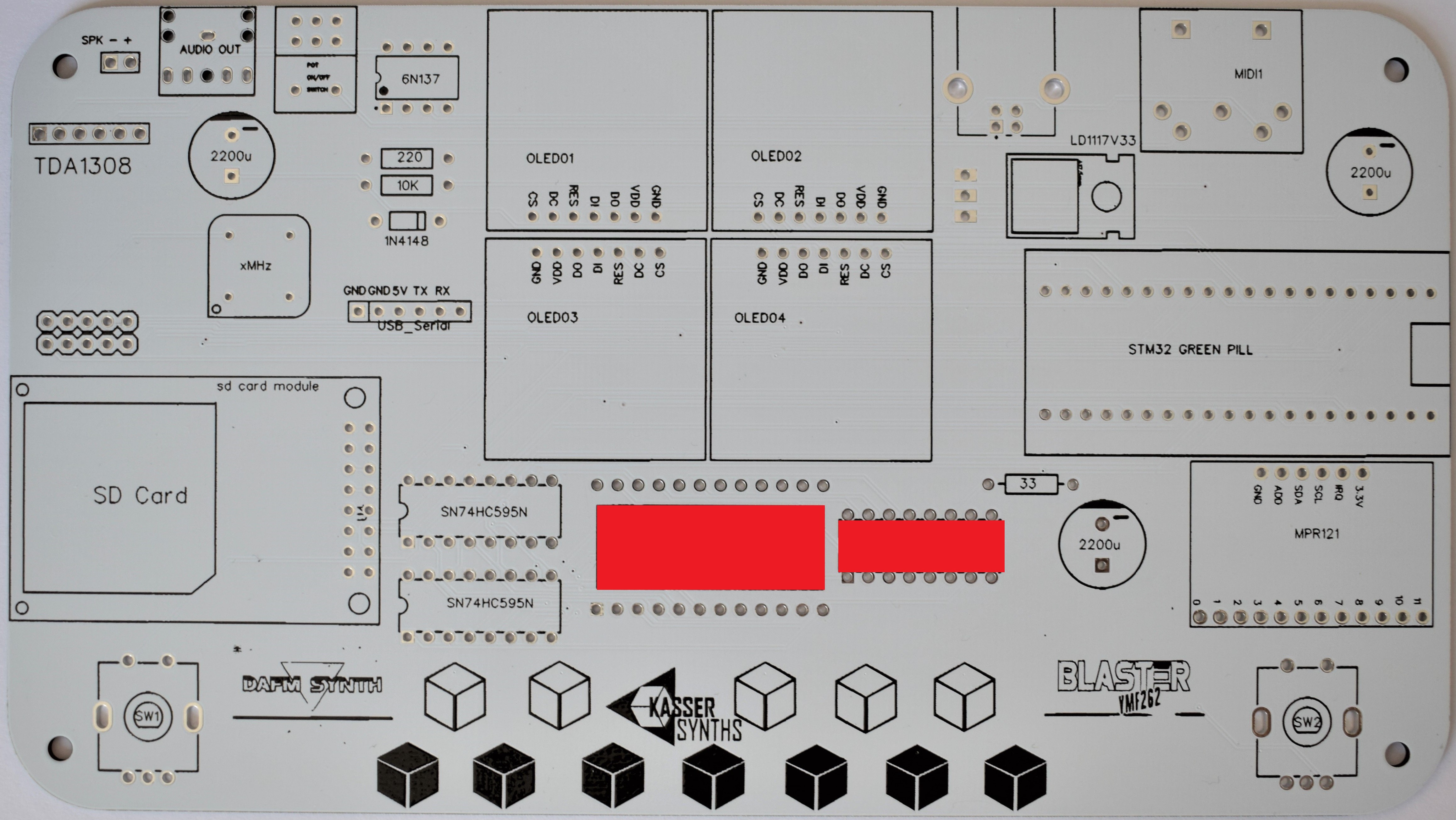
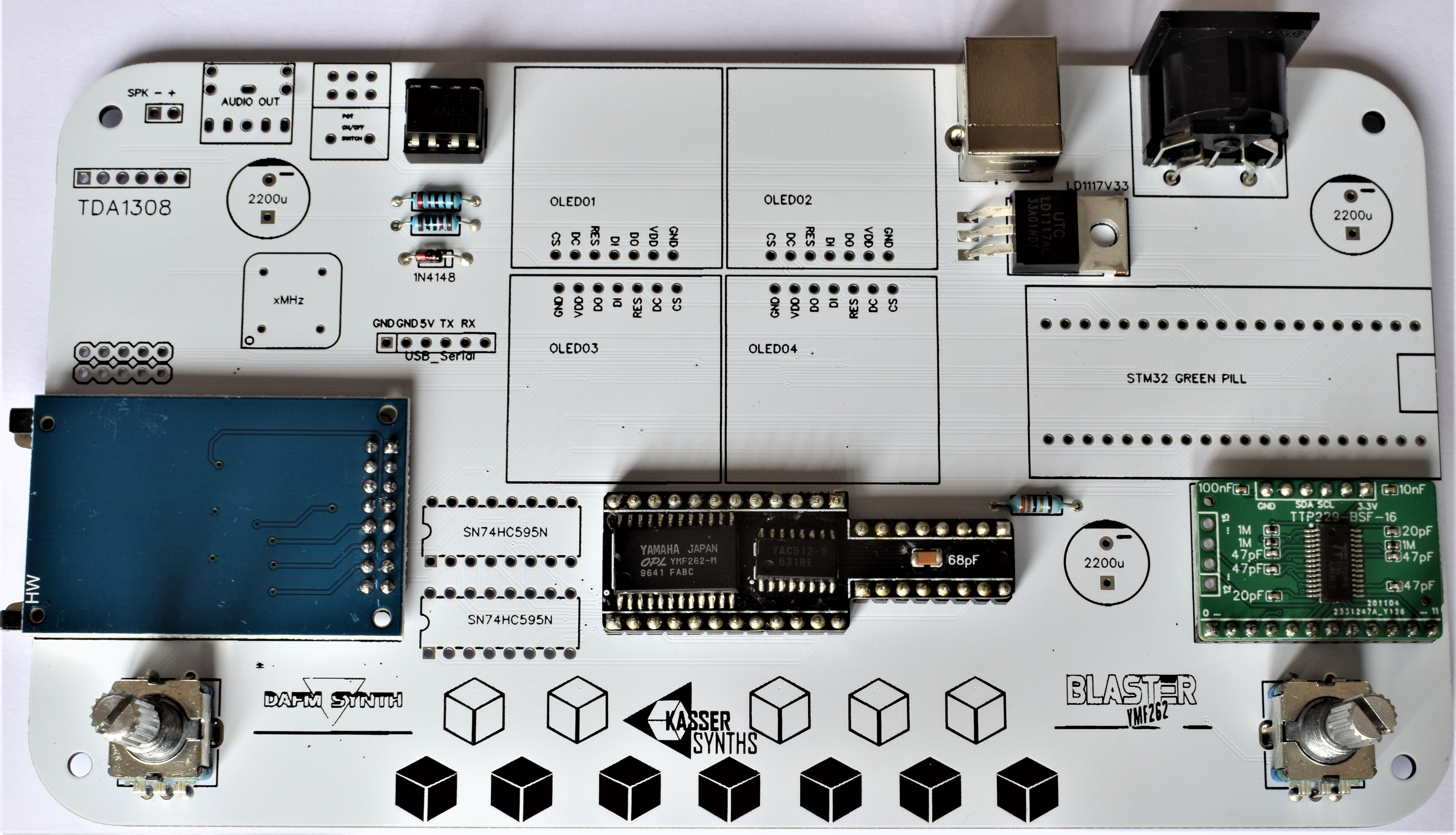
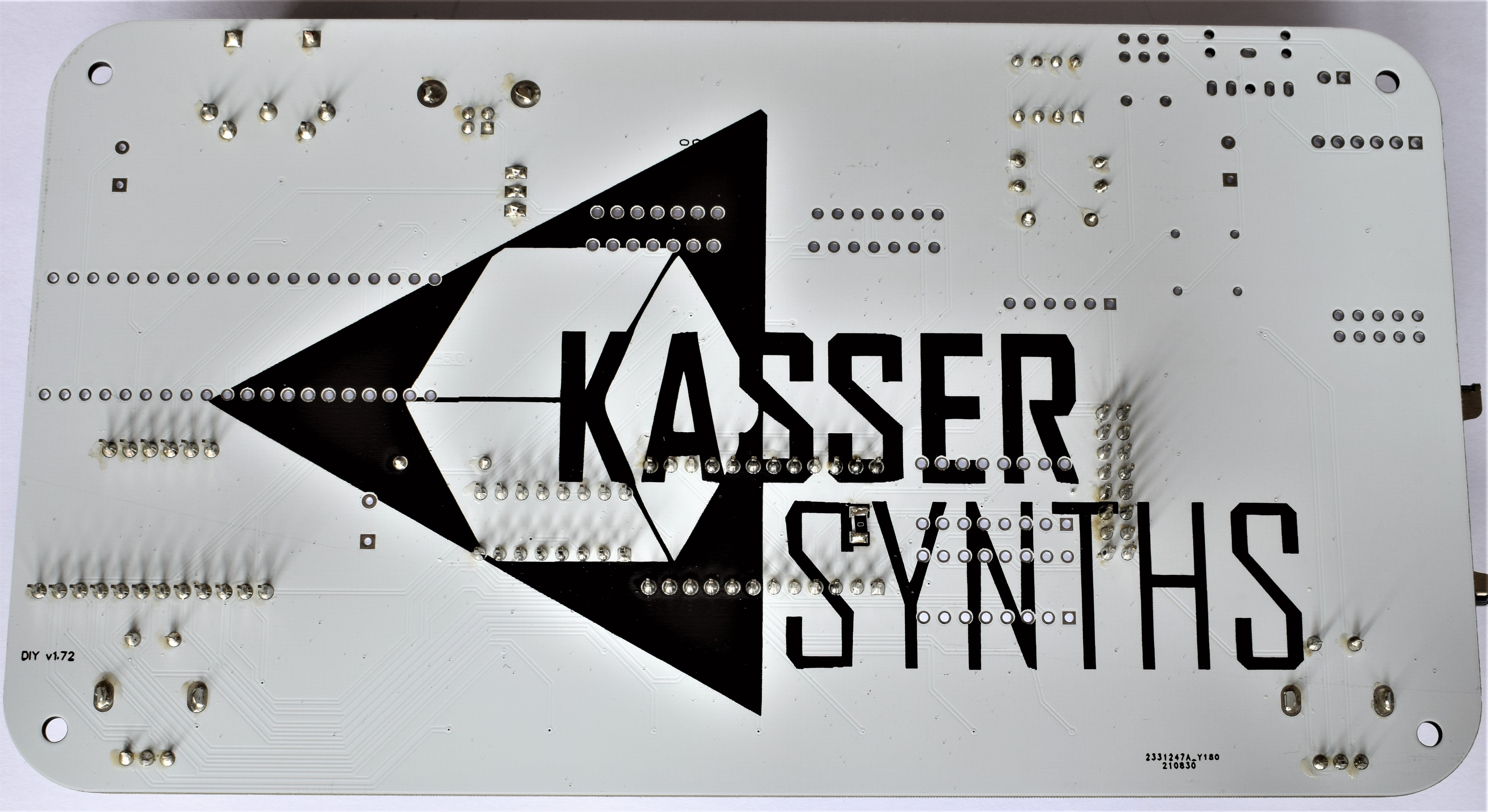
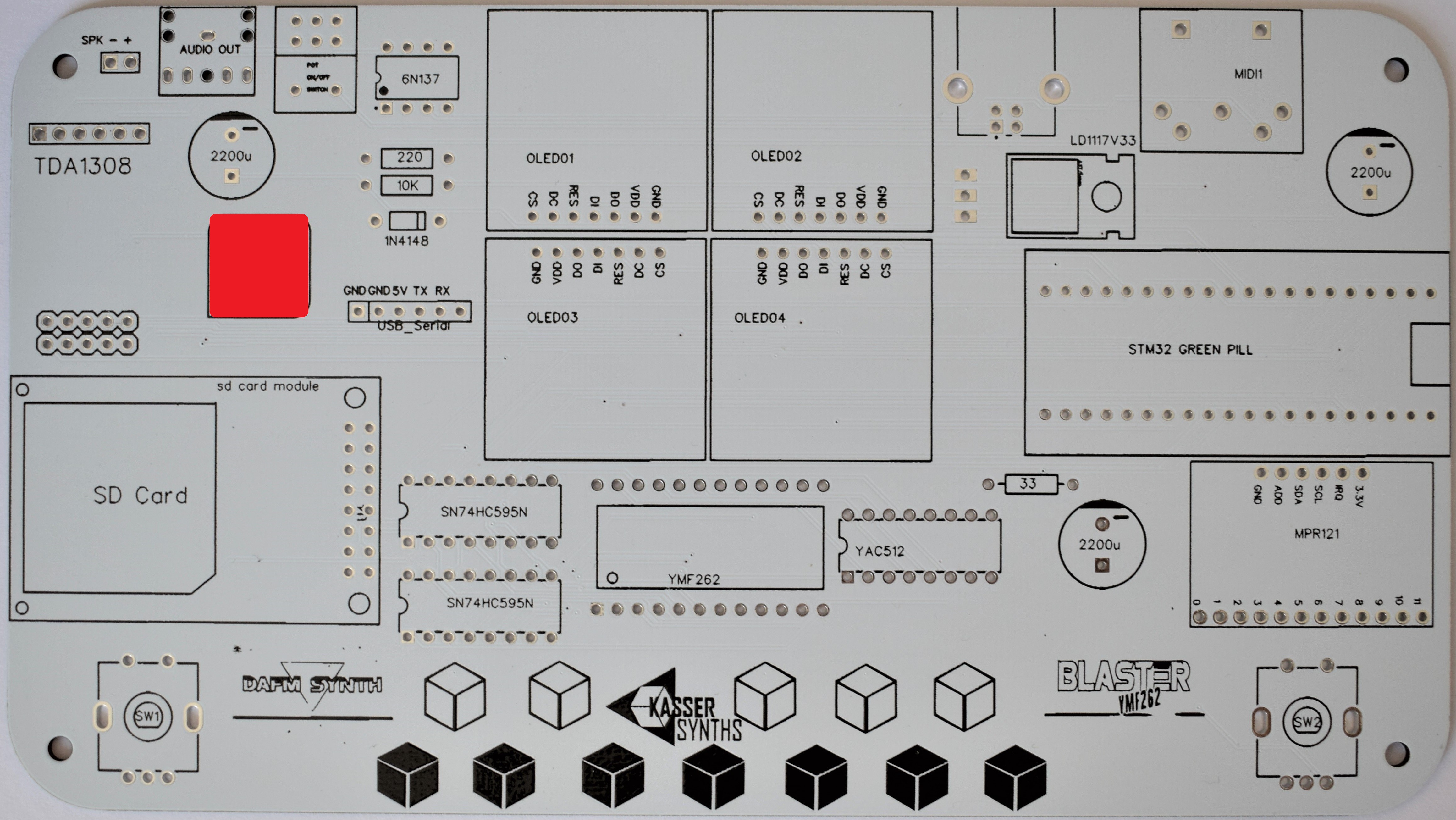
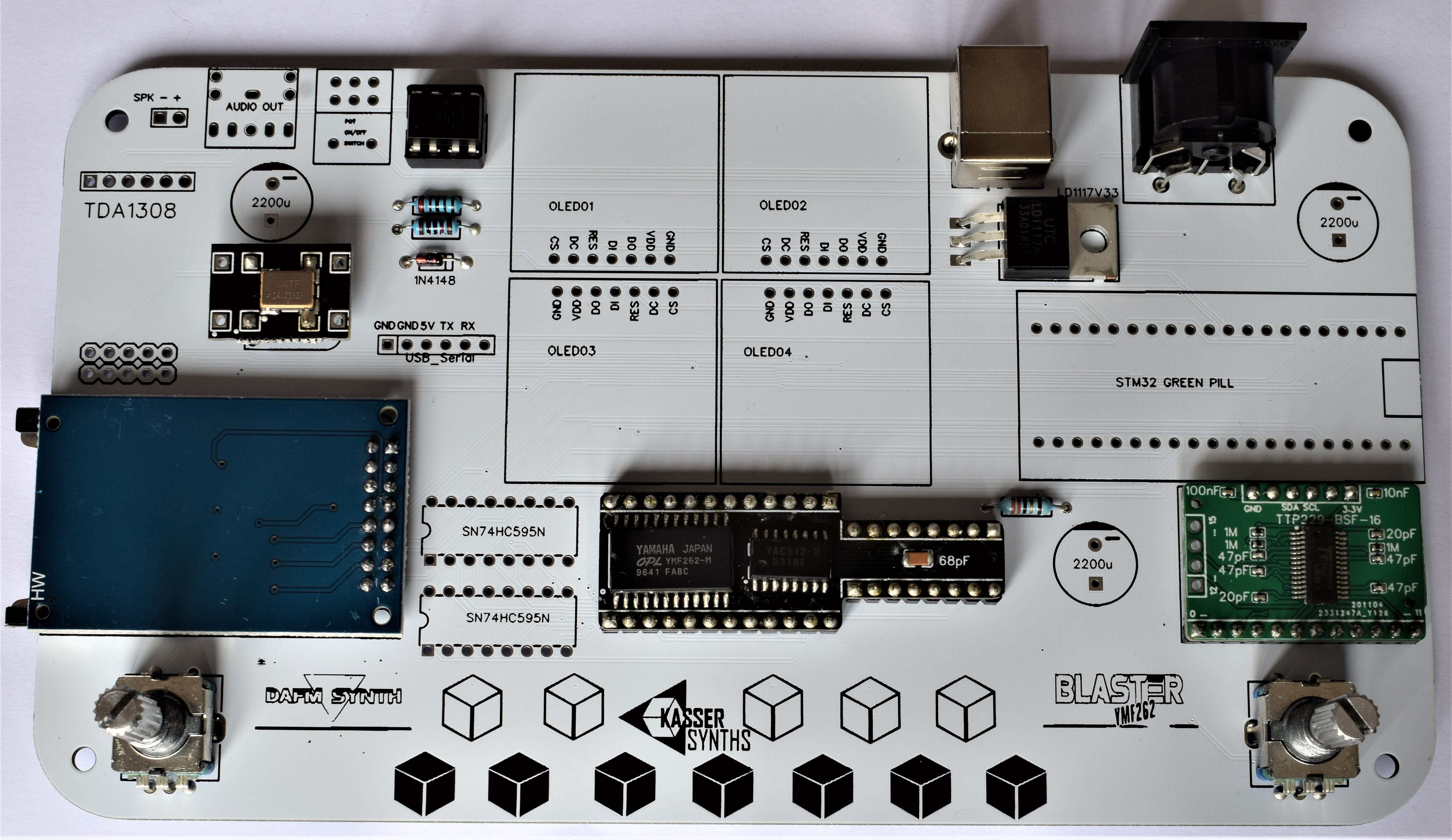
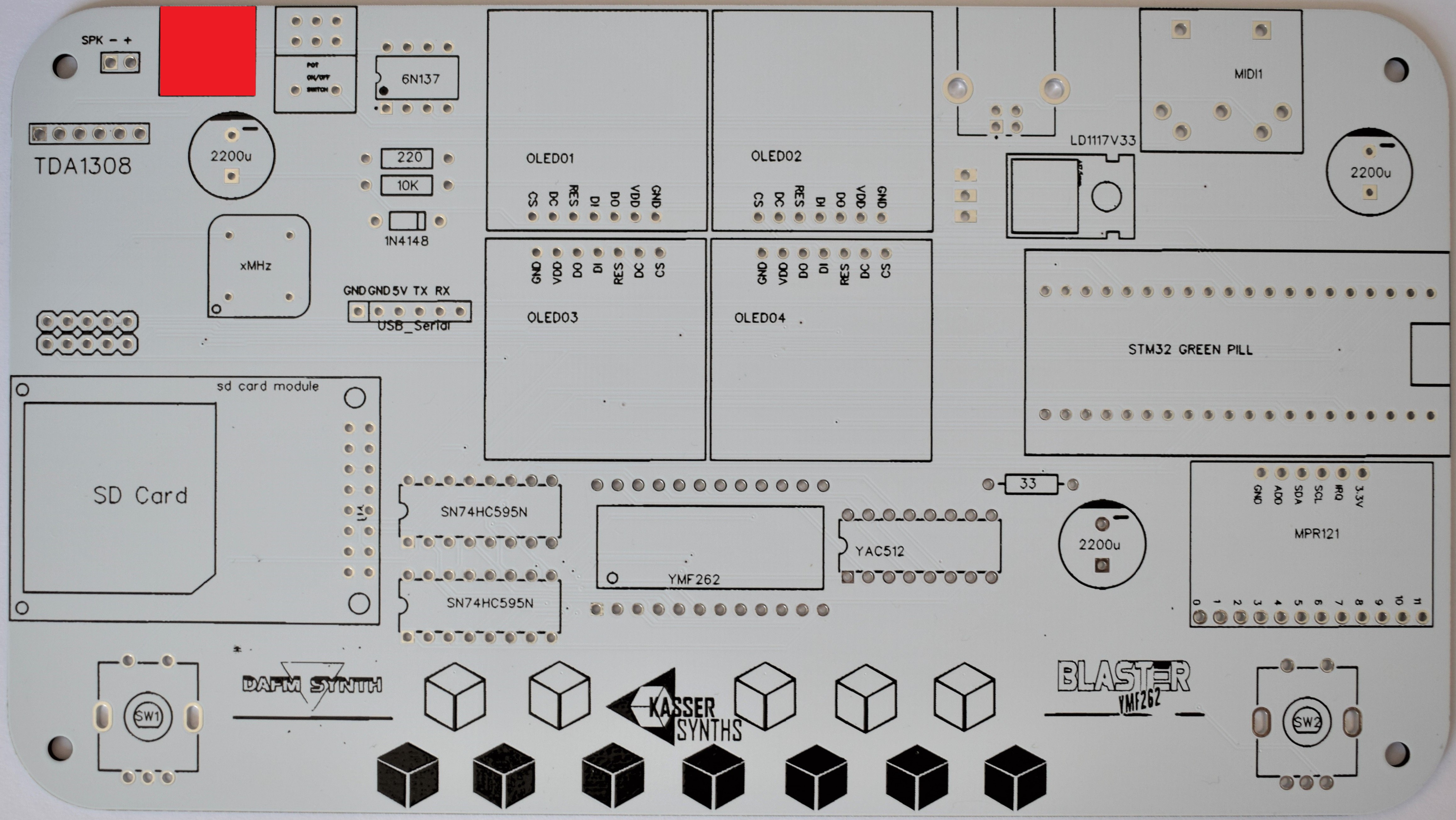
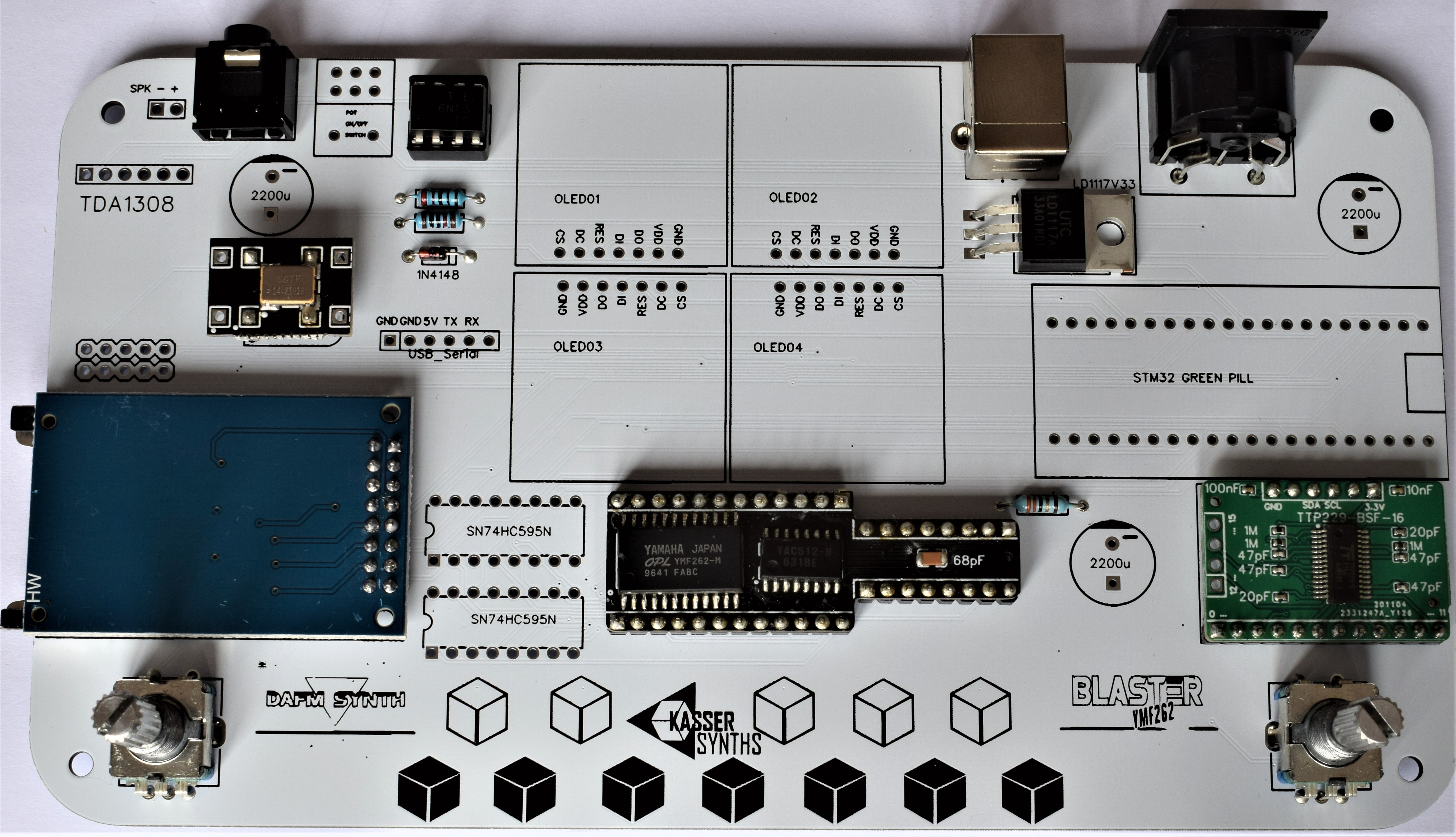
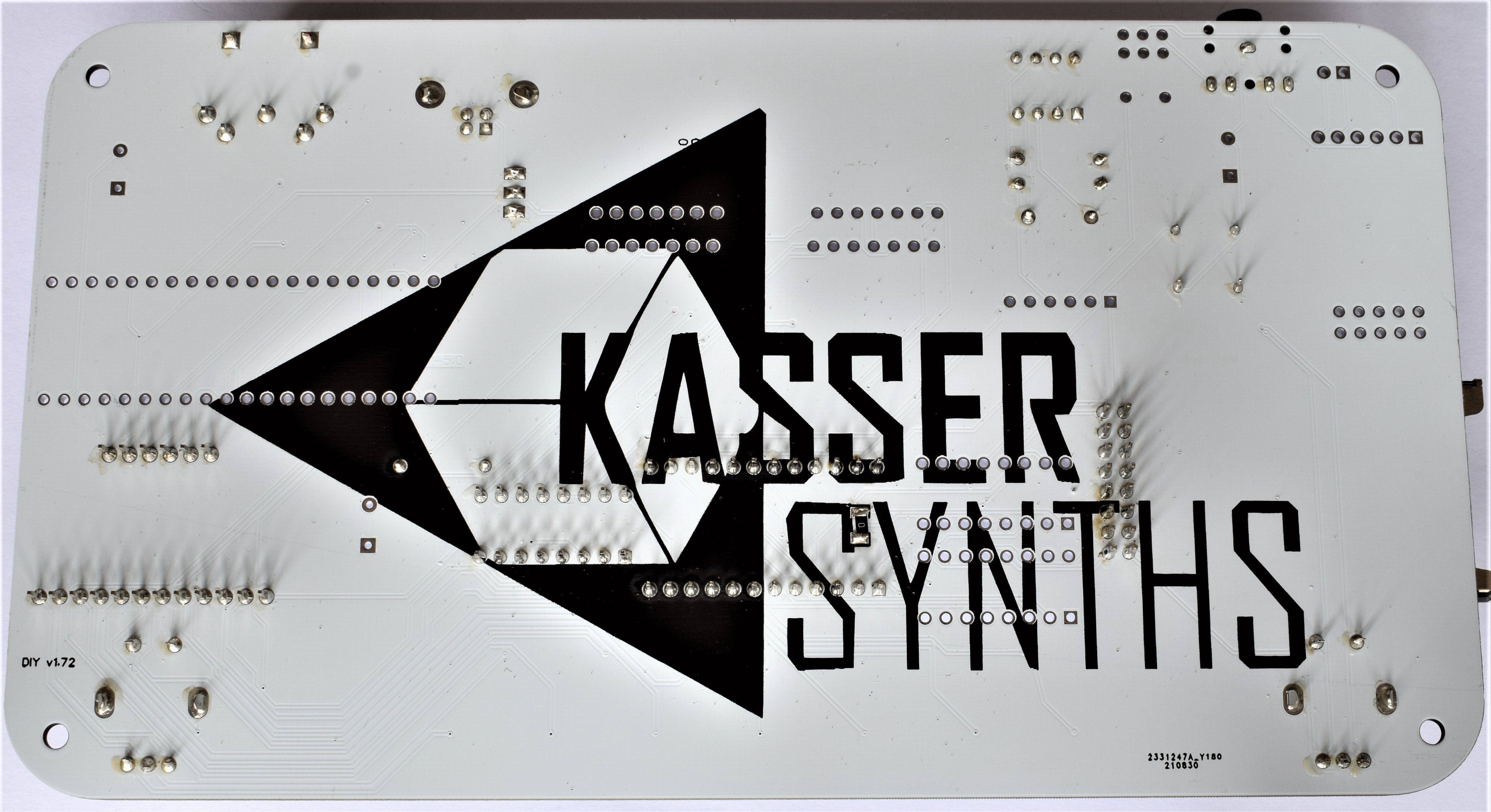
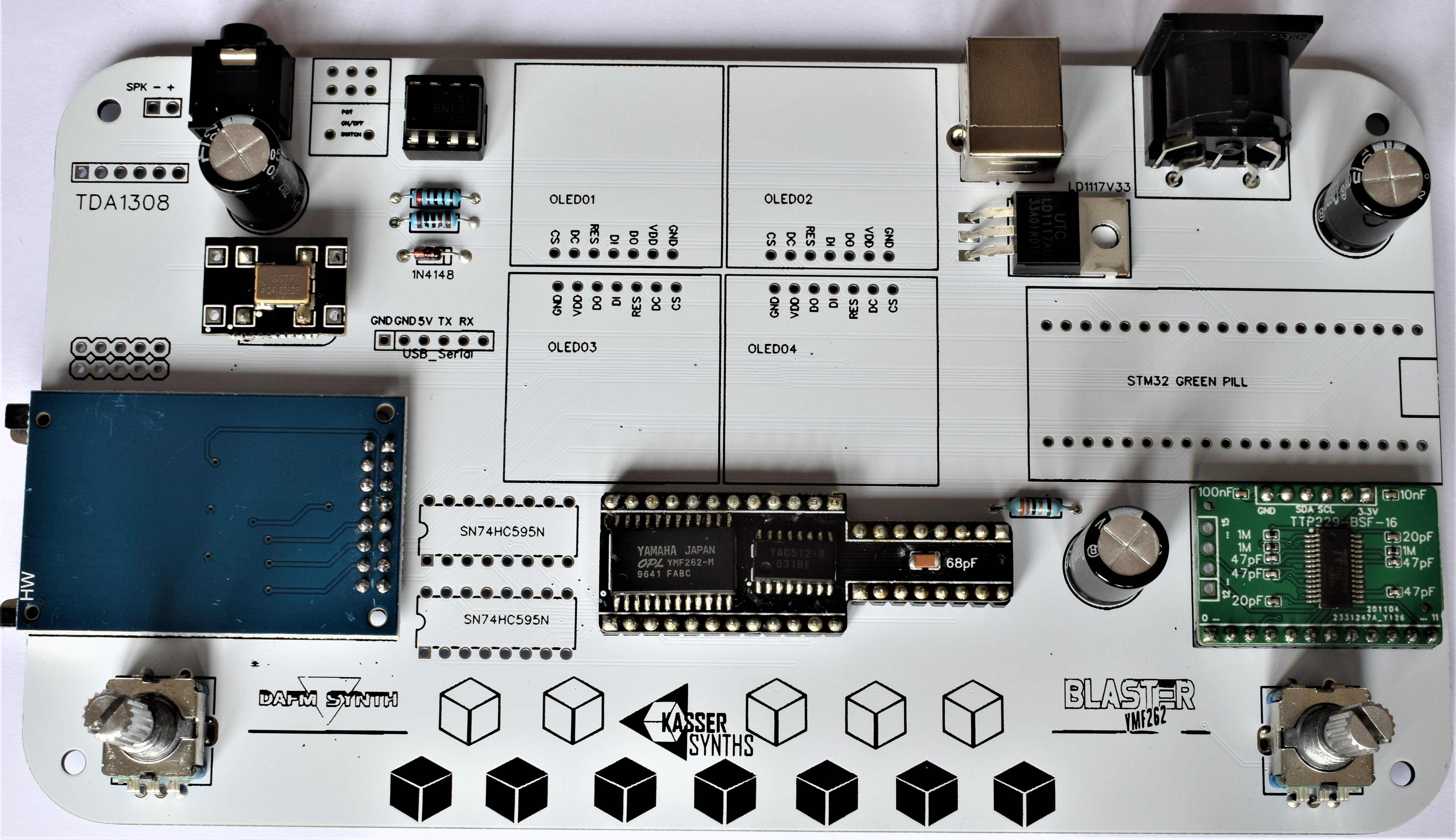
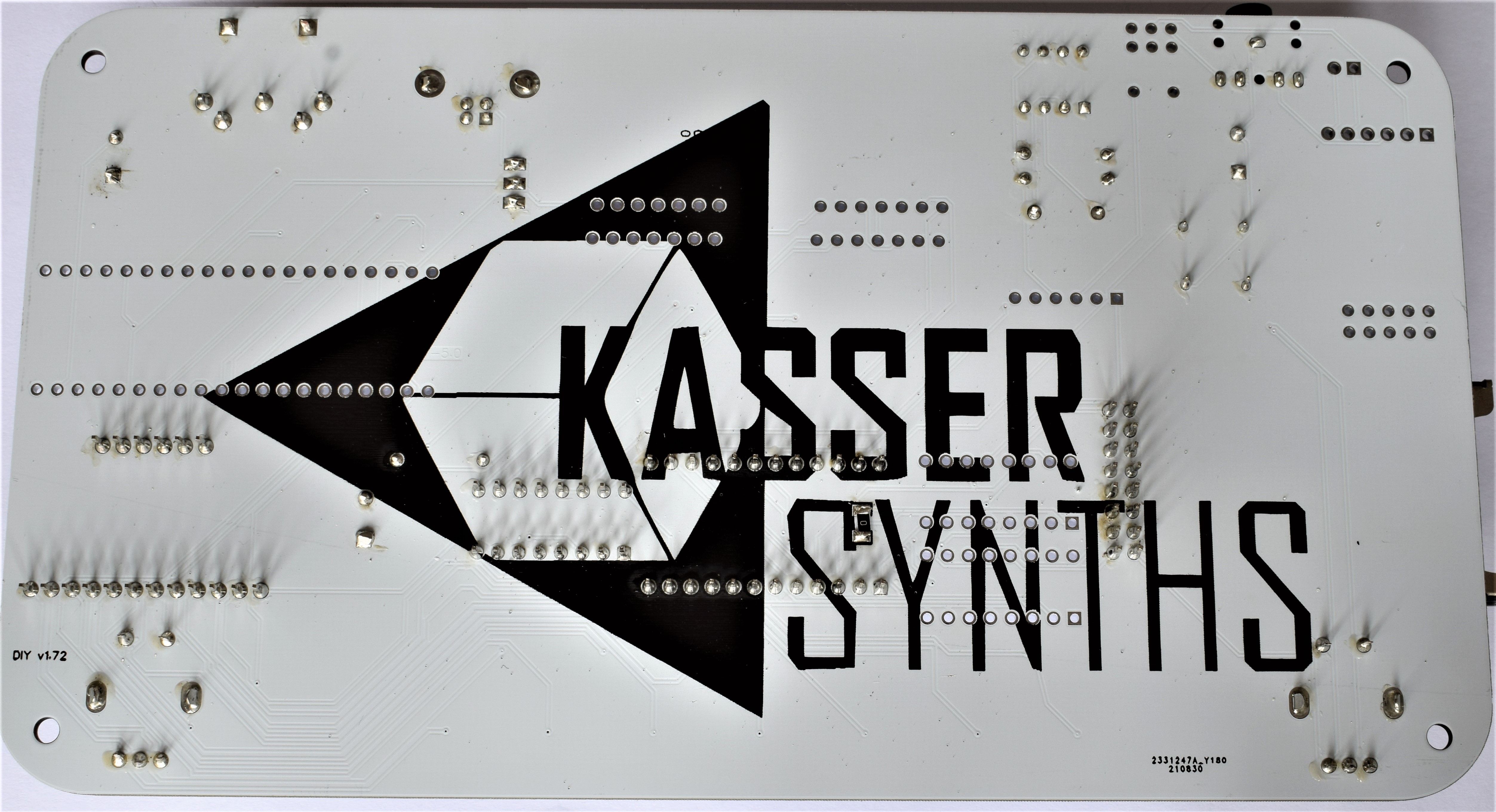
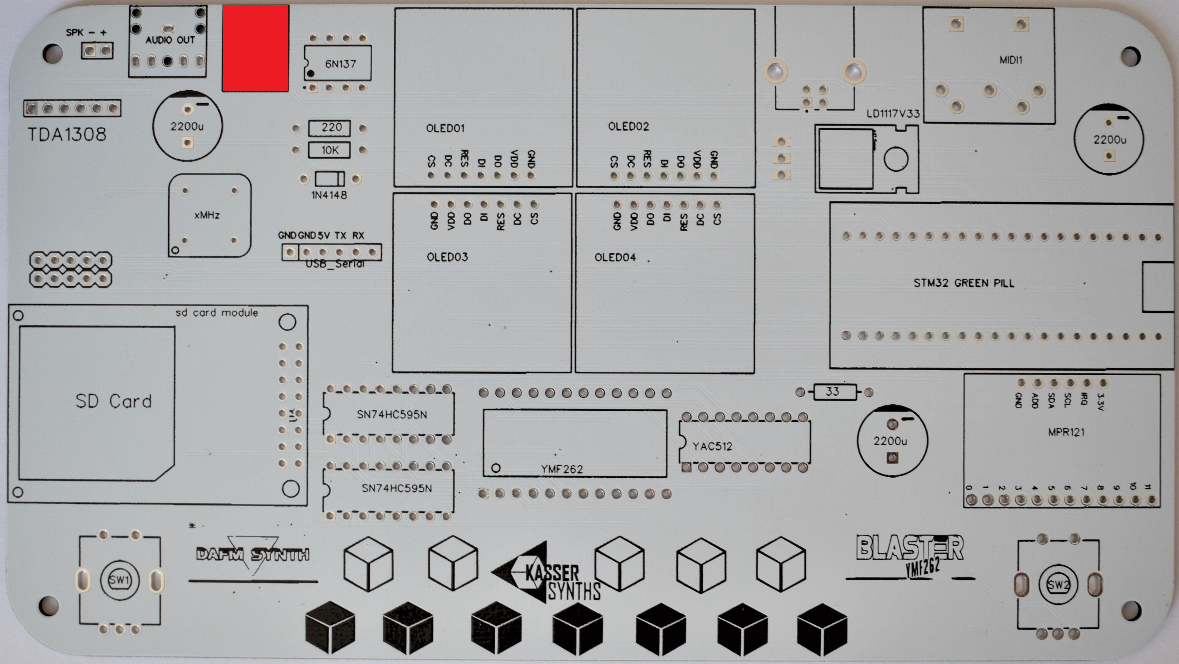
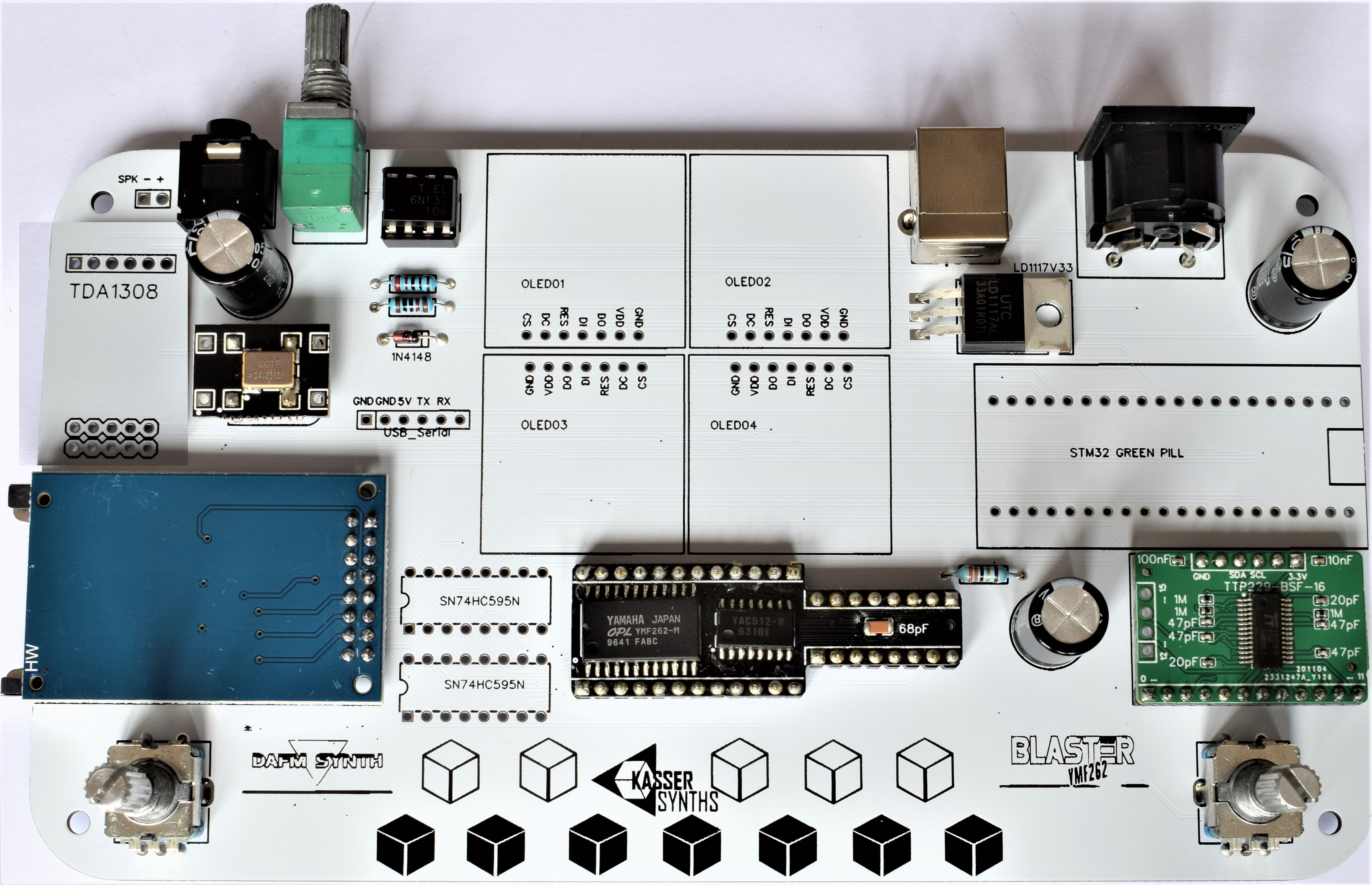
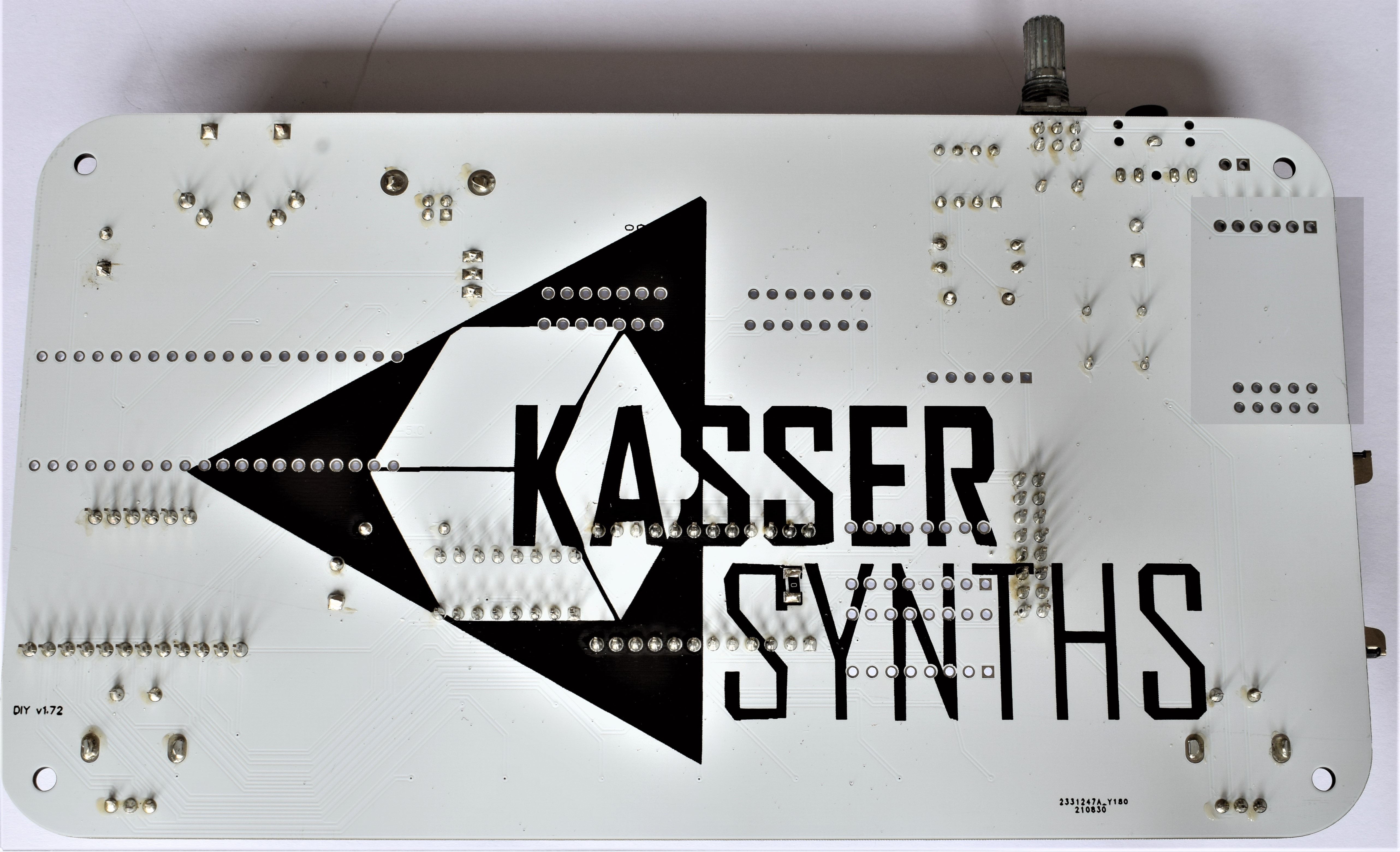
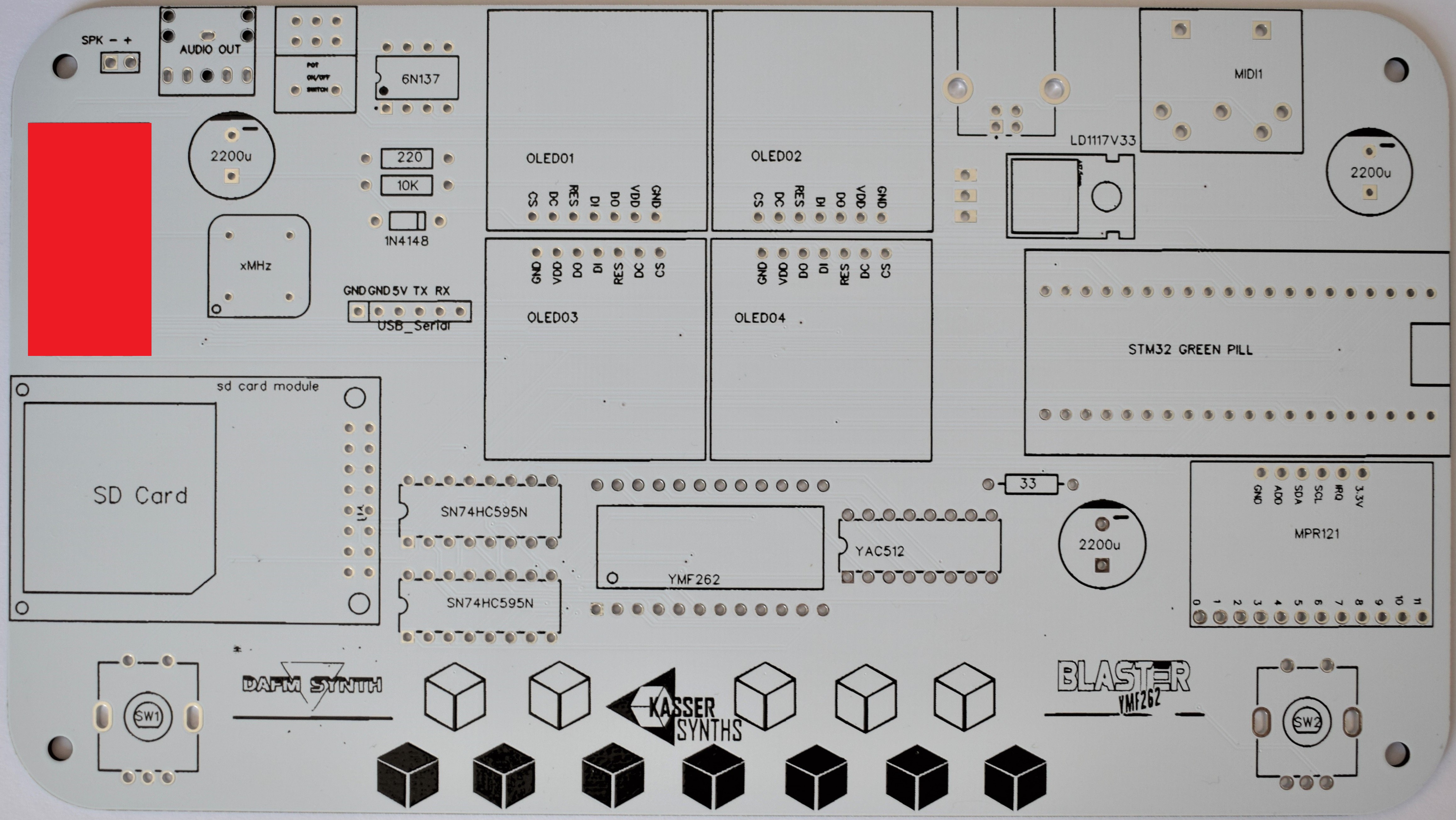
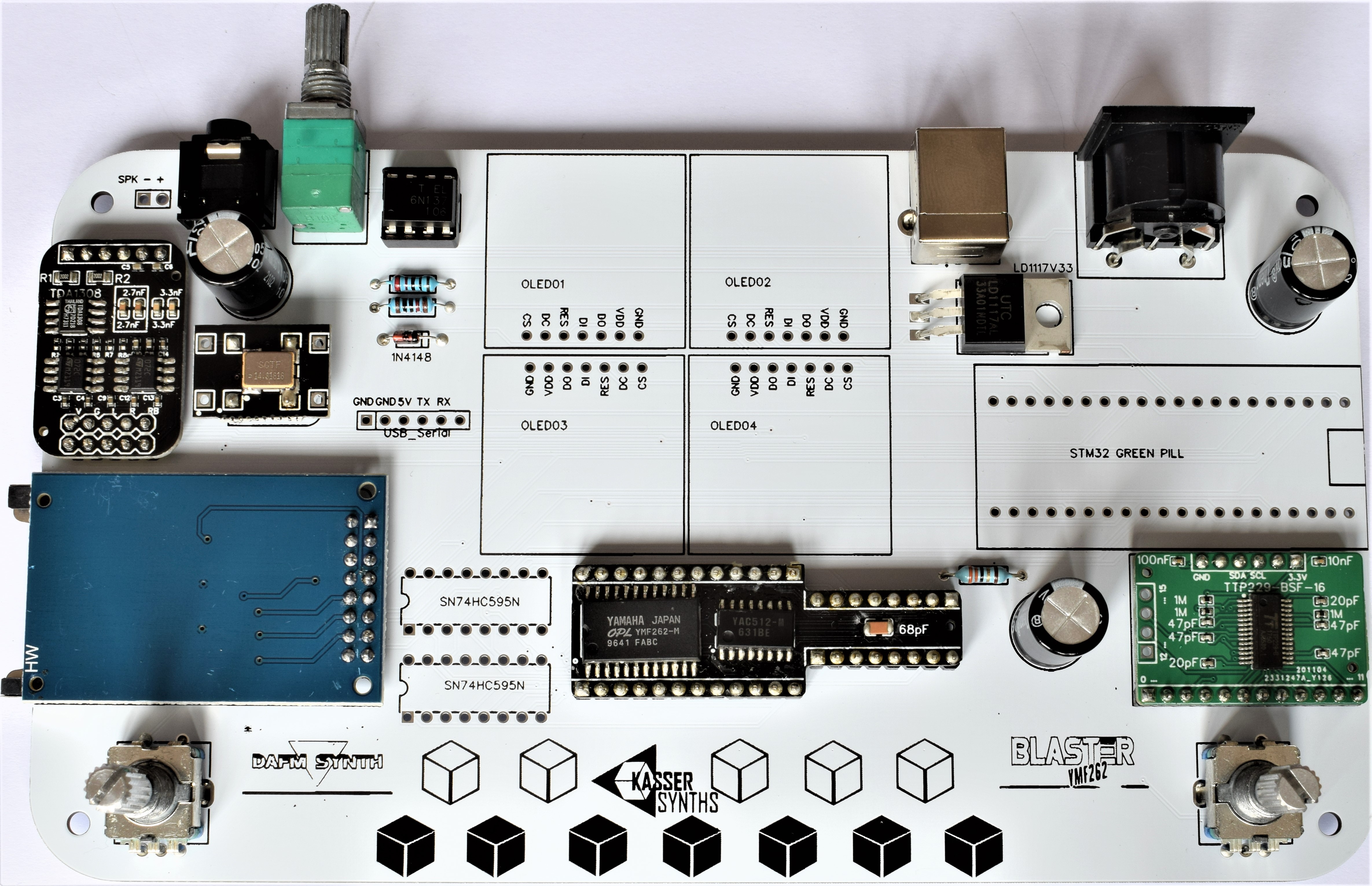
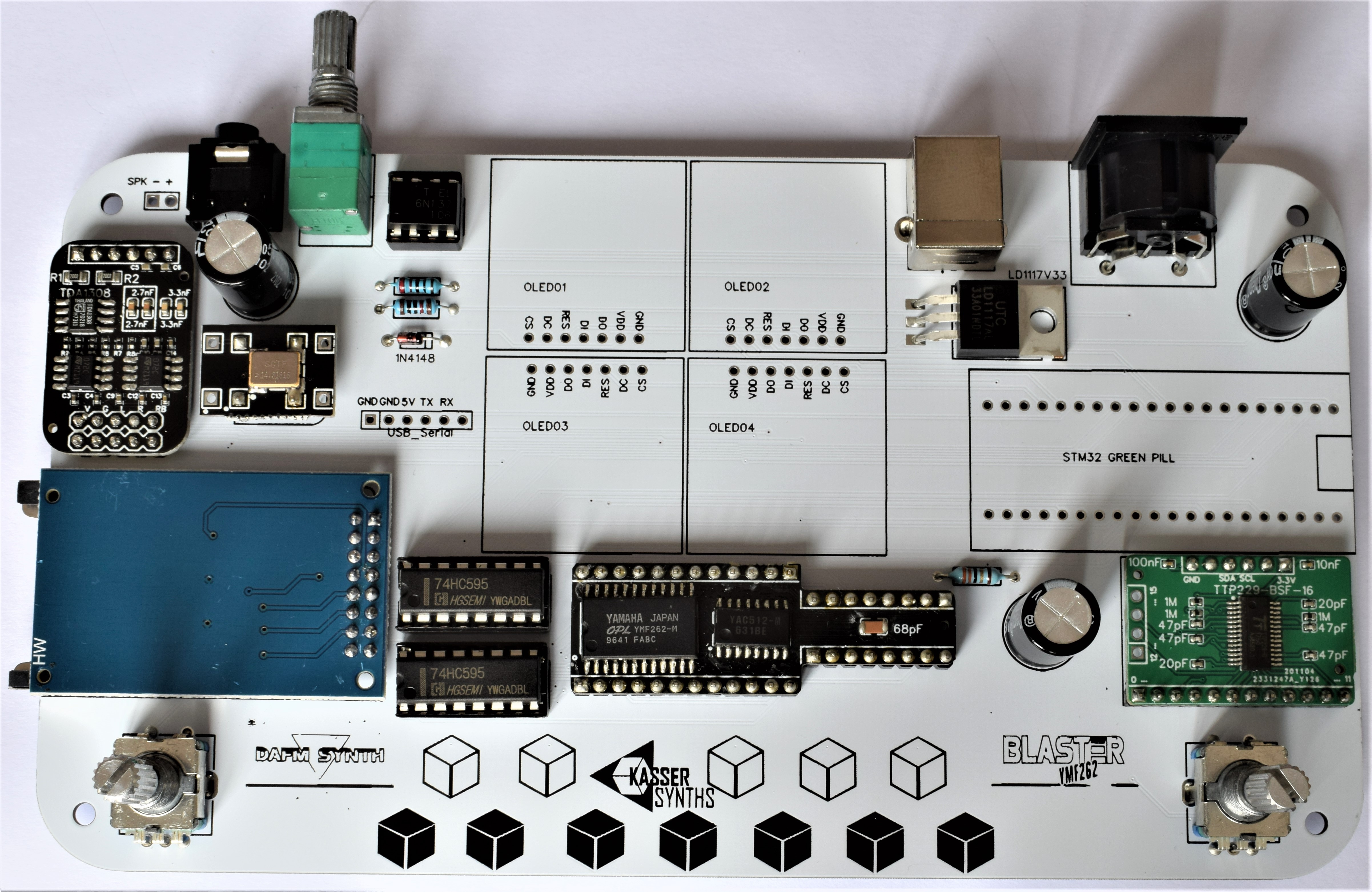
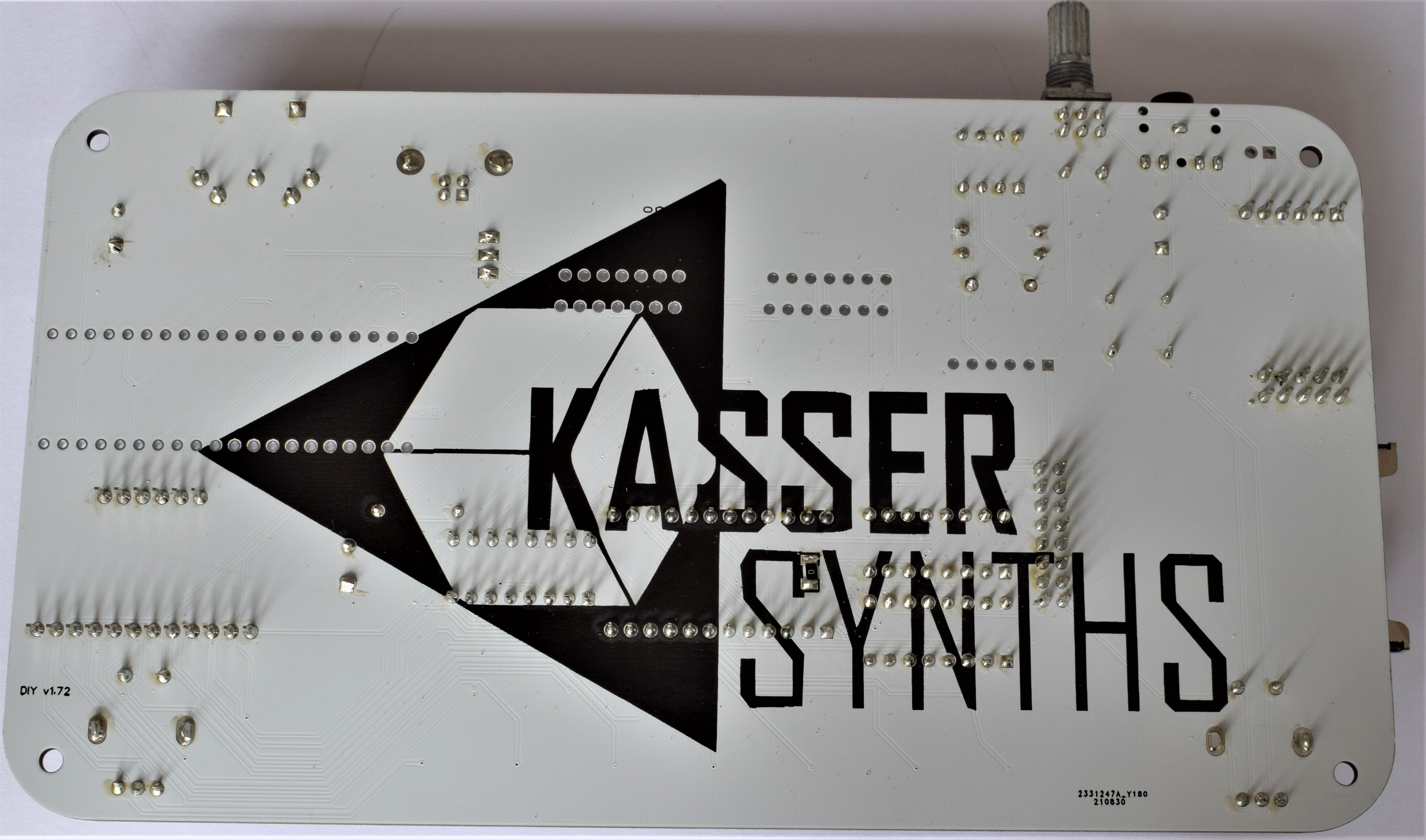
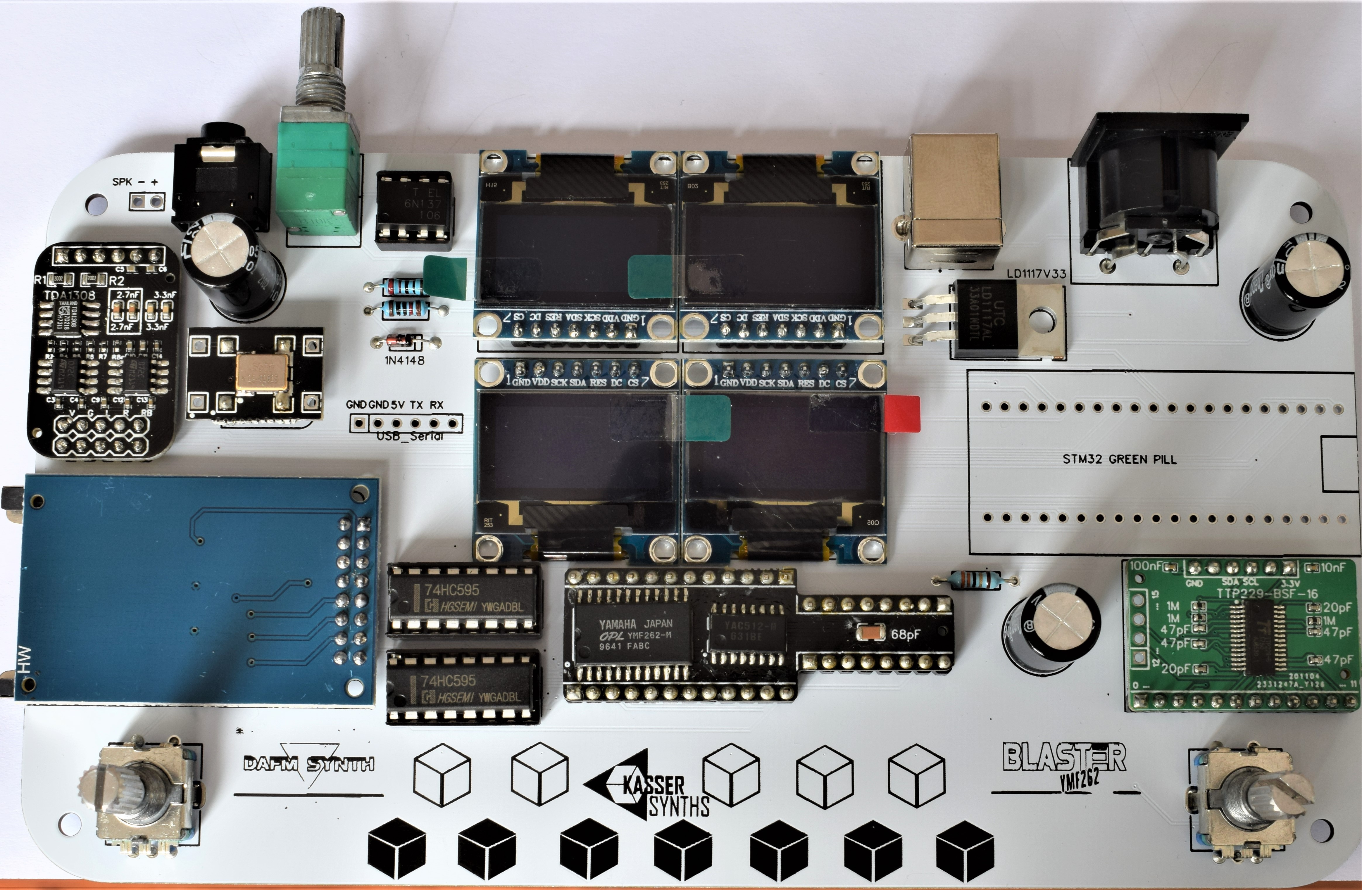
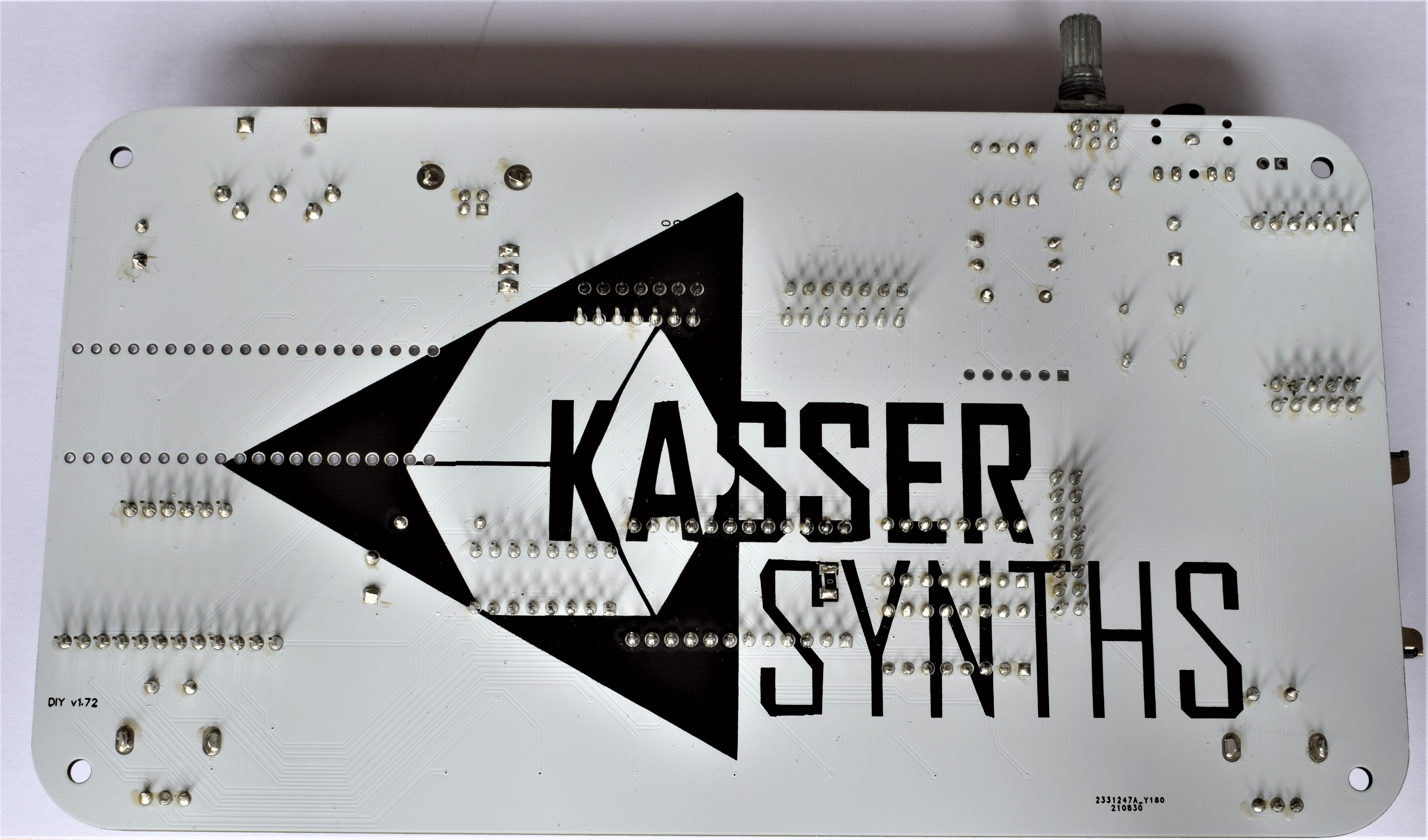
We’ll populate only the top of the board – it’s the side with the KASSER SYNTHS and BLASTER YMF262 logos. Here’s a shot of the board for reference.
-
3MIDI In
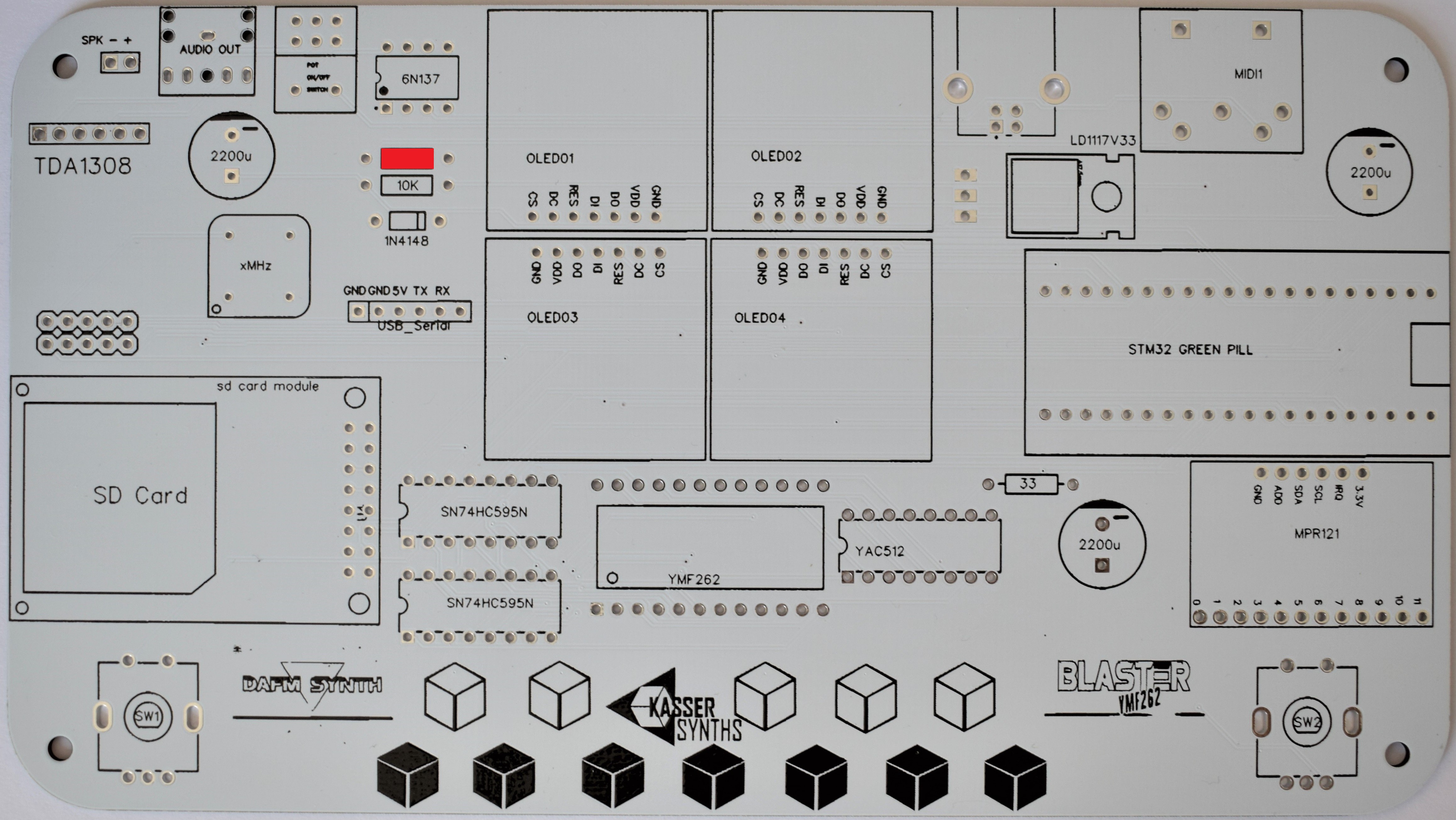
220Ω x 1 (red, red, black, black, brown)
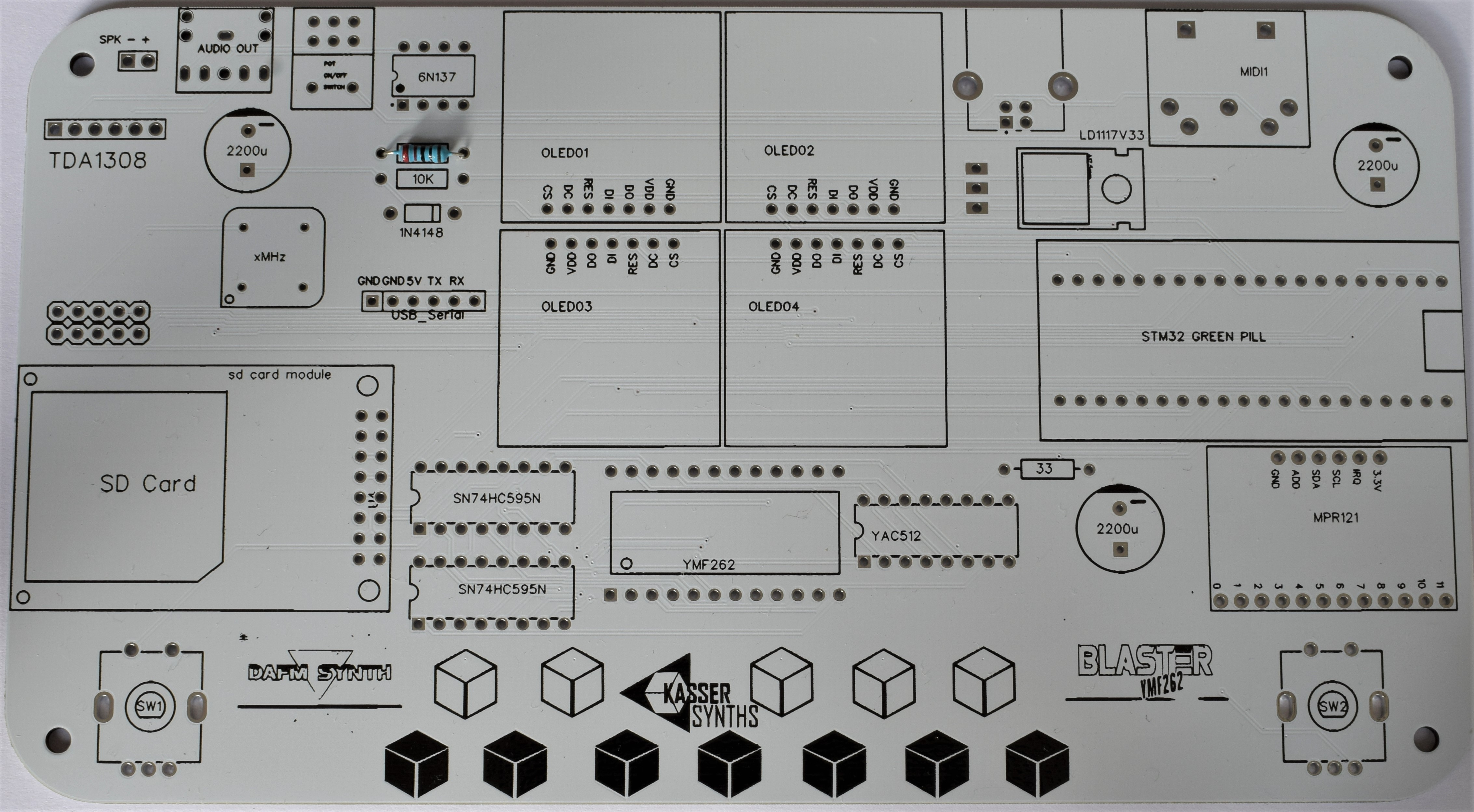
Resistors are not polarized, so it doesn’t matter which way around they go in. Bend the legs into a staple shape,and fold the legs over once you’ve inserted them into the board.
![]()
You don’t need to fold them over too much, it’s just so they don’t fall out when you flip the board over. It’ll make it easier to solder and snip off the legs if you don’t.
10kΩ x 1 (brown, black, orange, gold)
![]()
Solder and snip.
Diode 1N4148
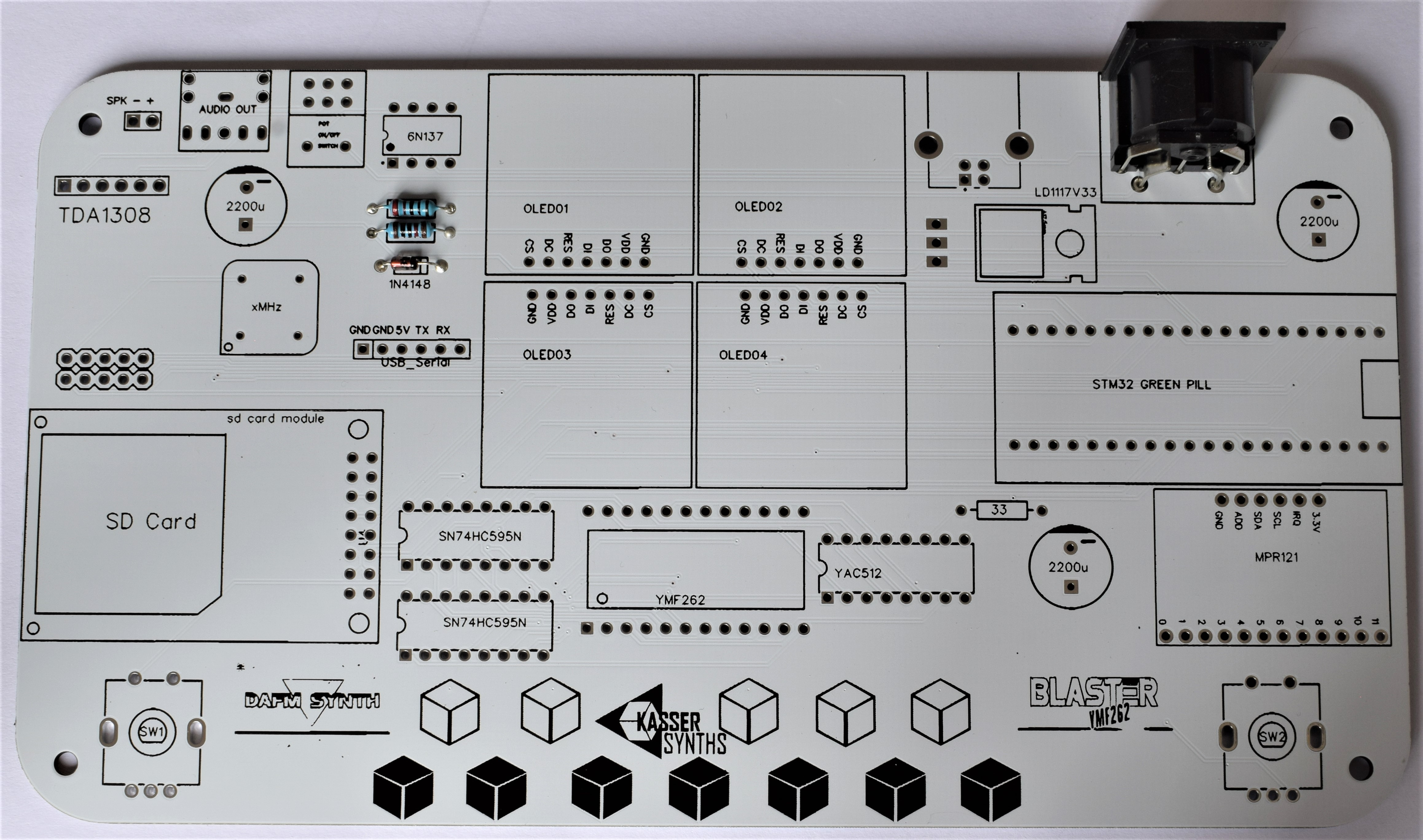
The 1N4148 has a see-through glass body. It is part of the MIDI input circuit. Solder and snip. Watch out, the diodes are polarized, so pay close attention to which side the line marking on the diode body goes – it’s marked with a thicker white line on the PCB.
![]()
5 Pin DIN Connector
![]()
8 Pin Socket
It’s for the 6N137 optocoupler. The side the notch goes is marked on the board by a broken line on the ICs outline.
![]()
-
4SD Card
It is used for saving and loading instrument presets in the DAFM synth.
![]()
-
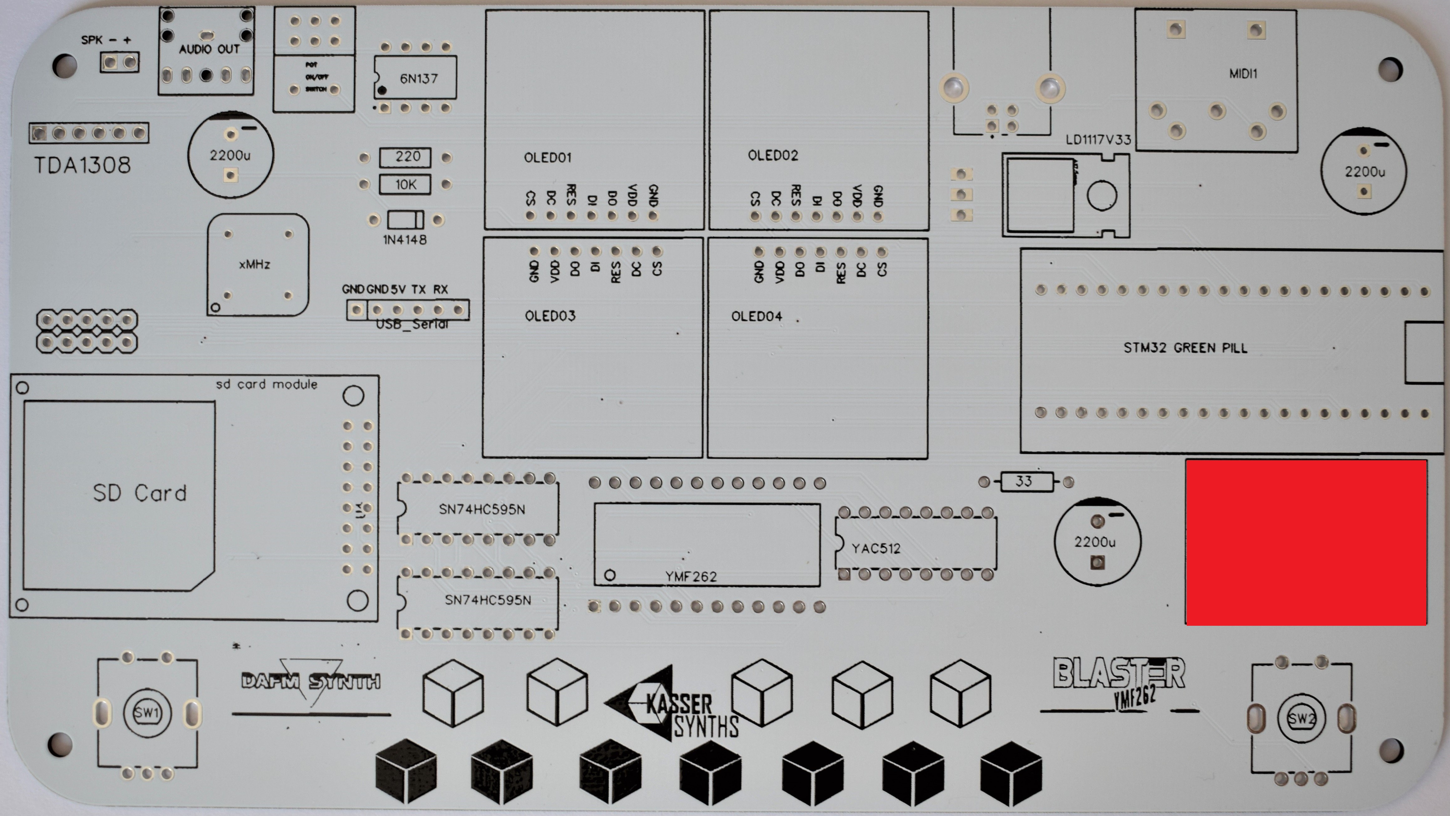
512-key Touch Sensor Breakout
Capacitive touch sensor used for the beautiful tactile keyboard of 12 notes. It can be delivered as a black PCB (MPR121) or as a green PCB (TTP229)
![]()
-
6Rotary encoder with switch x 2
Used to move through the DAFM synth menus.
![]()
-
75V DC Power USB Type B
Female connector for the power supply of the DAFM synth
![]()
-
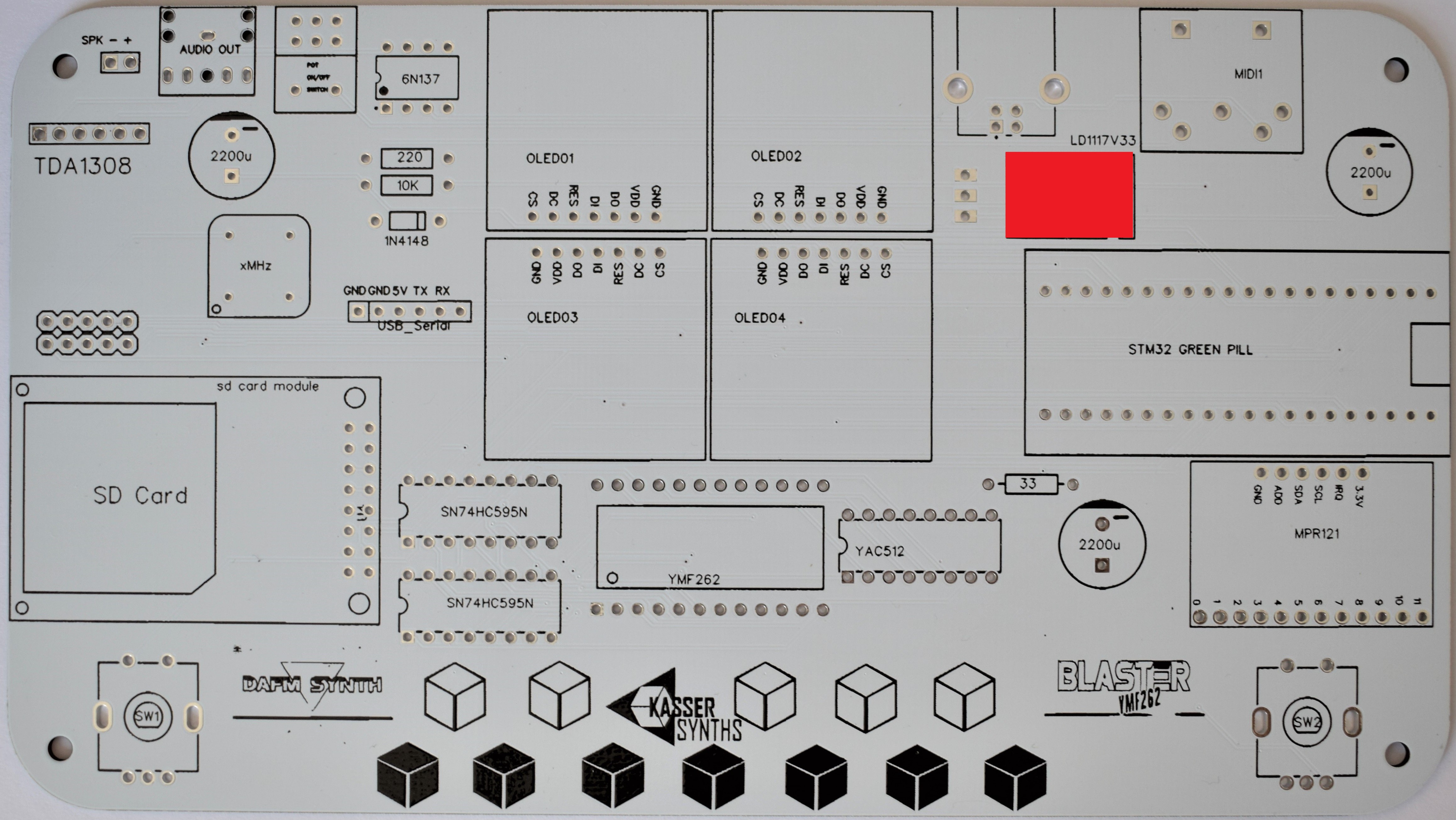
8LD33V Voltage regulator
3.3V voltage regulator for the touch sensor. It’s polarized, but with the legs bent the way they are, there’s really only one way it can go in. Make sure it’s flat against the board before you solder and snip.
![]()
-
9Audio Circuit
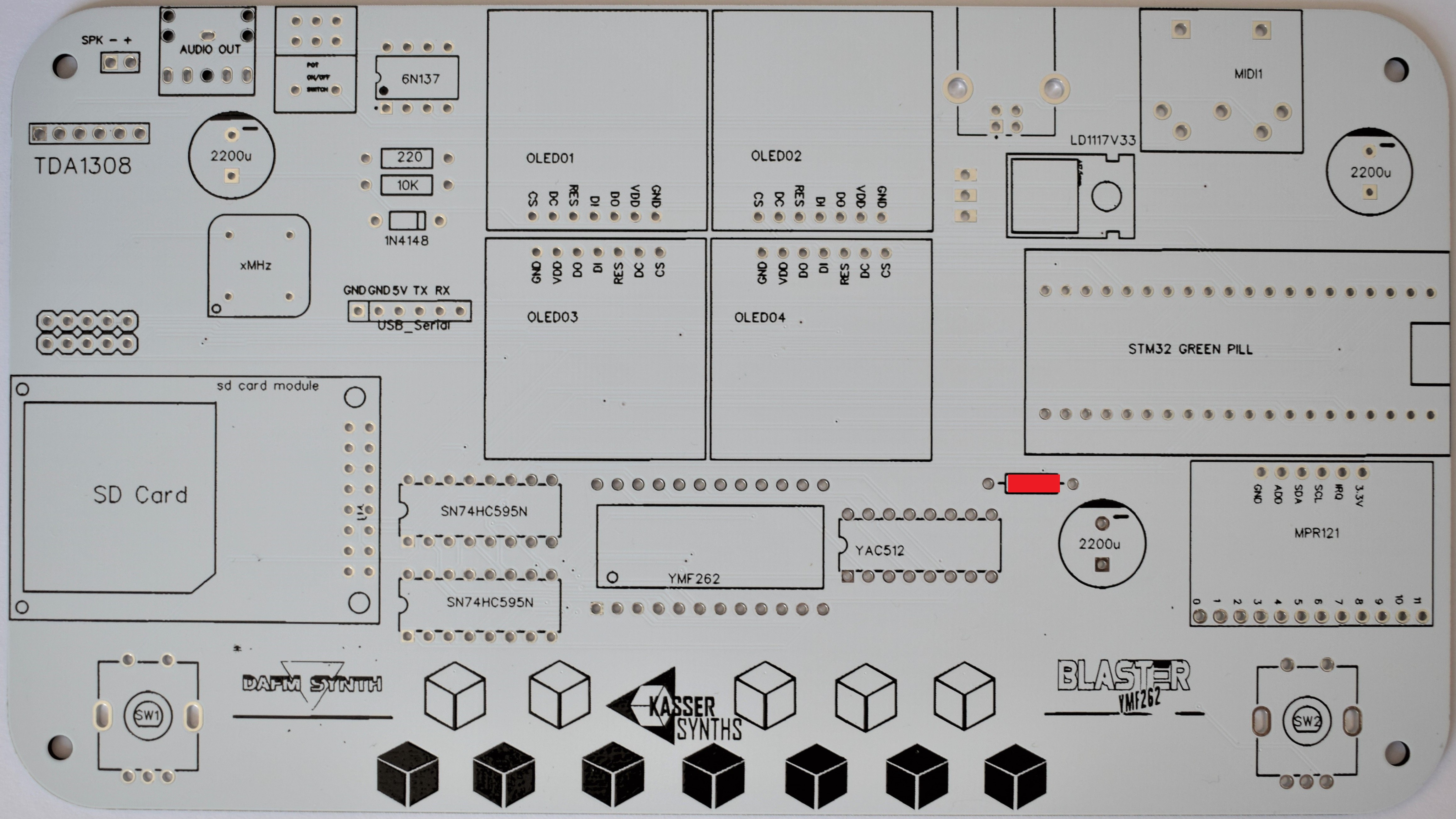
33Ω x 1 (black, orange, orange, black, gold)
This resistor is used in the audio circuit of the YMF262 / YAC512 yamaha chips.
![]()
YMF262 and YAC512 PCB
PCB including the yamaha sound chip YMF262 and its DAC companion (YAC512).
![]()
14.318 MHz crystal oscillator
Clock for the YMF262 chip. The pin on the bottom left with the point corresponds to the pin 1.
It can be delivered as a metallic enclosed through-hole component or as a black PCB with a SMD clock soldered on top.
![]()
⅛” Mini Jack
Audio output for headphones or to connect to an external amp.
![]()
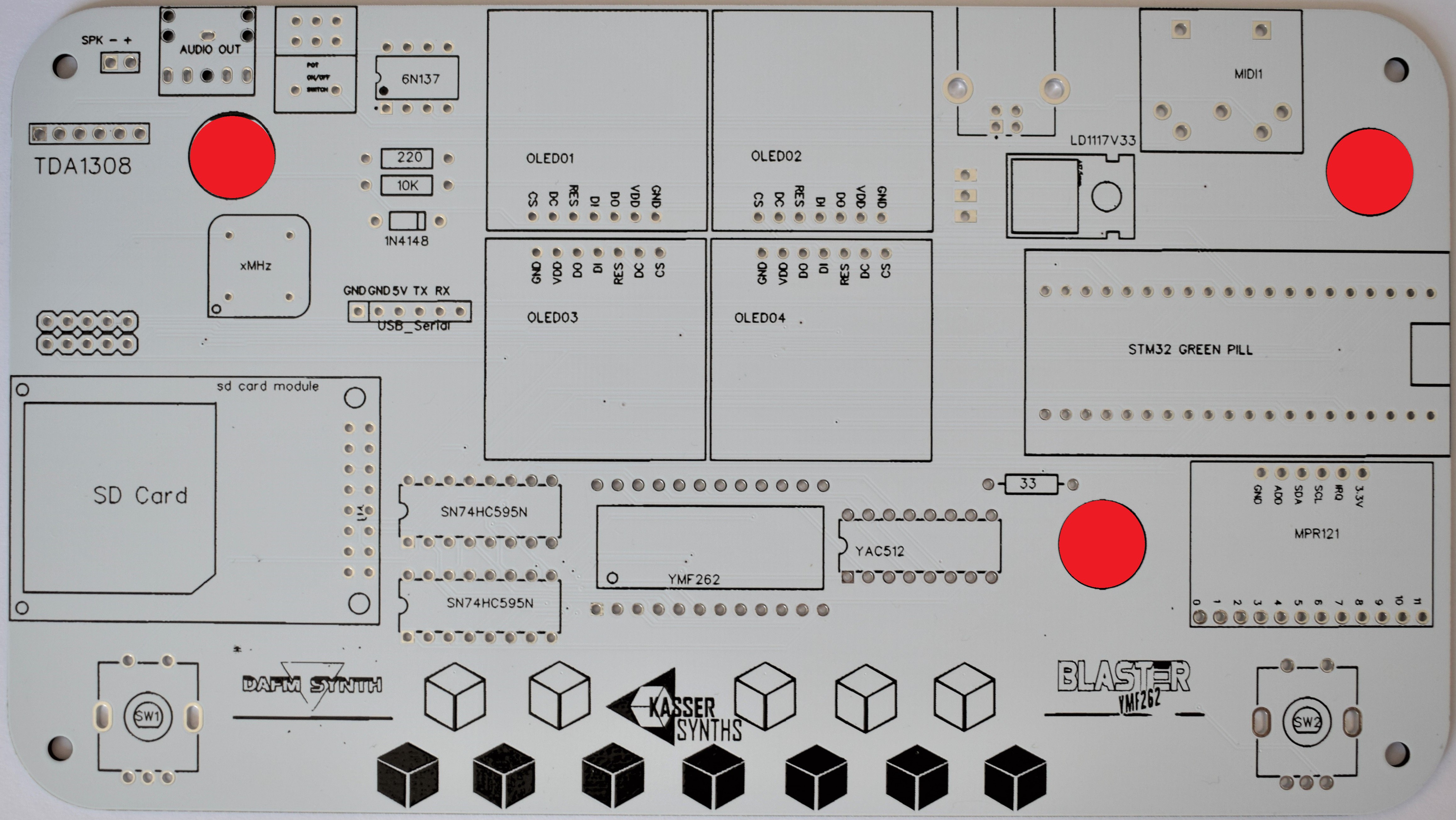
2200 μF Electrolytic Capacitors x 3
Watch out – these are polarized. The white, gray or gold line marked with minuses on the side of the cap indicates ground. On the board, the ground side’s pad is the white part on the side. I usually tack one leg with solder, heat it up and straighten it, then solder the other leg.
![]()
B103 Stereo Potentiometer with switch
Used for turn on / off the DAFM synth and control the audio volume.
![]()
TDA1308 Audio Preamp breakout
Amplify the sound output high enough to use headphones or to connect an external amp.
![]()
-
10Displays and Shift Registers
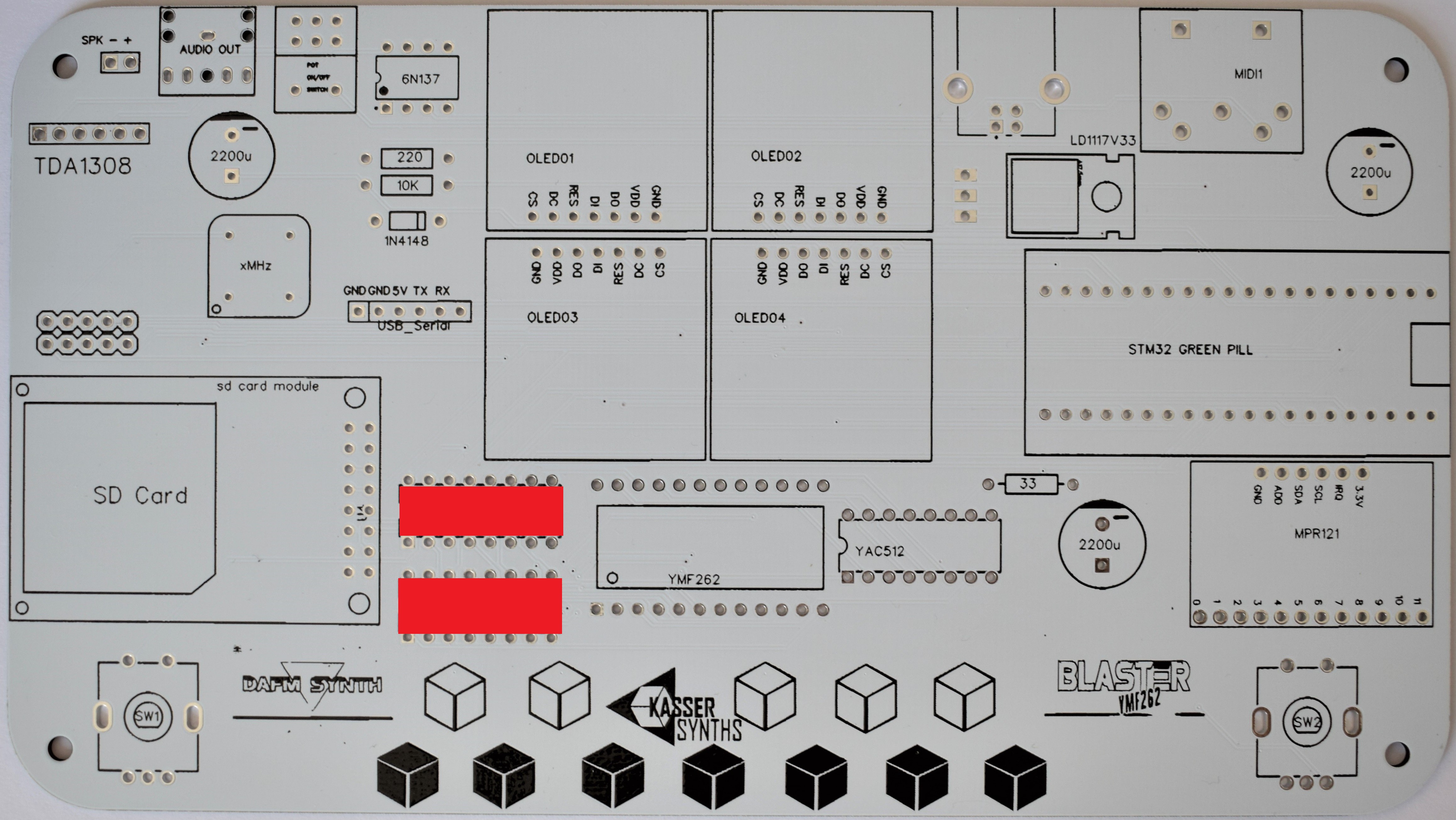
2x IC Socket 16 pins
These sockets are for the 74HC595 shift registers. These IC components expand the digital I/O pins of the microcontroller and allow to control the 8-bit data bus and the function pins of the YMF262 chip.
![]()
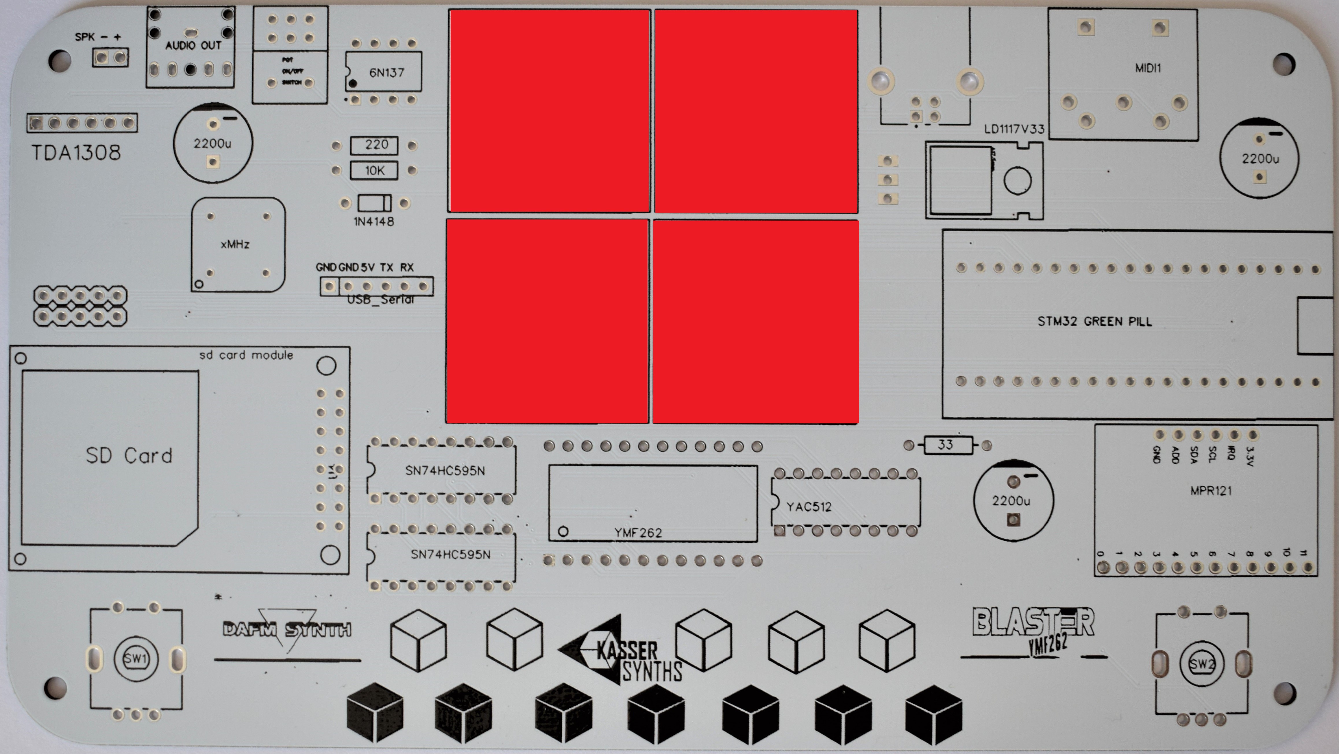
4x 0.96 SPI Monochrome OLED Display breakout
The SPI OLED displays are much faster than the I2C type from the original version. No more MIDI lag during menus diving...!
![]()
DAFM synth BLASTER YMF262 (OPL3) - DIY kit
DAFM Synth is a FM multitimbral synthesizer serie based on mythical YAMAHA chips used for home consoles, arcades and 80s PCs sound.
 KASSER SYNTHS

Discussions
Become a Hackaday.io Member
Create an account to leave a comment. Already have an account? Log In.