-
v2.0
04/11/2022 at 02:07 • 0 commentsHardware release v2.0.
Firmware release v0.1.0.
Working release.
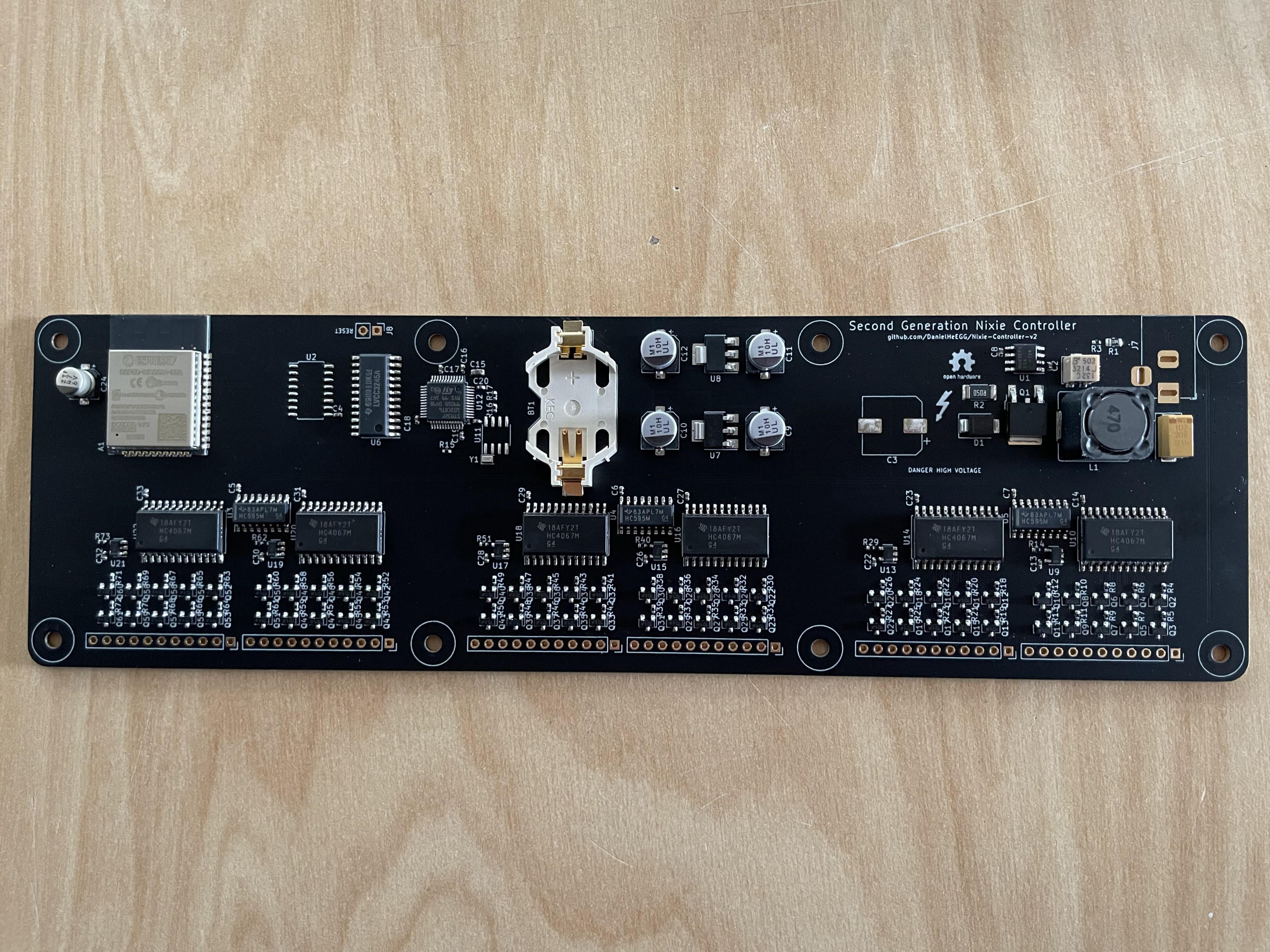
Major Changes:
- Removed indicator LED
- Added reset jumper
- Switched to different ESP WiFi module
- Added test points
![]()
![]()
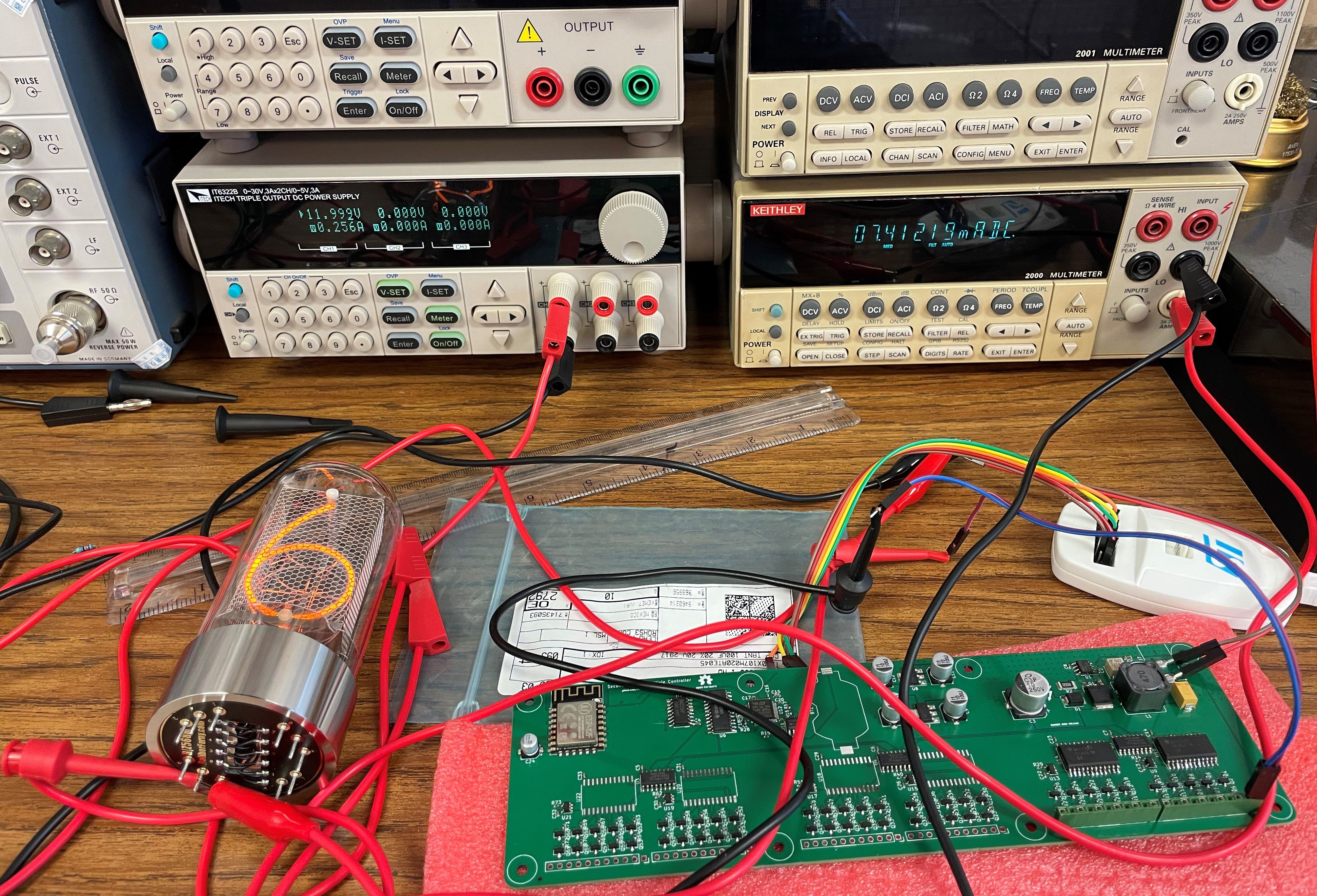
PCB manufactured and assembled by PCBWay. Total cost is $535 for 3 boards, including PCB manufacturing, all component costs, assembly, and shipping.
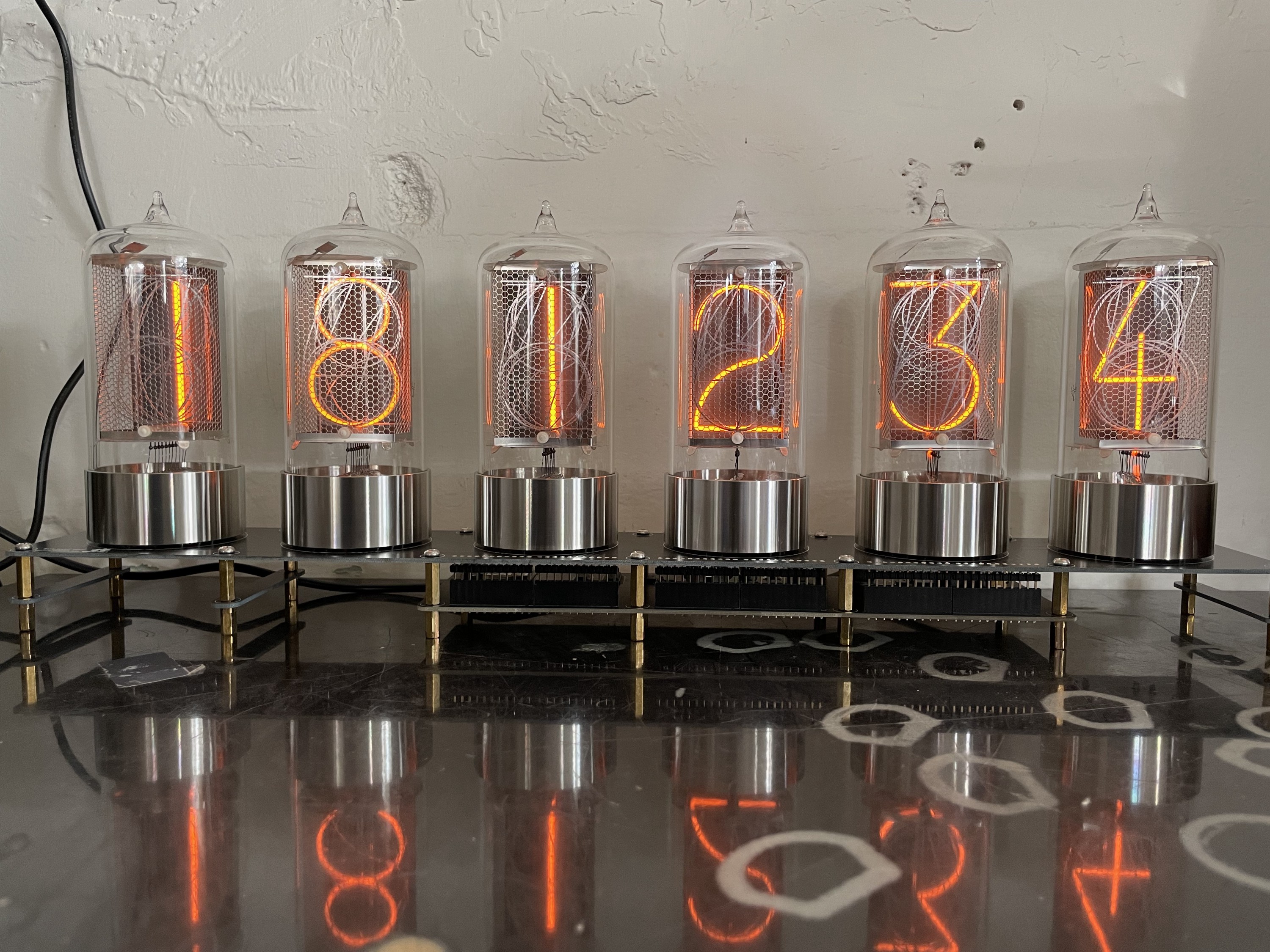
Completed clock in second image uses R|Z568M Nixie tubes by Dalibor Farny.
Planned Improvements:
- Configurable timezones and internet connection
- Switching power supplies for 3.3V and 5V rails
-
v2.0-pre2
11/10/2021 at 21:34 • 0 commentsRelease v2.0-pre2.
Major Changes:
- Fixed BJT footprint
- Added ESP-32 WiFi module
- Shifted microcontroller + relevant circuity to optimize ESP-32 placement
- Removed microcontroller external crystal
- Reduced size of HV supply output capacitor
![]()
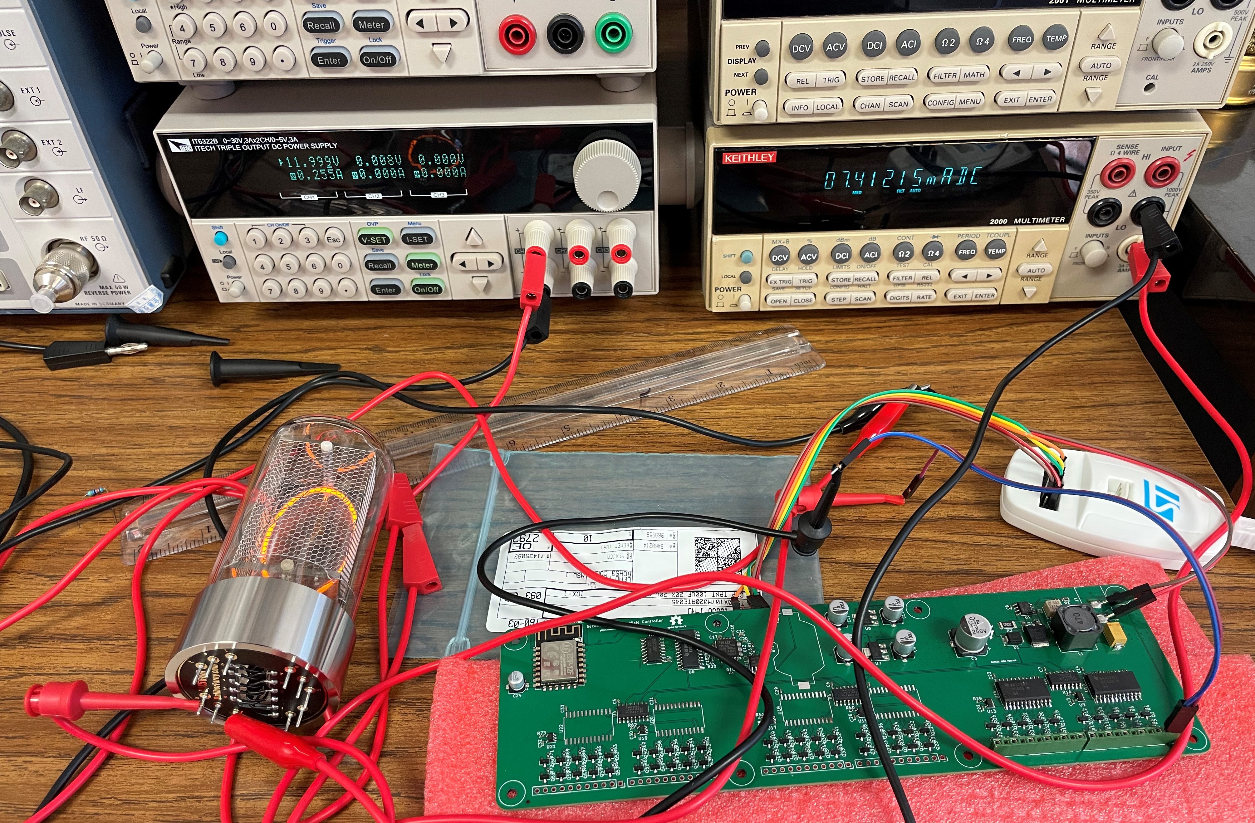
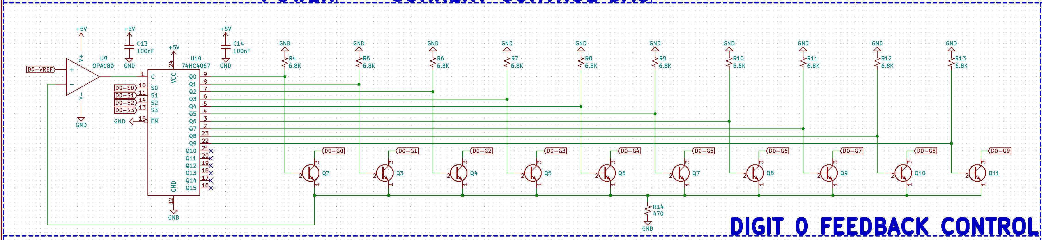
Current feedback loop is fully functional.This allows the controller to work with almost any tube, and have them work at almost any brightness. Especially for larger tubes, this will ensure that all digits remain at the same brightness and reduce uneven cathode poisoning. No external resistors needed.
![]()
![]()
-
v2.0-pre1
11/10/2021 at 21:23 • 0 commentsRelease v2.0-pre1.
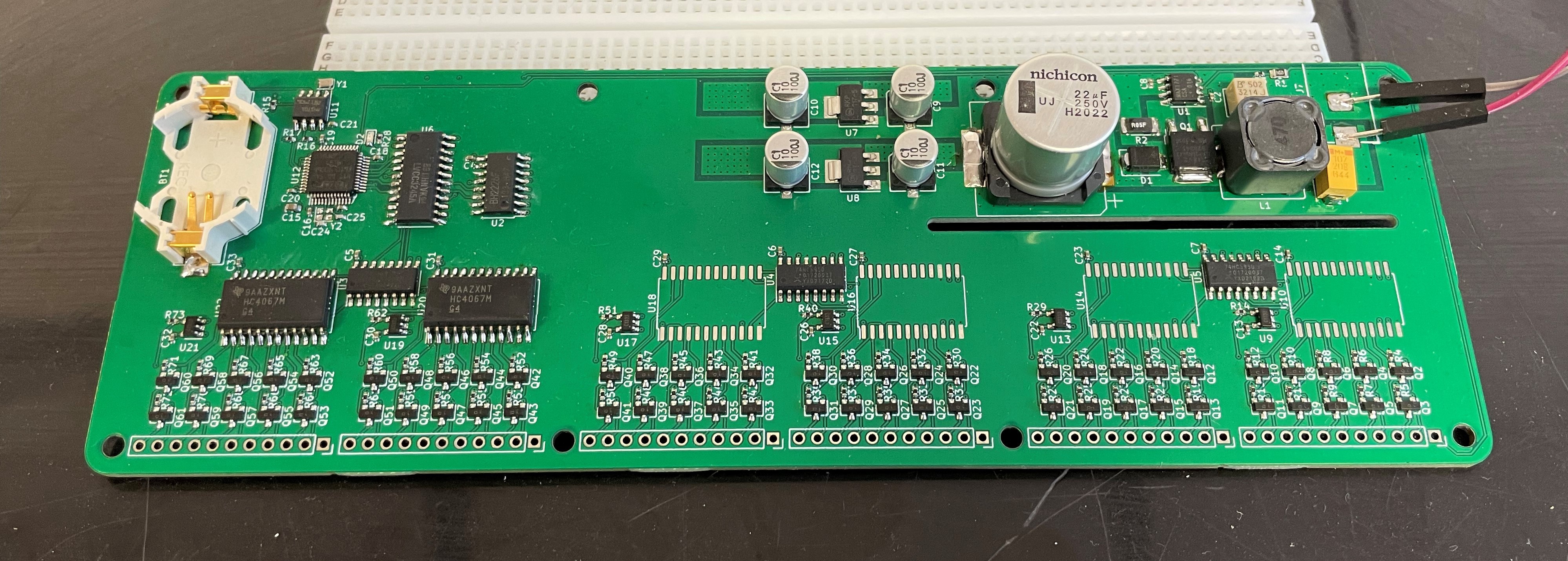
Finalized general board layout.
![]()
Each tube gets its own current feedback loop. Controlled by the shift registers and the DAC. Tube current can be individually adjusted (8-bit DAC) between 0 ~ 10.6 mA.
![]()
What worked:- Power supplies (180V, 5V, 3.3V)
- Microcontroller
- Real time clock
- Level shifter
- DAC
- Shift registers
- Analog multiplexers
What didn't work:
- Current control
I messed up the footprint for the BJTs.
-
Power Supply
10/05/2021 at 23:10 • 0 commentsCommit 98d33ef
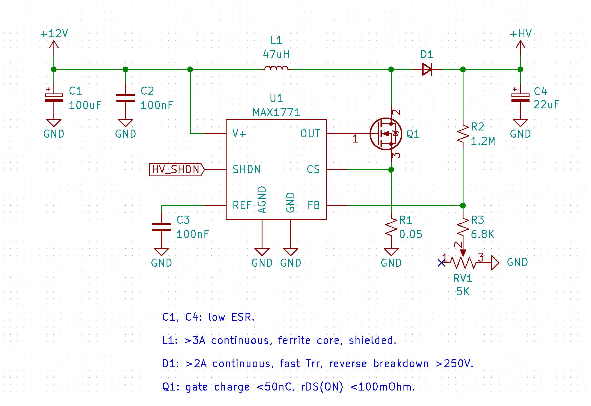
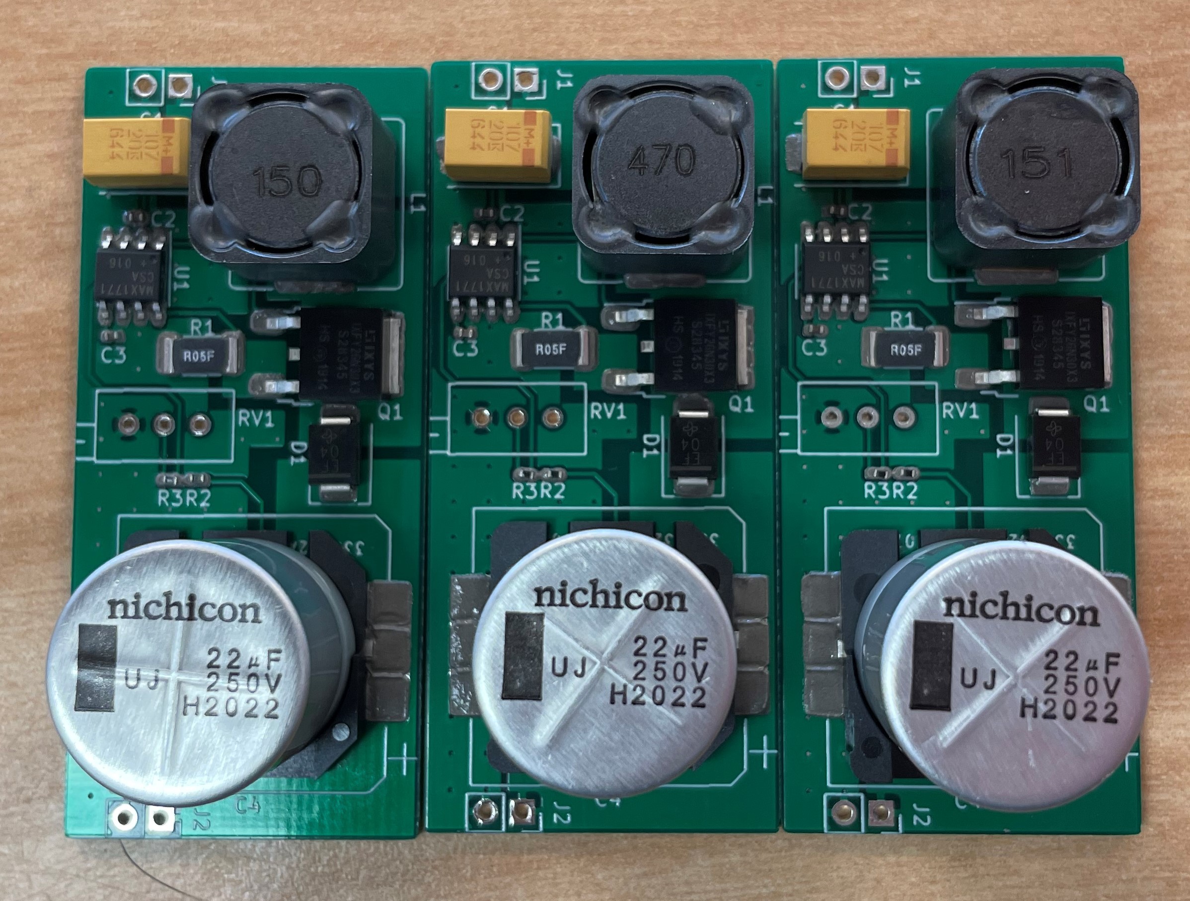
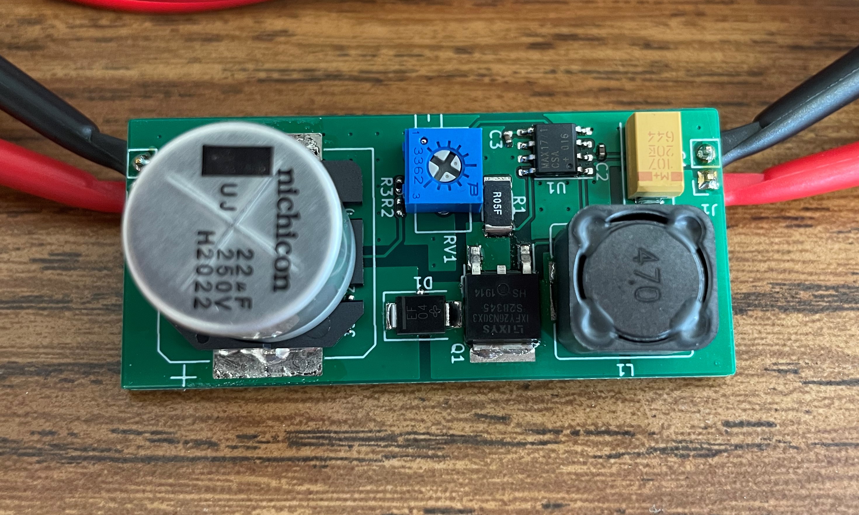
Mostly component optimizations based on v1 power supply design with MAX1771 boost controller.
![]()
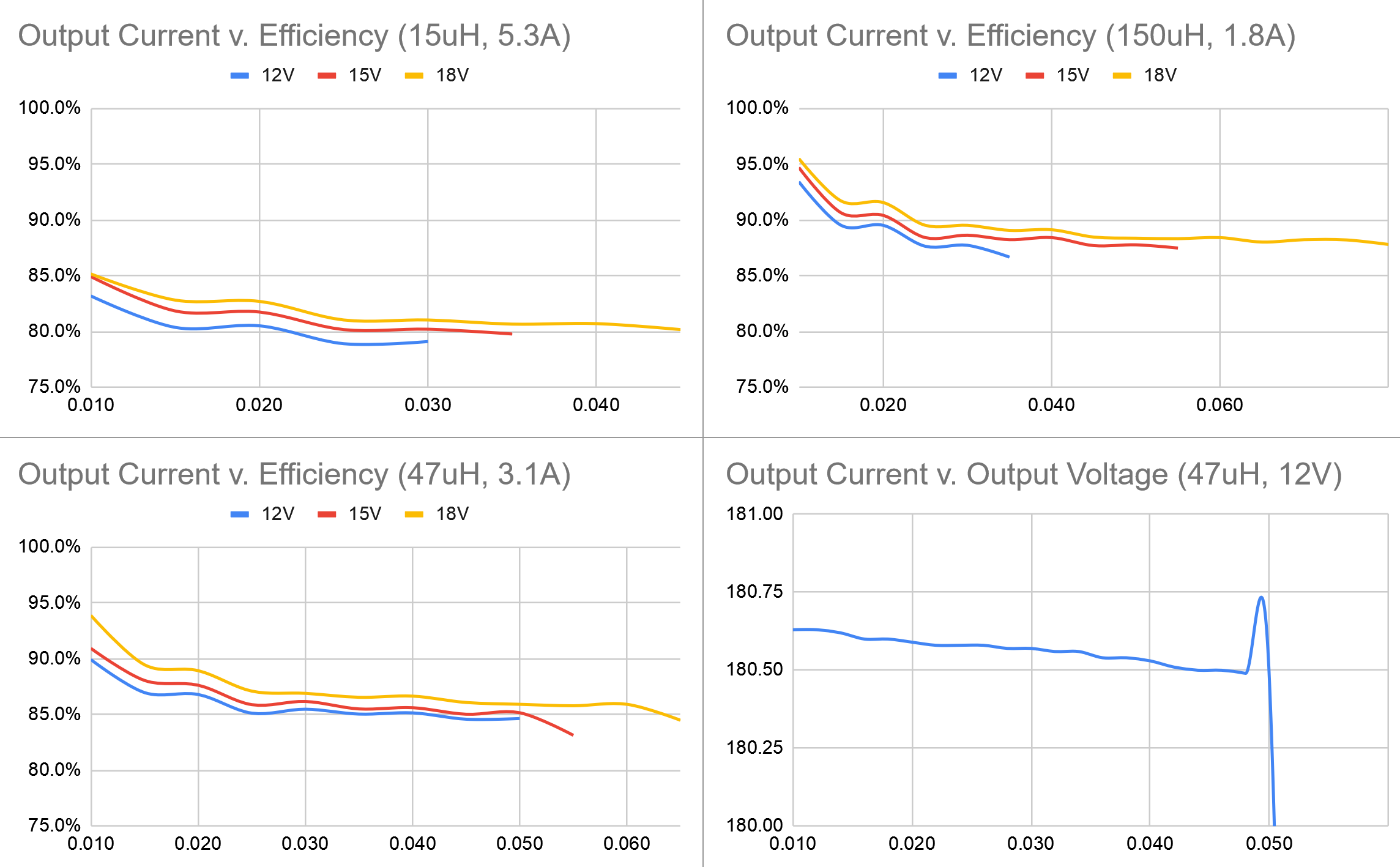
3 different inductor values are tested: 15uH, 47uH, and 150uH. 47uH seems to be the sweet spot for maximum current output @ 12V input.![]()
![]()
![]()
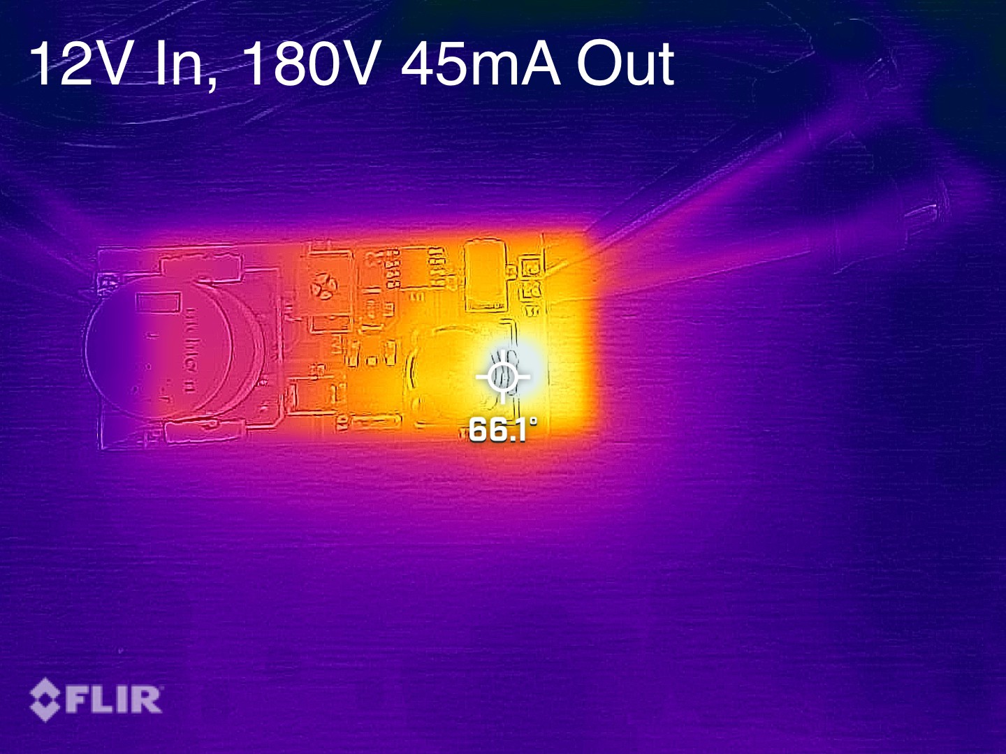
Hottest spot on the power supply reaches thermal equilibrium @ around 65 degrees C.
![]()
Nixie Clock Controller v2
Second generation universal nixie clock controller.