Sergei V. Bogdanov
-
LED and Photodiode holder
10/26/2021 at 12:11 • 0 commentsLEDs emit red, green and blue light to the surface to investigate, and photodiode detects the scattered emission. We have two tasks: LEDs must don't irradiate photodiode, and as much as possible scattered by surface light must be collected by photodiode.
We made some test holders to make a selection. We tested 5 types of holders and select the bes.
![]()
Fig. 1. Scetches of differend LED- Photodiode holders.
![]()
Fig. 2. 3d models of LED-Photodilde holders.
![]() Fig. 3 Slicer picture of LED-Photodilde holders.
Fig. 3 Slicer picture of LED-Photodilde holders. -
Development of a color table for device calibration
10/21/2021 at 23:30 • 0 commentsFor the device to work properly, we must calibrate it, because both the parameters of the LEDs in the WS2812, the magnitude of the supply voltage, and the geometry of the holder of light and photo diodes can differ. Ideally, you need to use a ready-made template (Fig. 1), but we decided to develop a set of colors ourselves and print it on a color printer. To do this, we used a spreadsheet program. In spreadsheets, we can set the RGB color {Red, Green, Blue} of a specific cell (i, j) using the command
Cells(i, j).Interior.Color = RGB(Red; Green; Blue)
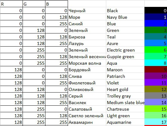
We made two reference color sets - for 27 and 64 colors, respectively for each component from the set {0, 127, 255} and {0, 85, 170, 255}. An example is shown in Fig. 2.
![]()
Fig.1 Etalone color set
![]()
Fig.2 Self-made color set
-
LED - PhotoDiode Block
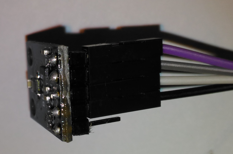
10/16/2021 at 14:48 • 0 commentsWe use GY-302 I2C light detector. We got it with pins, but we don't need pins. We solder thin maylar isolated wires.
Fig. 2.01 Light detector GY-302 (BH-1750 chip).
We made box for GY-302 and RGB LED WS2812
Fig.2.02 Box for LED and GY-302.
Fig. 2.03 Box with LED and GY-302.
Now we can make som experiments with color.
-
Set up of components
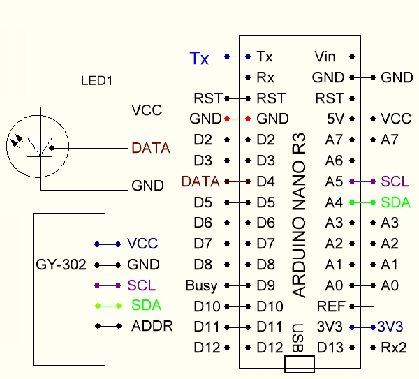
09/27/2021 at 23:37 • 0 commentsWe deside to cotstruct device to help visually impared people to identify colors. It is useful for washed socks sorting and for clothing combinations. We decide to find some schematics for color determination. The simplest way we think is to use adressable RGB LED WS2812 and chip light detector breakboard GY-302.
Fig. 1 Schematist of color deteciton test.
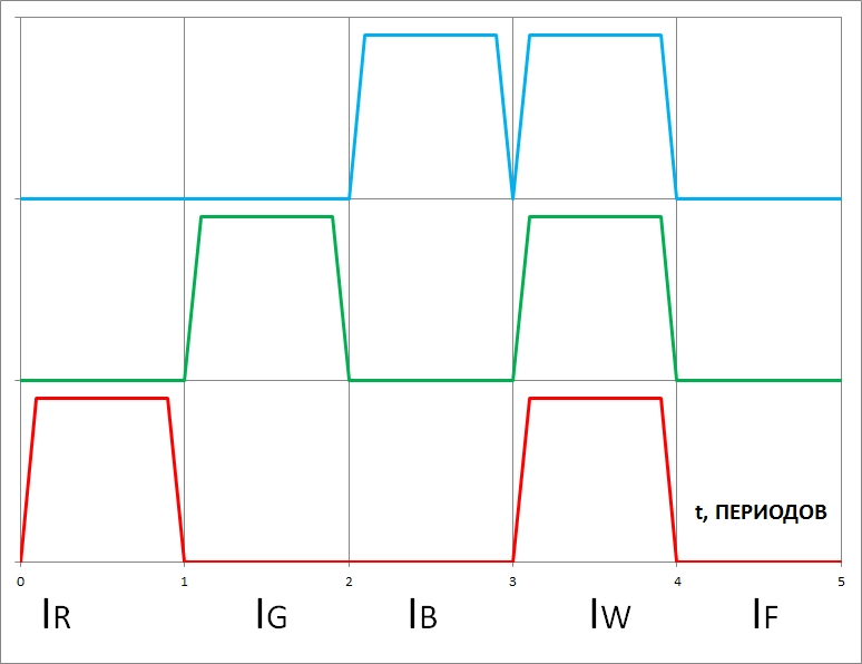
PCB Arduino control LED. LED emits red light (firxt cycle), and Green, Blue, all 3 colors and no color (Fig.2)
Fig.2 5 cycles of color determination.
We applied the method of recording the reflected signal by successively illuminating the object with three colors - red, green and blue, as well as three colors simultaneously, and then with all the LEDs off (measuring the background level). A photosensor with a digital interface registers 5 values - for 3 components IR, IG, IB, common when illuminated with all 3 colors IW and background IF when all illumination LEDs are off. The timing diagram is shown in Fig. 2. The received data is processed by the microcontroller - it calculates the sum of the IRGB components:
IRGB = IR + IG + IB (1)
This value is compared with the signal when all LEDs IW2 are on, and if the relative difference is greater than a certain threshold ε
ε <| IF - IR - IG - IB | / (IR + IG + IB) (2)
then the measurement result will be rejected, the device reports "Color not detected". This is the criterion for the correct operation of the measurement logic. Also, the result will be rejected if the background illumination IF exceeds a certain relative (in IRGB fractions) threshold δ δ <IF / (IR + IG + IB) (3).We made some tests and decide to use this method of color determination.
Сolor Identifier for visually impaired people
Color Identifier can identify the color of clothes (and other household), tell the color and what other colors is compartible with this one.
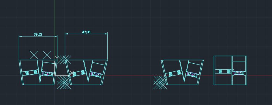
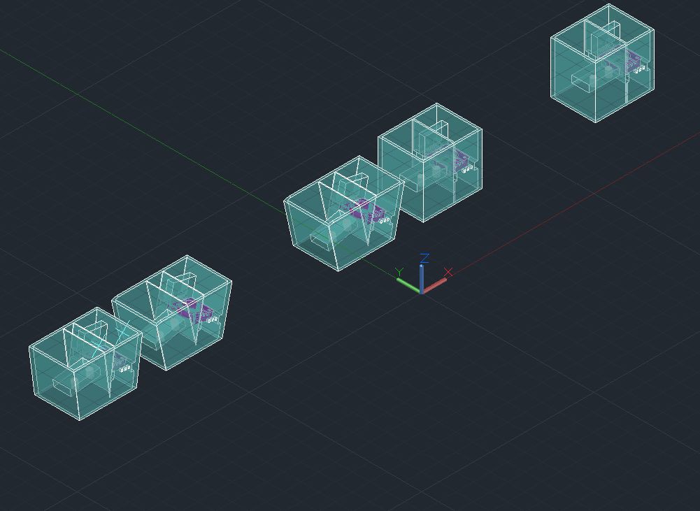
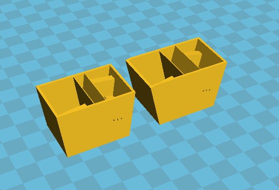 Fig. 3 Slicer picture of LED-Photodilde holders.