HP 28S LiPo Battery
My attempt at a non-destructive LiPo retrofit for the unique-yet-somewhat-loathed HP 28S calculator
My attempt at a non-destructive LiPo retrofit for the unique-yet-somewhat-loathed HP 28S calculator
To make the experience fit your profile, pick a username and tell us what interests you.
We found and based on your interests.
HP28S_battery.kicad_pcbVersion 1.1 PCB design file (KiCAD)kicad_pcb - 37.64 kB - 10/14/2021 at 15:49 |
|
|
HP28S_battery-Schematic_1v1.pdfVersion 1.1 schematic (PDF)Adobe Portable Document Format - 25.54 kB - 10/14/2021 at 15:43 |
|
|
HP28S_battery.schVersion 1.1 schematic (KiCAD)sch - 8.90 kB - 10/14/2021 at 15:42 |
|
|
HP28S_pcb_holder_1v0.3mf3D model of PCB holder sled3mf - 5.47 kB - 10/14/2021 at 15:36 |
|
|
HP28S_pcb_holder_1v0.scadPCB holder 'sled' (OpenSCAD)scad - 1.91 kB - 10/14/2021 at 15:36 |
|
|
I received my PCB from OSHpark earlier in the week, and finally had a chance to populate them. I already had parts on hand from my prior calculator battery pack exploits, so I didn't have to worry about component shortages. No issues with the build, and it mated perfectly with one of the two 3D printed PCB holders I had made for the occasion.
A better view showing off the PCB holder and the clearance for the USB solder blobs and end terminal
To prep the HP28S for battery upgrade, I first had to prep the LiPo battery for its new home. I did this by removing the positive wire, and soldering on a much longer wire (too long, in fact - it really only needs to be about 8cm long) and then placing some "EMC tape" over the positive end of the battery. This makes that entire end of the cylindrical battery positive, so as to make contact with the HP28S positive spring terminal. Similarly, I tacked on a longer negative battery lead, which really only needed to be about 5cm long in hindsight. I'll take a photo of the next battery that I prep and post it in a subsequent log.
The HP28S battery cavities have some foam tape stuck in there, presumably to keep the N cells from rattling around. The 13450 LiPo battery is a very tight fit so this foam has to go. After removing the foam, I used a 1/2 inch drill bit to very carefully enlarge (more like: 'scraped') the cavity. Even still, for this particular calculator, the 13450 LiPo cell is in there so snugly it's probably a "one-way trip".
I had already charged the LiPo cell for a few hours, until the charge LED extinguished, so I knew the PCB was working well. I then stuffed the LiPo cell into the upper cavity and placed the PCB and holder into the lower cavity. The PCB and holder seemed to "grab" something in there and stayed put pretty well.
(You can see the too-long wires here, which I will correct) After inserting the LiPo and the PCB+holder, I was rewarded with a working calculator. This at least gives me some hope that using a castellated edge along the PCB serves as a nice means to provide negative contact to the calculator. The large buffer capacitor inside the HP28S will certainly go a long ways towards mitigating supply dropouts due to contact bounce.
I updated the KiCAD PCB and KiCAD and PDF schematic files to reflect that R1 should be changed from 4.7K to 10K to set the LiPo charging current at 100mA.
I cleaned up some copy-paste error on the PCB title block text, and bumped the date and version on both the PCB and Schematic design files.
In order to keep the PCB in place inside the HP28S, I designed a simple "sled" like object to which the PCB attaches. The idea is to provide a rounded base that will keep the PCB centered across the cylinder-like shaped cavity in the calculator where the single N cell and the HP28S's negative terminal normally reside.
I love OpenSCAD, especially for things like this that are pretty easy to describe procedurally.
I made the holder shorter in length than the PCB to allow for the PTH solder blobs under the USB connector, and to allow the negative "terminal" of my PCB to engage with the HP28S negative contact spring. I like to include a "model" of the PCB in OpenSCAD, also - I suspect that there's some clever way to take 3D render info from KiCAD into OpenSCAD somehow, but my mechanical CAD foo just isn't that mighty. So, I just include a cube of the appropriate size, translate it to the correct spot in the assembly, and color it green:
The idea is that the holder is merely meant to keep the PCB into roughly the correct position so it stays in contact with the HP28S negative battery spring terminal.
The HP 28S is a nice calculator, but the battery solution is awful. I have made modern battery solutions for my HP Classic and Texas Instruments TI-59 calculators, which has given them new life. Can I do something similar for the HP 28S? because it really needs help in this department!
My inspiration came when I confiscated two e-cigarettes from a teen's bedroom earlier this year - but that's another story. After smashing the e-cigs to bits, I noticed that each had a cylindrical LiPo cell inside. I set them aside, thinking that at some point I'd have a use for them...
Fast forward a few months, and rediscovering my HP 28S calculator with its mangled battery cover. Hmmm.. I wonder if one of those scavenged LiPo cells would fit inside? Will the calculator work from one 3.7V cell? Could charging circuitry somehow be included?
Answers: "sort of", "yes", and "probably".
Here's my sloppy sketch of the idea:
The HP 28S has three N cells - all are in series, but there are two "tubes" side by side - upper tube holds two cells, and the lower holds only one. The inside end of the upper tube is where the positive contact lives, and the inside end of the lower is where you find the negative contact. The battery retention cover provides the "short" between the cells in the two tubes.
Each N cell is (approx) 12mm diameter x 28mm long. The scavenged e-cig LiPo is type EVE13450, which is (approx) 13mm diameter and 45mm long. It's a bit tight, but the 13mm cell just fits into the upper tube - my calculator has a strip of foam inside the upper tube that I might have to remove to make it fit the LiPo better.
The LiPo is approx 680mAh, which is a bit shy of the 800-1000mAh that Alkaline N cells provide, but better than the 500mAh that NiMh N cells offer. So long as it's easy to recharge, I don't see an issue with the slightly diminished capacity. The three N cells in series provide 4.5V, whereas the single LiPo cell provides 3.7V. The discharge curve of the LiPo is better, however; the 3.7V is pretty constant for most of the charge life. My tests have shown the HP 28S works from a 3.3V power supply very well so, again, no issue expected here.
Some sort of metal "stuff" is needed to bring the LiPo positive wire in contact with the metal contact spring inside the calculator - some metal foil taped to the end of the LiPo cell, for example, would probably work here.
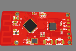
The USB charger circuitry should live in the shorter lower tube. This is also where the calculator's negative terminal is, so contact needs to be made to that as well. Therefore, both LiPo positive and negative need to go to this PCB via some small wires. I think a small 3D printed "holder" or "base" might be needed to snugly locate the PCB into the lower tube and keep it in place when the USB cable is plugged-unplugged. The circuitry is trivial, exactly the same as that of my first HP Classic LiPo retrofit. The "ideal diode" is not required here, because the calculator will never see more than the single LiPo cell voltage (about 4V during charging - still under the 4.5V of three fresh N cells in series). I designed a PCB that is 12mm wide and 26mm long, with a negative contact castellated along the "inside" end of the PCB to make contact with the calculator's negative terminal spring. All together, the PCB looks like this:
The "POS" and "NEG" pads are for connection to the LiPo terminals. I left the soldermask off the inside end of the PCB in case my castellated end doesn't work and I need to attach some other sort of contact.
In theory, the only pressure on the battery retention lid will be the USB connector pushing against the inside of it, and I made the PCB 26mm long vs. the 28mm long N cell, so that should reduce the spring tension as well.
Create an account to leave a comment. Already have an account? Log In.
It may be quite a while. As long as I am buying new, name brand, batteries, the N cells last 2 or 3 years.
That’s a robust solution to the awful design problem that this otherwise wonderful calculator suffers from.
I would think that a carefully positioned hole on the rear case, and a matching tab on the metal plate would stop the “flow” of the plate.
It would fix the flow problem, but finding a non-destructive location for a hole would be hard on the calculator. The article I saw a while ago said the cases are heat sealed. The flow problem is easy to deal with and only needs messing with occasionally as it is.
excellent point, and you have to remove the plate to replace batteries periodically, anyhow, I suppose.
I like the calculator LIPO battery pack projects that you have been working on.
Here is my solution to the HP28S broken battery door problem: #HP28S Battery Door Prosthetic
Become a member to follow this project and never miss any updates
By using our website and services, you expressly agree to the placement of our performance, functionality, and advertising cookies. Learn More

 Sagar 001

 CYUL
CYUL
 UltraReidar
I’ve been running the “repeating self-test” to see how long a charge lasts. So far more than 48 hrs, but I have no idea how long the same test can run on a fresh set of N cells.
Anyone ever done this, by chance? I can access the positive and negative terminals in my 28S and do the N cell test after the LiPo discharges. But I have no idea how long that will be…