In one of my previous videos, I described how to make a cheap Advanced Barometer, used by sailors, yachtsmen, etc. It is a great weather forecasting device but still requires some knowledge in the field of meteorology.
This time I will show you how to make a Zambreti weather forecaster, which displays the weather forecast on the screen in the form of descriptive text.
It contains a total of 26 reports that describe in detail the weather forecast. The original Zambretti Forecaster was developed in 1915 by precision instrument makers Negretti and Zambra. It was a hand-held disc calculator, that provided on-demand short-term forecasts of up to 12 hours. It consists of 3 plastic discs of descending radius, arranged concentrically and secured together by means of a rivet. The large outside disc A has a short scale calibrated in wind direction, the middle disc B, has an index to be aligned appropriately with the wind direction scale on A, and itself carries a scale calibrated in units of barometric pressure (inches of mercury or millibars). The inner disc C has an index settable to the atmospheric pressure on B and three windows which allow the selection of a reading based upon of the rising or falling of the barometer in Winter or Summer. Through the appropriate window, an alphabetic letter is visible ( printed on disc A) and this letter is the key to the forecast which can be read off on the obverse side of the instrument. It is reported that the forecasts are most accurate when generated at 9.00 am local time. The calculator uses the mean sea level pressure (MSLP) and pressure trend (steady, rising or falling) as the primary input. The season (Summer or Winter) and the wind play a minor role in determining the forecast.
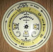
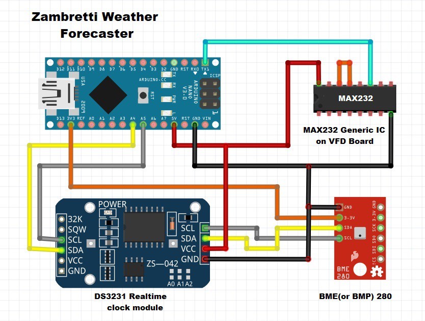
This device was an electronic version of this calculator that automatically generates reports on the display. It is very simple to make and consists of several components:
- Arduino Nano microcontroller
- 20x2 VFD display from old POS Terminal
- DS3231 Real time clock module
- and BME or BMP280 sensor board
Also in one of my previous videos I showed you how to control an unknown VFD display via a tx-rx connection with Arduino. (see the video below)
DS3231 Realtime clock module serves only to determine the season (winter or summer). Of course with very small changes in the code this device can be made with a 16x2 LCD display which is much easier to control. As a basis, I used Fandonov's code for an e-paper weather station (https://github.com/fandonov/weatherstation/)
Immediately after switching on, a short time report and the current value of the Relative Atmospheric Pressure appear on the screen. This weather report is based on momentary pressure and is not realistic. The first realistic weather report appears after one hundred minutes and is updated every 10 minutes. The current Relative Atmospheric Pressure is displayed in the lower right corner and is updated every minute. There are a total of 26 weather forecasts that describe in detail what the weather will be like in the next 12 hours:
1. Settled Fine
2. Fine Weather
3. Becoming Fine
4. Fine Becoming Less Settled
5. Fine, Possibly showers
6. Fairly Fine, Improving
7. Fairly Fine, Possibly showers, early
8. Fairly Fine Showery Later
9. Showery Early, Improving
10. Changeable Mending
11. Fairly Fine , Showers likely
12. Rather Unsettled Clearing Later
13. Unsettled, Probably Improving
14. Showery Bright Intervals
15. Showery Becoming more unsettled
16. Changeable some rain
17. Unsettled, short fine Intervals
18. Unsettled, Rain later
19. Unsettled, rain at times
20....
 mircemk
 Timo Birnschein
 Chris B
I was inspired by your efforts -- bought a display like yours. Mine, however, is very different inside. It's an IBM job, FRU 41K6814 -- and it's RS485 :( 4pin strange telephone-like connector (FWIW: I'm in the USA) with side-clips to hold it in.
*However*, the PCB also has an unpopulated 10pin footprint for what looks to be a pin header in a shroud. Pin 1 is GND, Pins 2 and 10 are +5v, and Pins 3,5,7 are signal pins; Pin 3 and Pin 7 are common. Further, there are PTH test points (yup, plated through-holes you can solder to as test points!) for +5v +12v GND and signals labeled "EBB" and "EK". Only the supply pins are common amongst all three connectors.
The microcontroller, annoyingly, is either an ASIC or a custom silkscreen job -- it is marked solely with an untraceable IBM part number. It's a QFP44 with power on Pin 38 and 42,43,44, and GND on Pins 16,17 if that's at all helpful.
The signals on Pins3,5,7 of the 10pin connector go to Pins 4 and 3 on the microcontroller. I can't immediately tell what pins go to the RS485 circuitry or to "EBB" and "EK".
RS485 signaling is via an SN176B (marked A176B) and, immediately prior, a 74LS86A. Other notable chips are a Toshiba TD62C950RF shift register and a pair of TI SN755700A chips which seem to be VFD-and-similar-display HV driver chips.
So, if I may ask -- from this info, can you tell if maybe there's an RS-232 or TTL-serial signal option here? I know these displays were available in either configuration...
Message me if you want photos or need to ask questions.