Close
0%
0%

Commodore 64 Diagnostic Dongle

Instead of making FIVE different dongles for C64 diagnostics, I'm just going to make ONE

Similar projects worth following
In the past, to run the C64 diagnostics to verify all the inputs and outputs are working correctly, Commodore provided a diagnostic software to run, and provided details on how to build a huge loopback cable. Over the years, this has gotten simplified. Now you can buy 4 circuit boards and a cable adapter to get the job done. Now I want to design one board to do everything.

The C64 has five ports to test:

  • User port
  • Cassette port
  • Serial port
  • Control ports (2)
  • Keyboard port

There two control ports, but I'm going to count this as one since they are right next to each other.

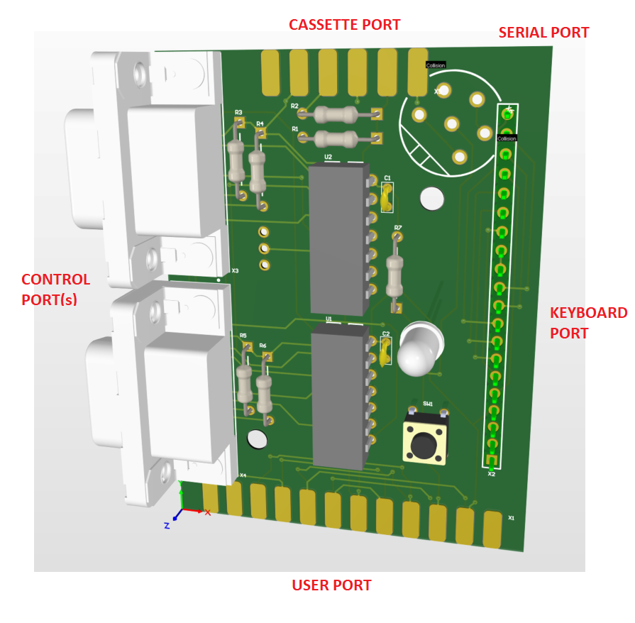
The keyboard port, user port, and serial port just requires simple loop back wires.  The cassette port has two resistors.  The control ports are a little more complicated.  They have two resistors for each of the two ports.  But the joystick pins feed through 4066 analog switches.  And the switches are controlled by the WRITE pin on the cassette port.  One wire is required to go from the cassette port to the control port.

Some designs have all the logic on one board with cables running from every other port.  Some designs have a separate PCB for each port.  I was originally going to order this.  There's shared files on PCBWay for $5 each.  You'll get 5 of each board and you'll need 4 different designs.  And you can't get the serial port adapter from them.  So that's $20 worth of boards and you'll get 5 times as many as you need.

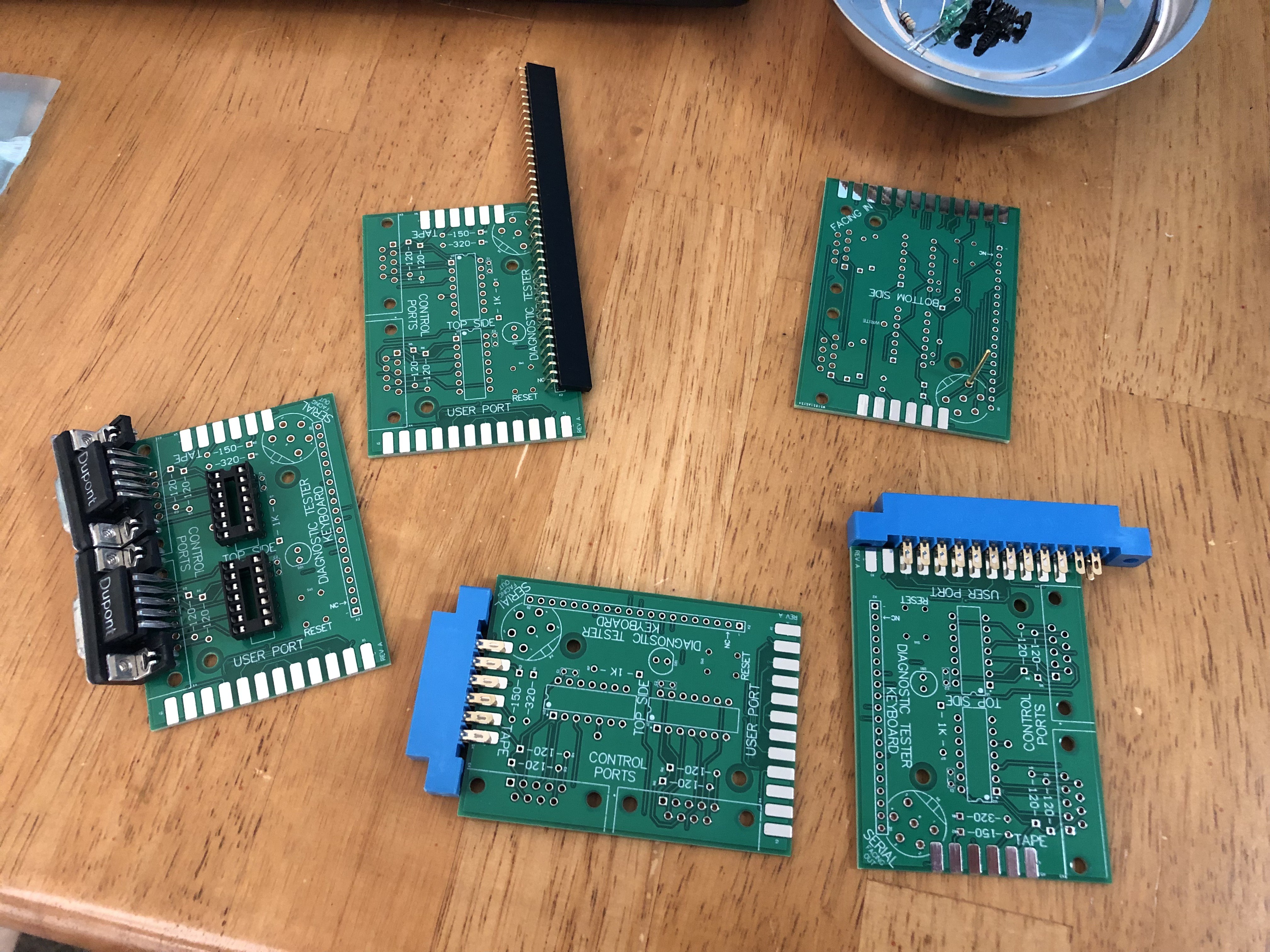
Since minimum quantity is 5, how about I design one board with 5 different assembly options.  Then it's just $5 and I get 5 boards - just right!

There's a few other configurations - the C128 requires a different keyboard connector.  Also, this doesn't include the cartridge PCB to put the software ROM on.  But I don't really mind getting a few extra PCBs for cartridges.  I can use 5 cartridge PCBs.
  • Couple more errors

    Justin Davis11/19/2021 at 18:07 0 comments

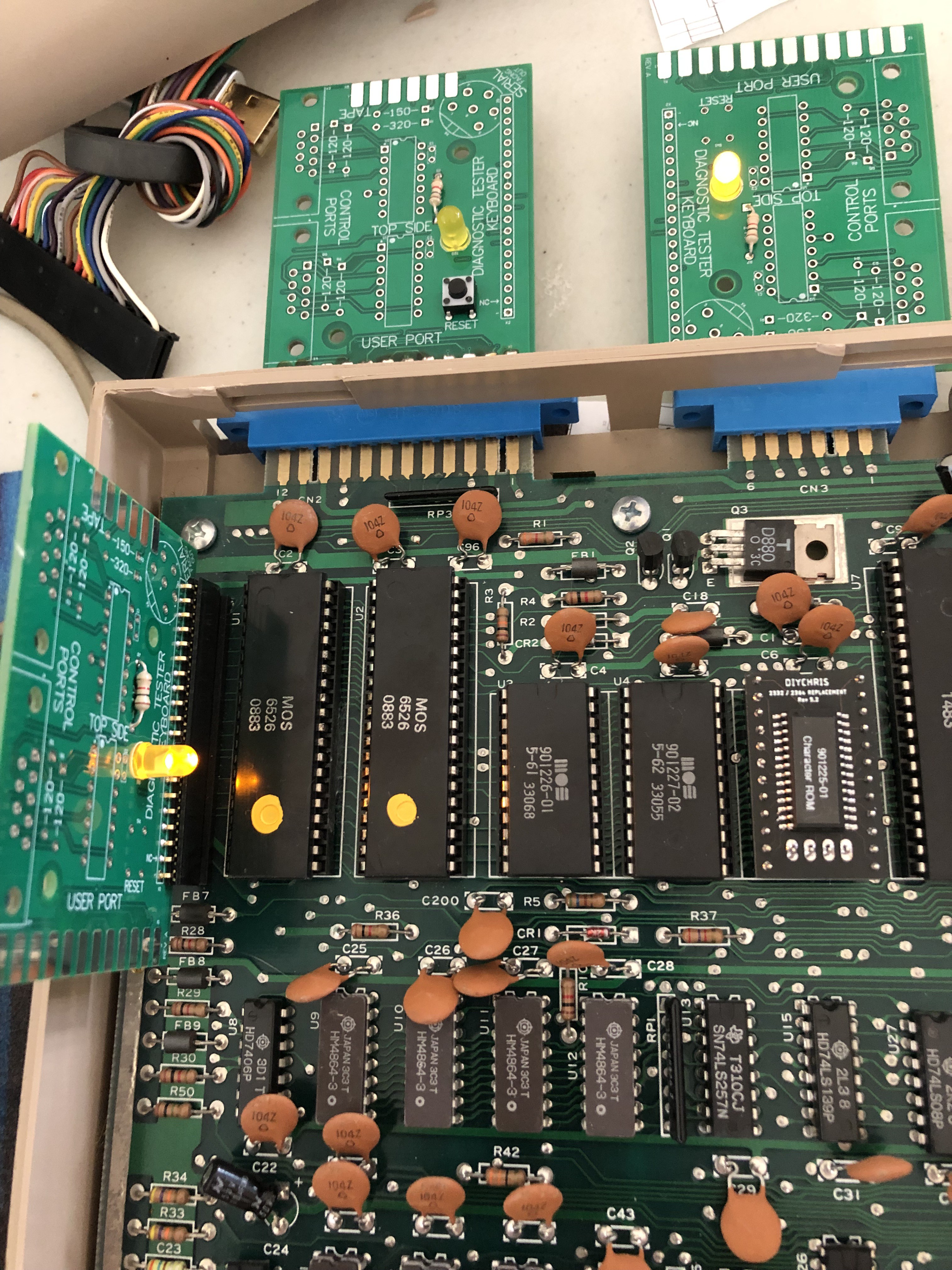
    The whole reason I started this was because I had bought a faulty C64 and was trying to fix it.  The last component which I think is bad just came in - a replacement SID chip.  It appears to be working, so I can read the paddle inputs now.  When I tested the paddle inputs, I found the paddle resistors on my board are supposed to be 120K and not 120 as are on the board now.  I need to replace and test again.  I think with the serial port I'll just stick a couple solid core wires in as jumpers just to pass the test for now.  And then when everything is working I will update the gerbers on PCBWay.

  • Parts are in

    Justin Davis11/12/2021 at 20:15 0 comments

    I finally got all my parts.  I was able to test everything, but ran into some problems.  When I plugged the control board in, the power supply dropped out.  Turns out I used the wrong footprint for the female DB-9 connectors.  I must have use the male DB-9 footprint because the pinout is reversed.  I will remove the connectors, and solder them upside-down instead.  That should fix that problem at least in the short term.

    I also tried to solder the pins in for the serial connector.  I ran into trouble here as well.  Turns out I used a 9mm circle instead of a 7mm circle.  I was never 100% on the dimensions for that connector.  So the pins don't fit in the computer connector.  Kind of disappointing.  I will update the layout.  I'll have to decide if I want to make a new set of boards or not.  But I need to finish proving out the rest of the design first.

  • Assembly - 2 down

    Justin Davis11/05/2021 at 15:28 0 comments

    I got the user board and the keyboard dongle finished, and the tape board about half done when I ran out of solder.  I don't think in my 20 years of doing electronics have I ever run out of solder, but today it happened. 

    Trying the two finished boards - the diagnostic reports those ports as good now!  I did notice one unusual thing - the LED on the user port board blinks at about 2Hz.  That means the VCC line is bouncing up and down on that port.  But not the keyboard power or the tape power.  Those LEDs are constant.  There's something unusual going on -  I guess I'll take a look at the commodore 64 schematic.

  • Boards are in

    Justin Davis11/05/2021 at 13:43 0 comments

    Finally after a month the boards are in.  That's today's shipping for ya.  Anyway, I have some soldering to do.  And I forgot I still need the two buffer chips and more terminal pins.  I can at least get some of the ports going.

  • Improvements

    Justin Davis10/28/2021 at 18:13 0 comments

    I realized that 5 boards is the same price as 10 boards when ordering from PCBWay.  So I ordered 10 instead because maybe I could them as breakout boards or something.  And then I realized that I probably should have put more features into the boards because everybody will order at least 10, so what do you do with the 5 extras?  Since the boards are hardwired to jumper certain pins together, that makes it tricky to use it as a regular breakout.  But the board's reset switch will work on any port that has the reset connected.  And the LED will work on any port that has power and ground.  

    I thought maybe connecting some thermocouples to the paddle ports so I can do temperature monitoring of the hot chips on the board.  Maybe I'll think of something else.

  • PCBs on the way

    Justin Davis10/28/2021 at 16:12 0 comments

    Ordered PCBs over two weeks ago now.  Tracking says they've cleared customs, but are still in China.  I will update again once I receive the new boards.

    I also uploaded a rendering of the top side of the board of its released rev A.  (exactly what is on the way)

  • Rendering

    Justin Davis10/08/2021 at 13:09 0 comments

    Here's the concept.  I'll have to try fitting it again to make sure.  Then add a bunch of silkscreen instructions.

  • Fitting

    Justin Davis10/07/2021 at 22:21 0 comments

    I have the schematic finished, and I'm working on the layout of the board.  The board has 4 sides, so each port will get its own side.  For the serial port, I plan on just having 6 pins soldered on the top of the board.  That one will plug top-side into the serial port instead of the dongle.  There's hardly any assembly needed.  

    I have to make sure all the boards will fit together when plugged in.  So I printed out four to-scale boards and cut them out.  I placed them next to each other on the back of my C64.  The only problem board is the serial port.  The board is too wide.  It hits both the video port and the cassette port.  BUT I think I can make it work if I turn the board 45 degrees.  This looks kinda weird, but if it works, then it's not wrong.

    I'll get a rendering going here tomorrow.

View all 8 project logs

Enjoy this project?

Share

Discussions

Similar Projects

Does this project spark your interest?

Become a member to follow this project and never miss any updates