-
1Setup Circuit Connection
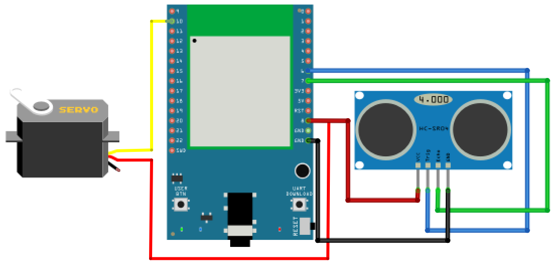
A typical servo has 3 wires, the red wire is for power, black or brown one should be connected to GND, and the other one is for signal data. We use PWM signal to control the rotation angle of the axis of the servo.
HC-SR04 is a module that uses ultrasound to measure the distance. The way it works is that first we “toggle high” the TRIG pin (that is to pull high then pull low). The HC-SR04 would send eight 40kHz sound wave signal and pull high the ECHO pin. When the sound wave returns back, it pull low the ECHO pin.
Follow the following connection diagram to setup the components.
-
2Code
#include <AmebaServo.h>

// create servo object to control a servo
// 4 servo objects can be created correspond to PWM pins
AmebaServo myservo;

const int servo_pin = 10;
const int trigger_pin = 6;
const int echo_pin = 7;

// variable to store the servo position
int pos = 0;

void setup() {
    Serial.begin(115200);
    pinMode(trigger_pin, OUTPUT);
    pinMode(echo_pin, INPUT);
    myservo.attach(servo_pin);
}

void loop() {
    float duration;
    int distance;

    // trigger a 10us HIGH pulse at trigger pin
    digitalWrite(trigger_pin, HIGH);
    delayMicroseconds(10);
    digitalWrite(trigger_pin, LOW);

    // measure time cost of pulse HIGH at echo pin
    duration = pulseIn (echo_pin, HIGH);

    // calculate the distance from duration
    distance = duration / 58;

    pos = map(distance, 2, 15, 15, 100);
    myservo.write(pos);

    Serial.print(distance);
    Serial.println(" cm");

    delay(100);
}
Code also avaliable on Github: https://github.com/HYuiii/Servo_Distance_Indicator
-
3Upload and Execution
Compile and upload to Ameba, then press the reset button. Open the Serial Monitor, the real-time calculated result is output to serial monitor and the servo module will also change its position according to the distance.
Servo Distance Indicator
Use the combination of servo module and ultrasonic sensor and our RTL8722DM_MINI board to measure the distance and to show on the scale.
 HYuiii
Discussions
Become a Hackaday.io Member
Create an account to leave a comment. Already have an account? Log In.