-
1Design Concept Process and Book Compartment Carve Out Step
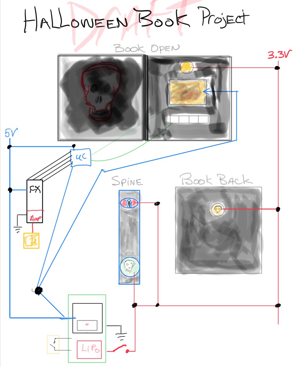
Below are some early design adaptations I made when thinking up ideas for the book. These were concepts I thought up, some of which were not used (see below). Some of the concepts were used while other concepts were thrown out. Again, this shows the concepts throughout my thought process. Some of the thrown-out concepts were due to book space limitations and time. As far as it relates to appearance, my goal is to not make the book too neat. I wanted to give an old decrypted look. So, the book outside and inside would not look totally intact. Because ideally, the Halloween book should look centuries old.
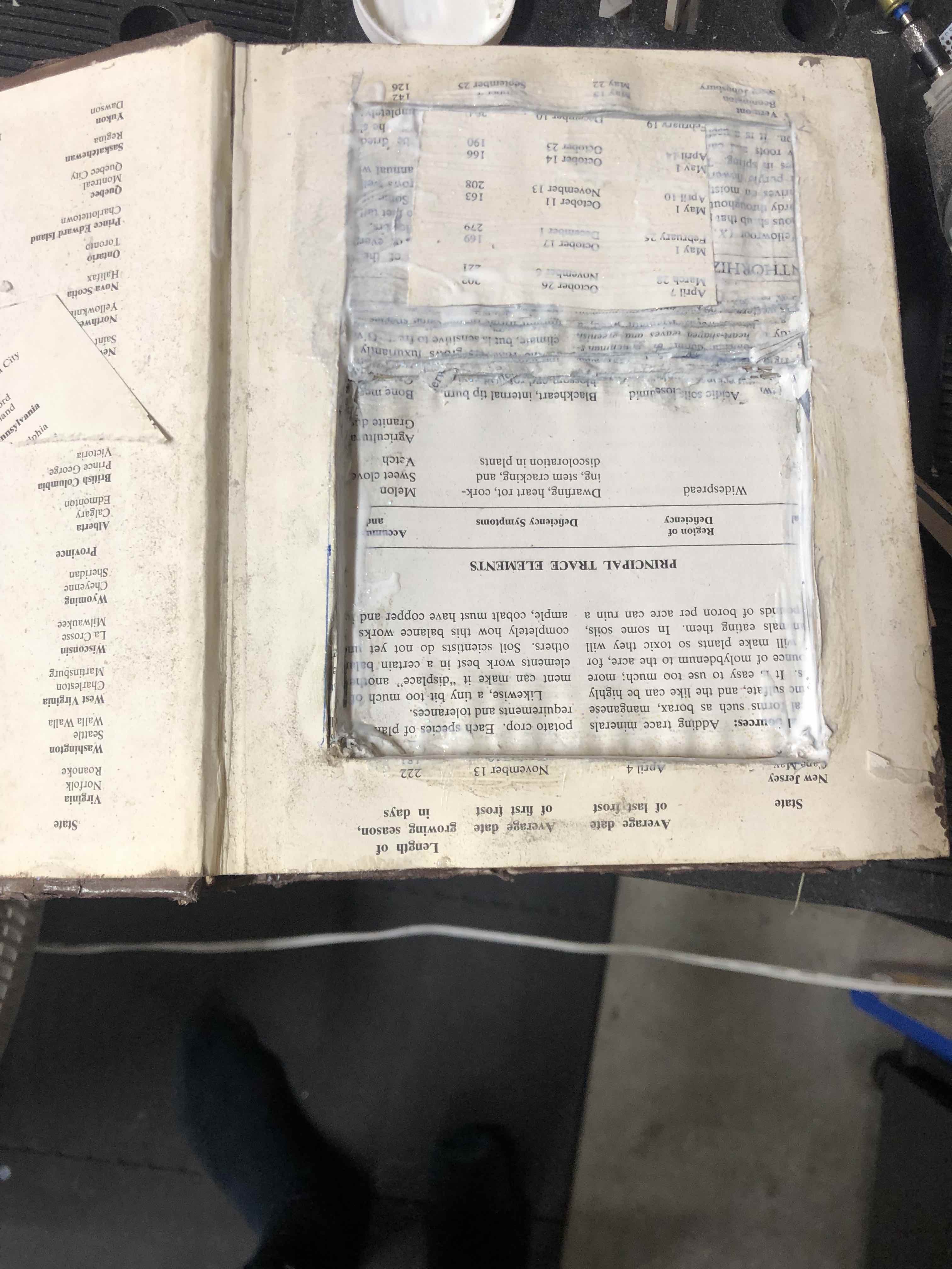
Depending on how the number of electronics you're going to embed into the Halloween book, you must choose a book that will have the space that you need. I chose a rather thick book that I purchased from a second-hand store. I need at least 4 compartments to house my electronics since I used over 7 different boards. Next, you have to carve out the needed compartments to house the electronics. I used a knife, I then used a Dremel with a circular cutting bit to speed and exact the space I needed.
![]()
![]()
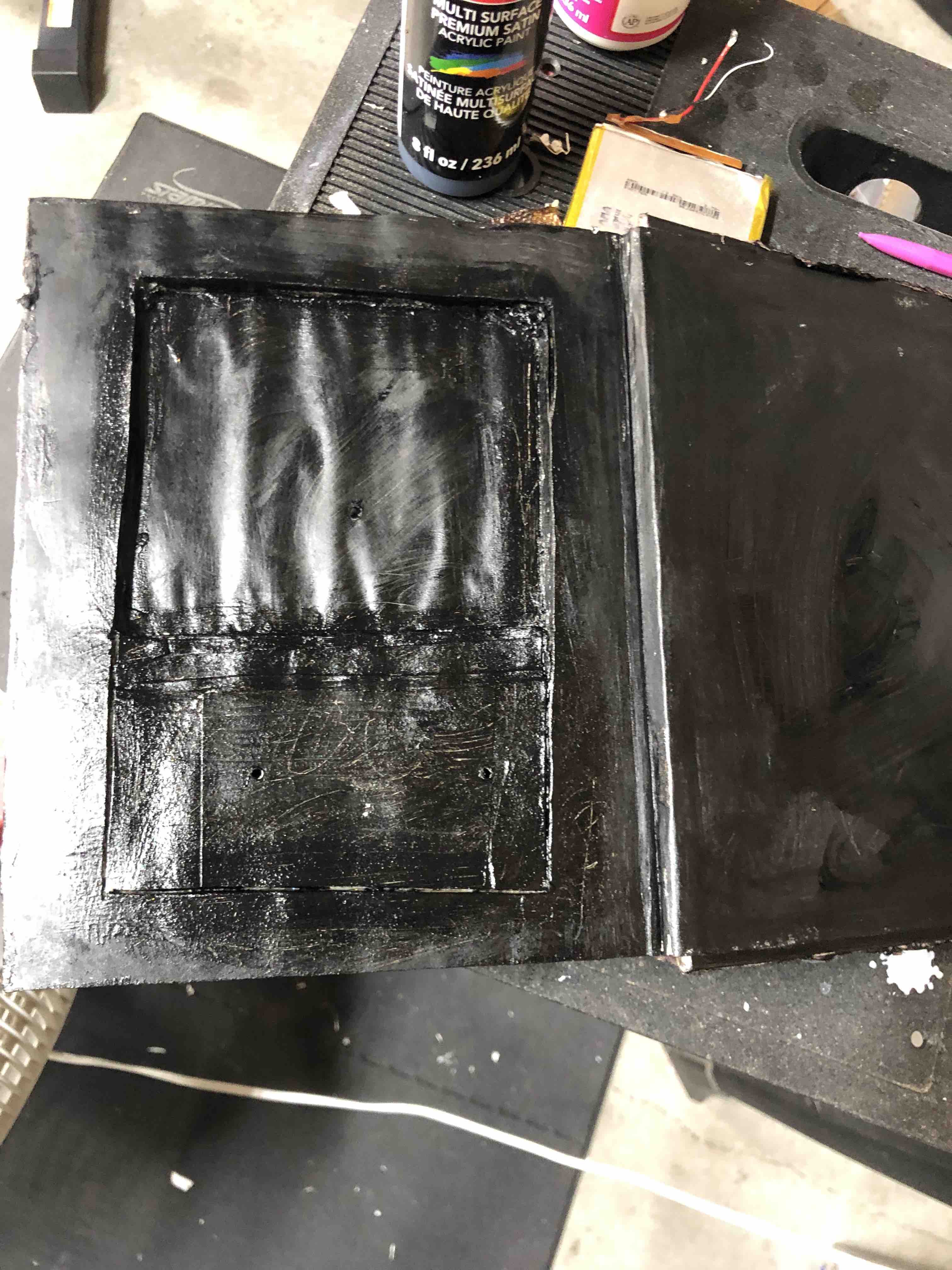
After carving out sections of the inside of the book, I applied mod podge to give a more firm and sturdy compartment.
![]()
After the mod podge dried I would then paint some of the inside sections with black acrylic paint.
![]()
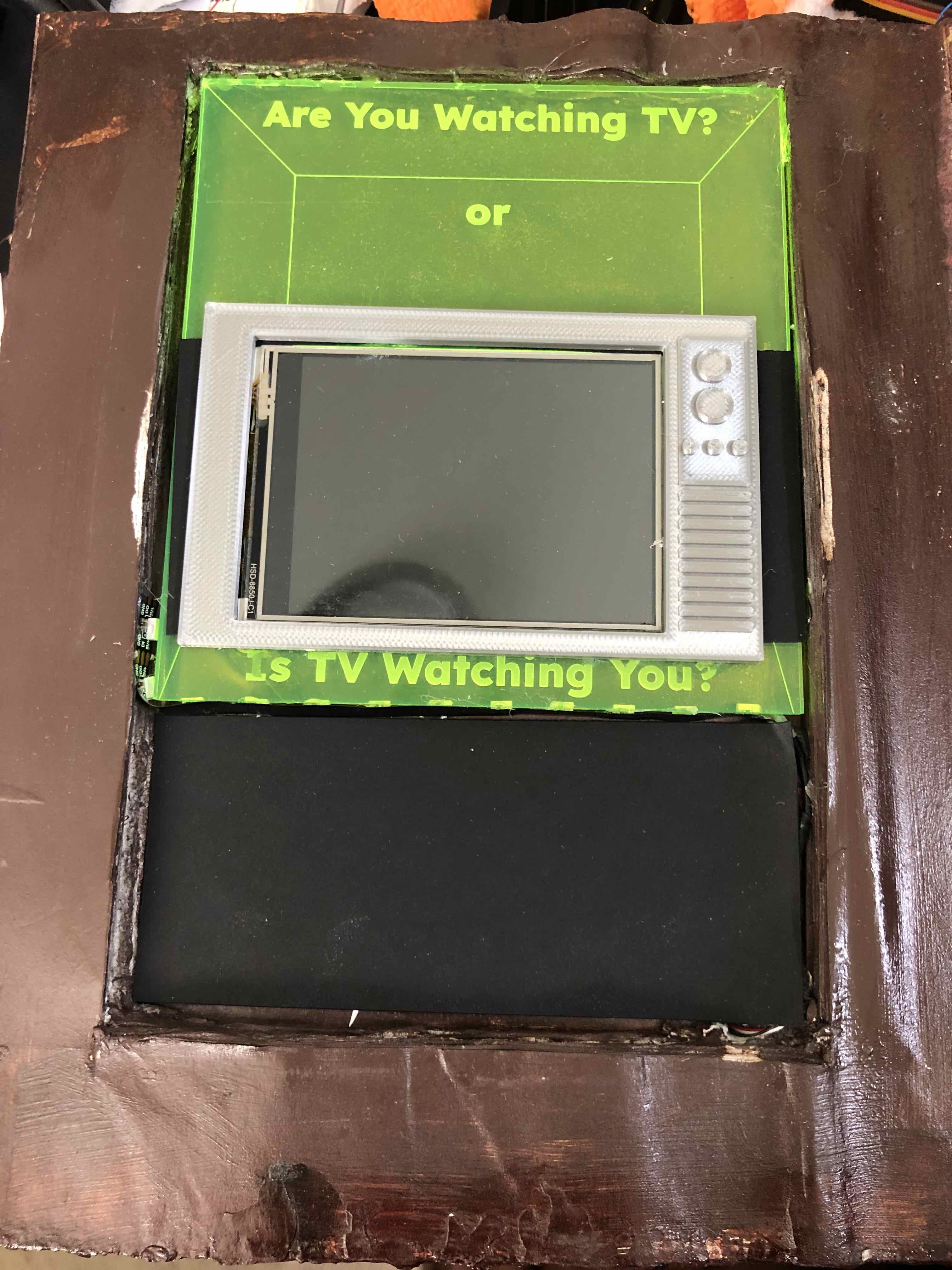
For the section where the displays were going to be housed, I painted them brown. Again, this is after the mod podge dried. I then painted that section brown. and stage the fitting of the inserts.
![]()
-
2Book Exterior Appearance Step
The third step is to start with the exterior of the book. I wanted to include some 3D printed Halloween effects such as a spider, skull, bone, etc.. So, I 3D printed those items. This is custom. You can add anything you want. Once printed, I glued them to the front of the book with hot glue. To create the spiderweb, I used hot glue. Once everything was glued in place I went to the next step.
The next step is to create a leathery, skin-type appearance. To do this, I used thin tissues and/or thin paper tiles. I damped the paper with water, laid it over the front first. Then I used a medium-sized artist brush and brushed on the mod podge glue. The wrinkles in the paper help with the effect. The more wrinkles the better it gives the old look (in my opinion)...see below. I let it dry and then moved to the back of the book and then the spine of the book. You can view a photo of the book before paint is applied, this photo is in the file section with the name 'BookBeforePaint.jpg'.
![]()
Once all was dry the next step was to apply the coloring. For this, I used a combination of colors/paint. I first used a wood stain (Red Oak) with a brownish color. I used about 3 coats, let it dry. I then accented it with some black, then gold paint to give the oldish antique look. Once completed and dried, I moved to the inside of the book. Once all is dry, the outcome should look similar to what's shown below.
![]()
-
3Internal Wiring Step
Since the compartments were completed already, I made holes for the wiring runs. I used the spine of the book to run the wire from front to middle to back and so forth. The book spine served as the wire conduit (see below). I used thin 30 gauge wire wrap. This wire is good since it could easily handle the voltage and current load.
![]()
-
4Additional Work Before Adding Electronics
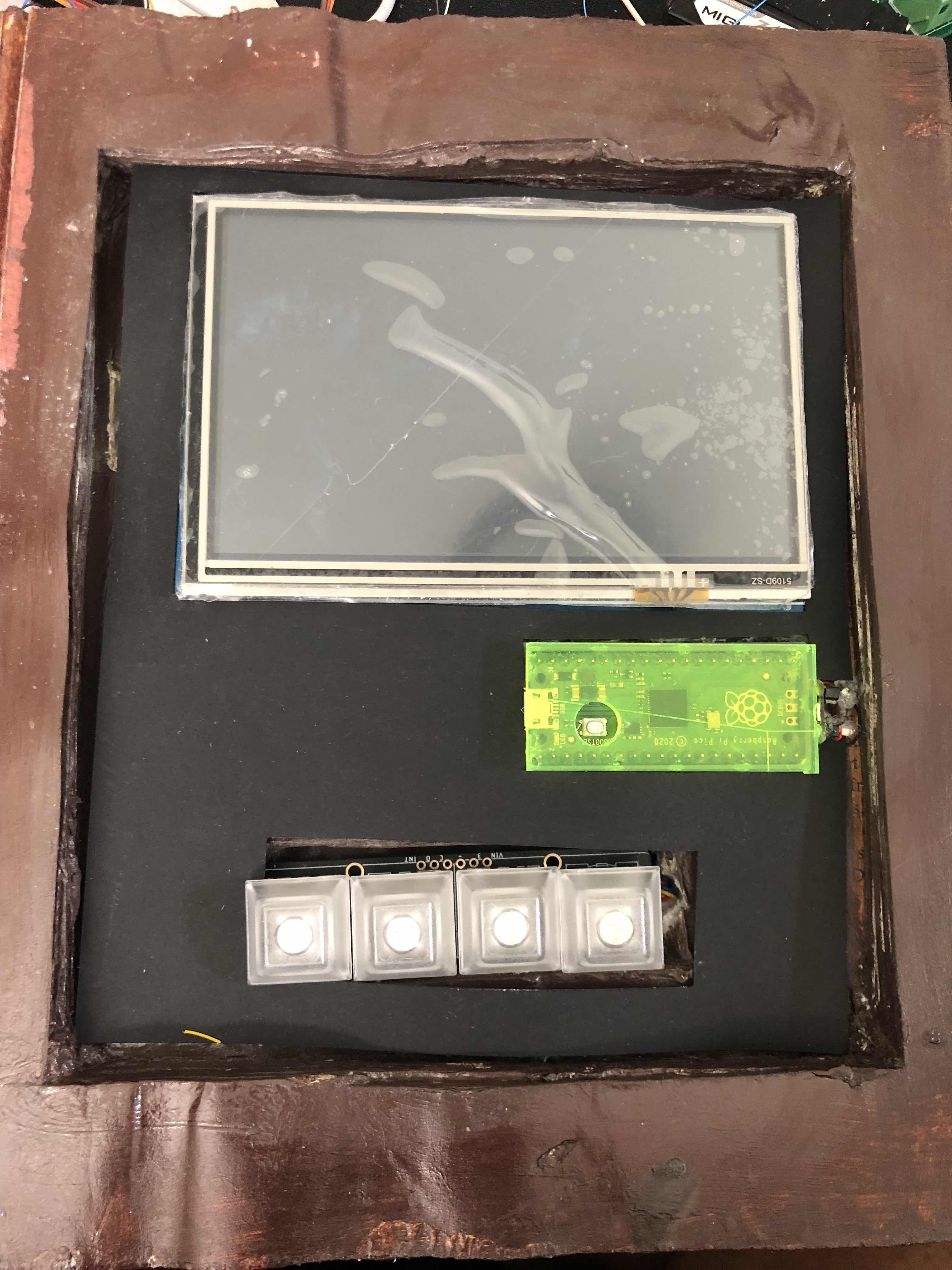
I used a laser cutter for the acrylic around the Adafruit py portal housing and Adafruit neopixels (.svg file is attached). I used the Cricut for the black paper for lining the Nextion display, PICO and Adafruit Neokey.
![]()
![]()
-
5Coding the electronics
CircuitPython version 6.3 is used on the PICO. (all files are attached).
The attached file 'code_FINAL.py' is the main file for the PICO. This file should be renamed 'code.py' and placed in the circuitpython drive.
The zipped file CRTPYTHON_LIBS_used.zip contains the libraries used and should be unzipped and placed in the lib folder on the PICO.
A third python file name 'srColors.py' is used for the neopixel colors. (do not rename this file) This should be placed in the PICO circuitpython drive root directory, not the lib directory
I used the Adafruit Clue and Adafruit Py portal to display gifs. For this, ciruitpython is used. (the files are attached). The Clue and pyportal are running stand-a-lone independent of the PICO.
For the Nextion display, it requires a setup in its GUI application to add photos (800x480) and text. In addition, since it will communicate over UART (RX/TX) to the PICO microcontroller, coding on the Nextion is done with the Nextion application is required for each page of photos that were added. I have the code included and can be viewed in the .HMI file. This complies all that data into a .HMI file (attached)
For the PICO, I used circuitpython (the file is attached). The code has description information. The PICO will control inputs from the 2 Neokeys. One neokey is used for 1 key press at a time (4 keys) and the second neokey is used for key combination presses(4 combinations).
The Adafruit FX board is configured with the sound files needed to activate with a neokey(s) is pressed. (the sound files are attached).
As a reminder, All coding files, sound and nextion files etc. are attached in the file section. You can view the attached files.
-
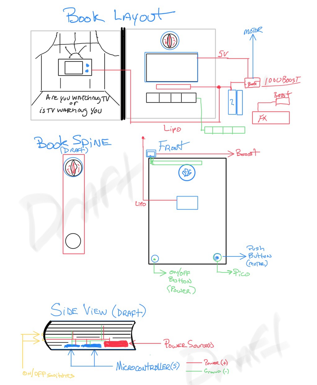
6Electronics Power Sources
I used 3 sources of power (shown below). And a 4th branched off of the PICO.
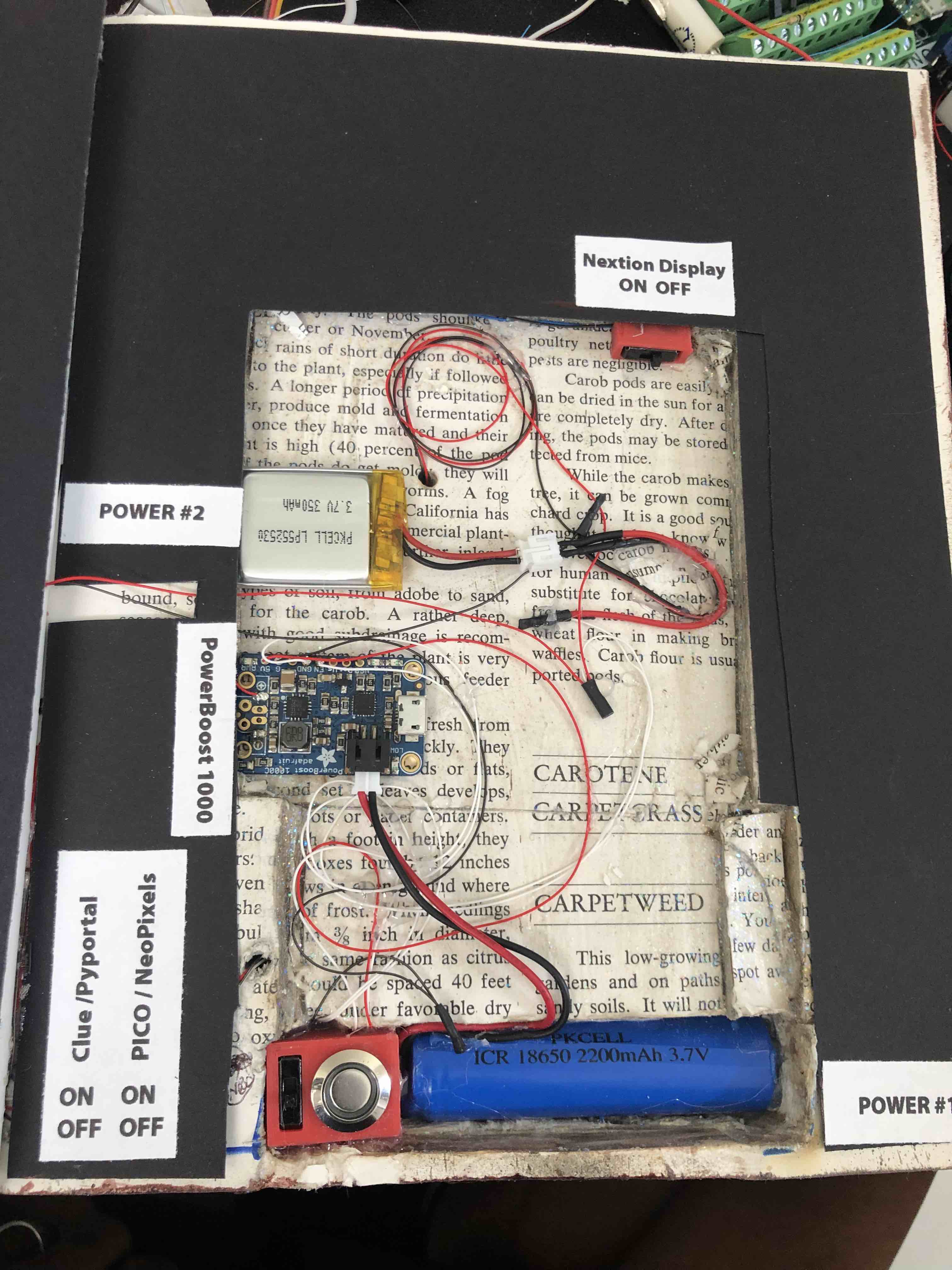
The first power source is using a 350mAh LiPo battery to power the Adafruit Clue and Adafruit PyPortal.
The second power source used is an Adafruit PowerBoost 1000 using a 2200mAh LiPo to power the PICO
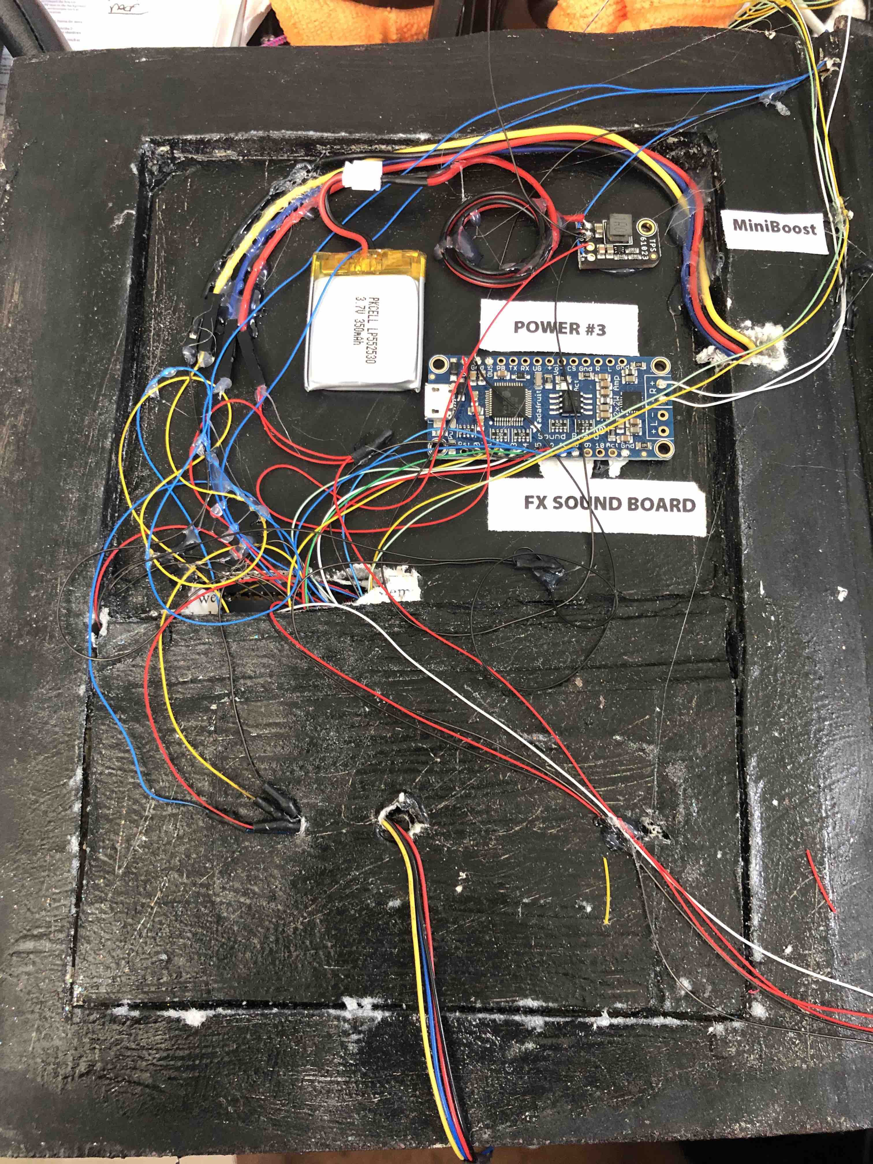
The third power source used is an Adafruit MiniBoost using a 350mAh LiPo to power the Nextion display
The fourth power source used is branched off the PICO 3V3 pin to power the neopixel strip
Located in the front of the book:
![]()
Located in the back of the book:
![]()
-
7Electronics Connectivity
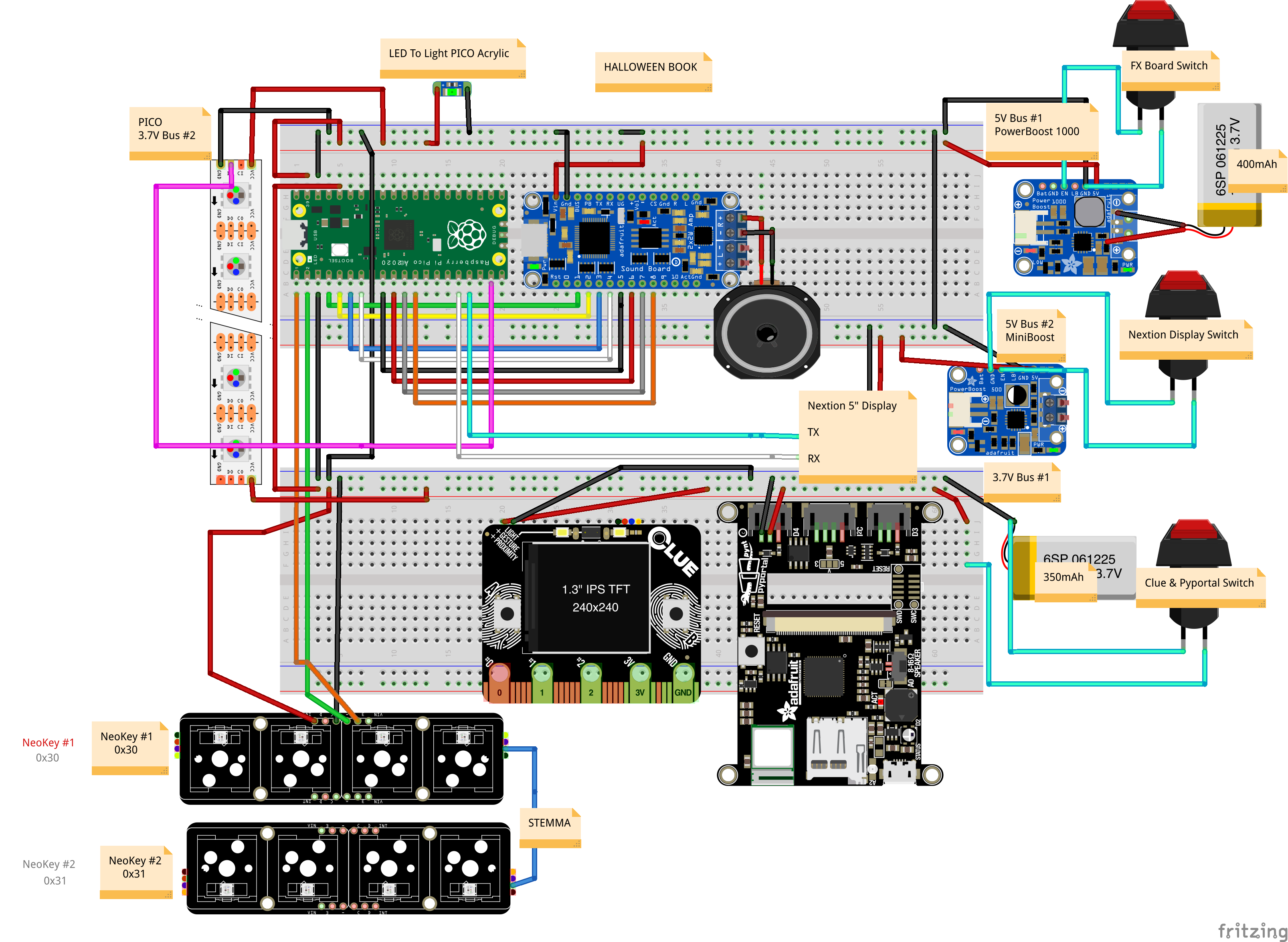
You can view the Fritzing diagram for the connectivity. But the physical connectivity consisted of wire-wrap, soldering, hot glue.
![]()
-
8Additional Notes
Adafruit LED sequin glued to end PICO acrylic to give a glow. this LED is connected to PICO 3V3 pin
2nd Adafruit Neokey added by stemma connector
edThe book is made to not look too neat, to give the aged and decrepit look.
I also included the Adafruit FX board triggering sounds by the Pico GPIO mapping from input from NeoKey#1 and Neokey#2 and images displayed on the Nextion display
-
9Raspberry Pi PICO GPIO to Adafruit FX Soundboard
I included a fritzing diagram 'HalloweenBookFX_Sound.fzz' to show the GPIO mapping amoung the PICO, Neokeys#1 / #2, FX soundboard and image displayed on the Nextion display.
-
10Equipment/Tools Used
Prusa i3 MK2
PLA 1.75 Filament
Glowforge Laser
1/8" Transparent Green Acrylic
Cricut Maker
Dremel
Black Project Paper
Soldering Iron (TS100)
Digital Caliper
Wire Wrap Tool
Diag Cutters / Needlenose Pliers
Wire Ware Wire (30 gauge)
Tissue/Thin Paper Towel
Mod Podge
Gold Acrylic Paint / Black Acrylic Paint
Wood Stain (Red Oak)
Breadboard(s) for testing
Interactive Halloween Book
A Halloween book that is interactive with video, gifs, sounds, and keycaps.
Discussions
Become a Hackaday.io Member
Create an account to leave a comment. Already have an account? Log In.