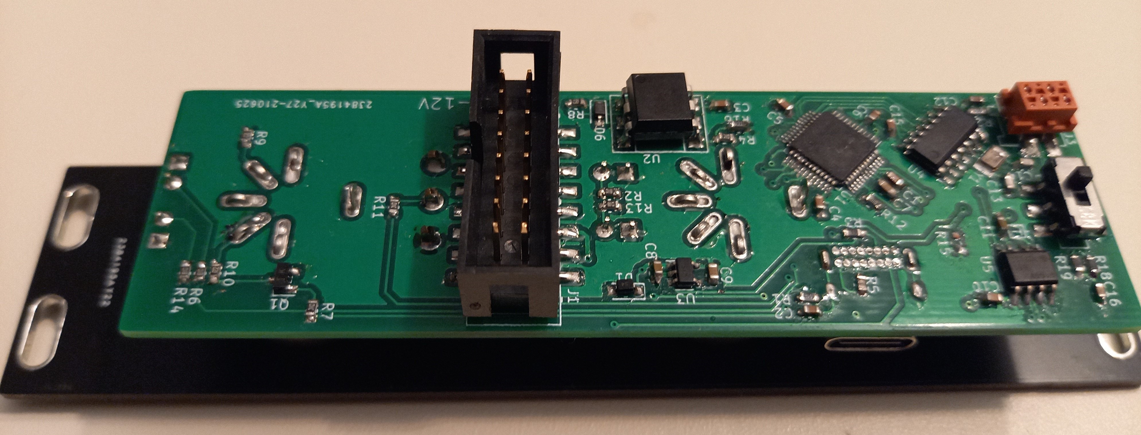
The DIN-5 module was the most straight forward. Most of this circuit is retained from the previous I2C version. Its purpose is to act as a gateway between the classical DIN-5 MIDI transport, and the CAN bus. The schematics and PCBs can be viewed on CADLab.
This module has one DIN input, and one DIN output. There is a switch to decide if messages from the input should be merged with the output (Thru + Out). It also has a USB-C connector to program it via a bootloader.

The assembled module looks like this.

The front-plate is held in place by the DIN connectors and can't be removed after it has been assembled. This made reaching the programming header a challenge.
The LEDs shine through the PCB. The Solder mask and copper has been removed from both sides in that area, and the FR-4 acts as a diffuser.
 David
David
Discussions
Become a Hackaday.io Member
Create an account to leave a comment. Already have an account? Log In.