This module is a general control voltage module. It can generate DC voltages, low frequency signals and envelopes. It is intended to be configurable so it can be used in many different setups. It should also be possible to save configurations to EEPROM to recall them later, and quickly change between them. The schematics and PCBs can be viewed on CADLab.
The analog voltages are generated by filtering PWM. This leads to a trade-off between speed, ripple, and resolution. The speed of the outputs doesn't need to be higher than 20Hz. A resolution around 16-bits should be plenty for a prototype. And the ripple should be very low, we don't want it to sound shaky. This design is using four PWM outputs which are multiplexed, using a sample-and-hold method. The capacitors used in the sampling are also part of the low-pass filters, to reduce the part count. The voltage is then scaled, offset, and buffered by an opamp. Bi-color LEDs are connected to these outputs to indicate their current voltage.
A general module like this will need a good user interface so it isn't frustrating to configure. A display module would be very versatile, but I've had some bad experience with them. So I decided to use an 8x5 LED-matrix instead. This means the info will be a bit cryptic, but it is easy to read, and a stylized look like this can be cool. This module is meant to be "set and forget" so it doesn't need immediate access to all parameters. So it has three buttons to navigate menus. It should be good enough for a prototype anyway.
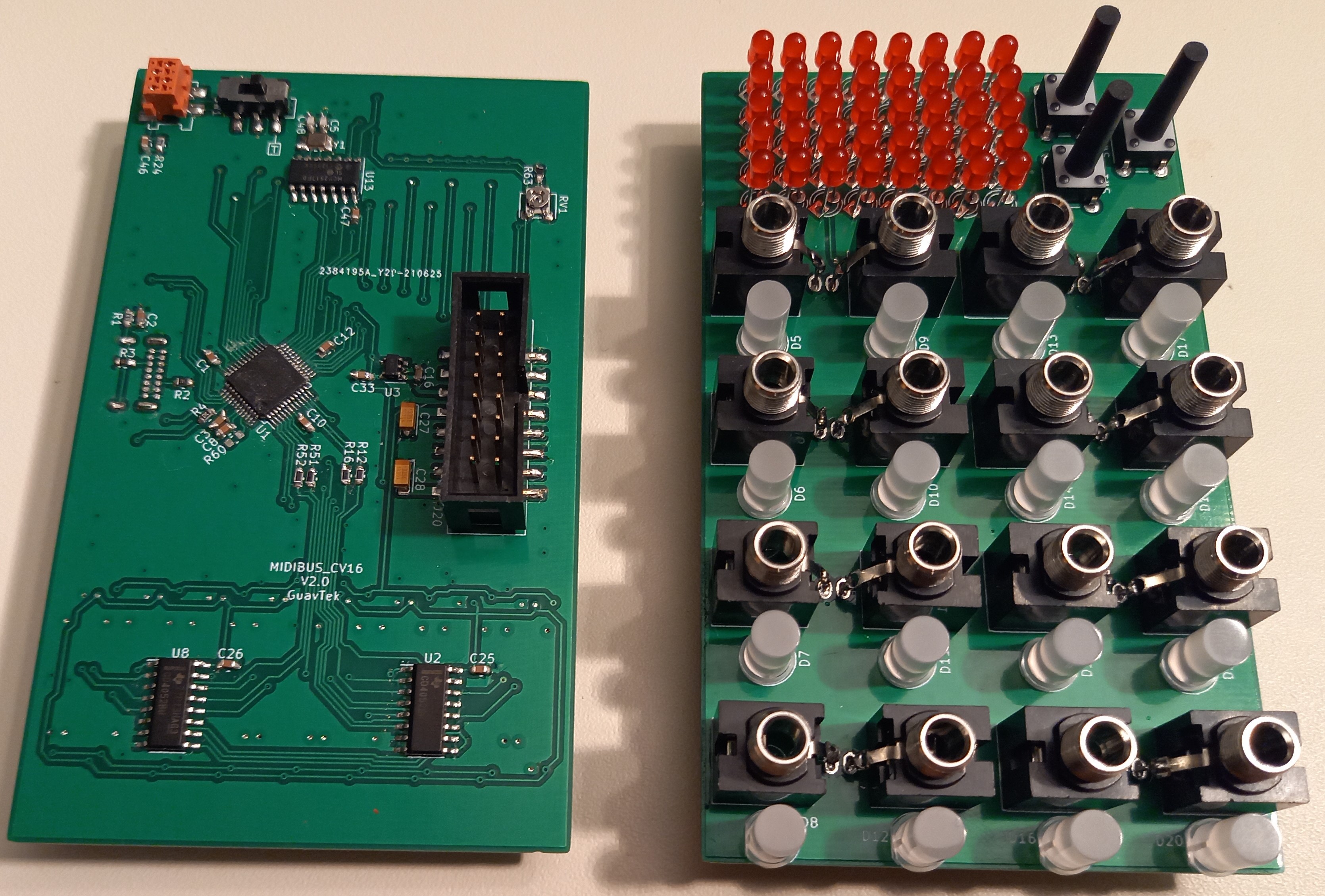
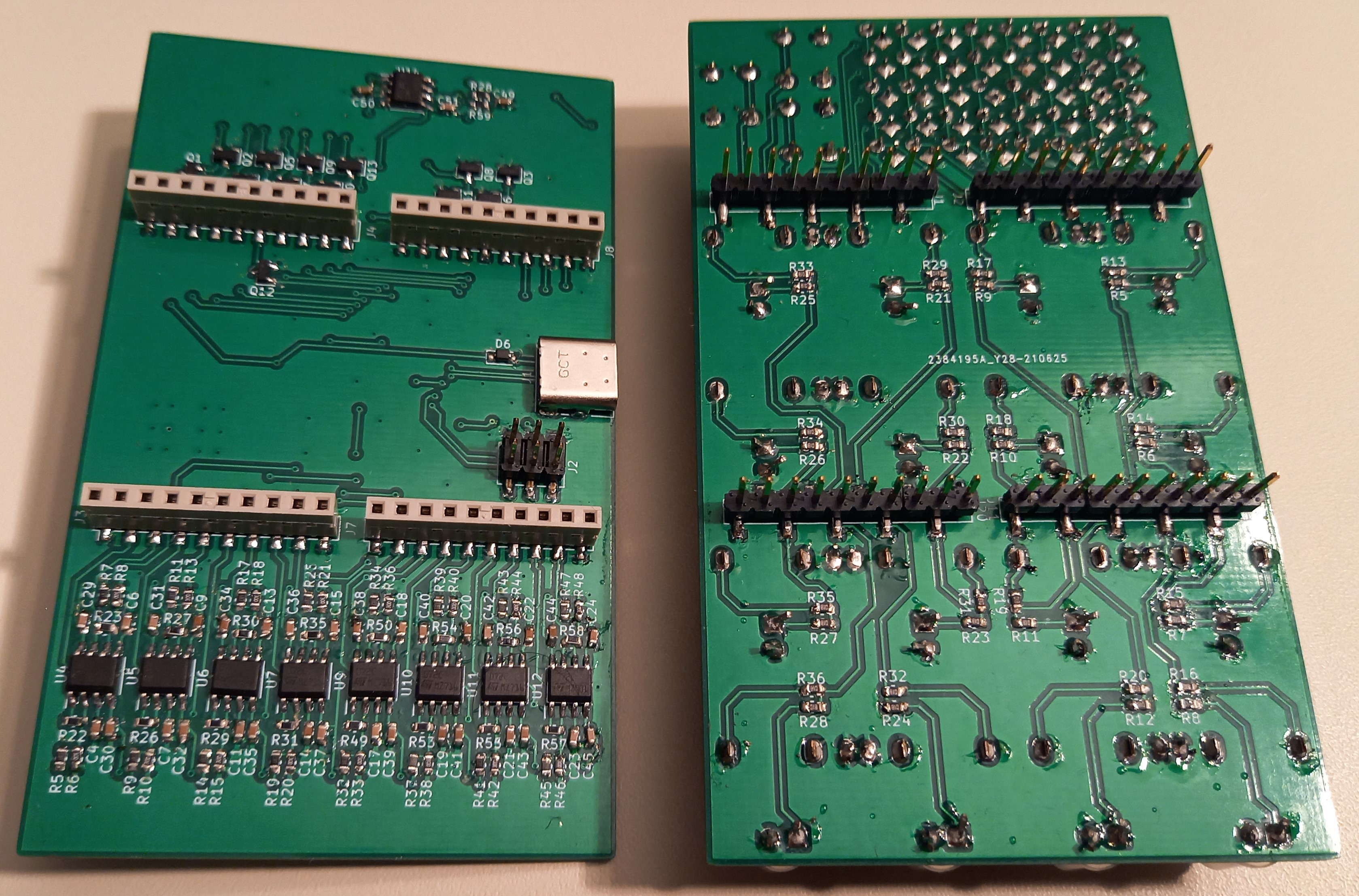
The module is a sandwich of two PCBs.
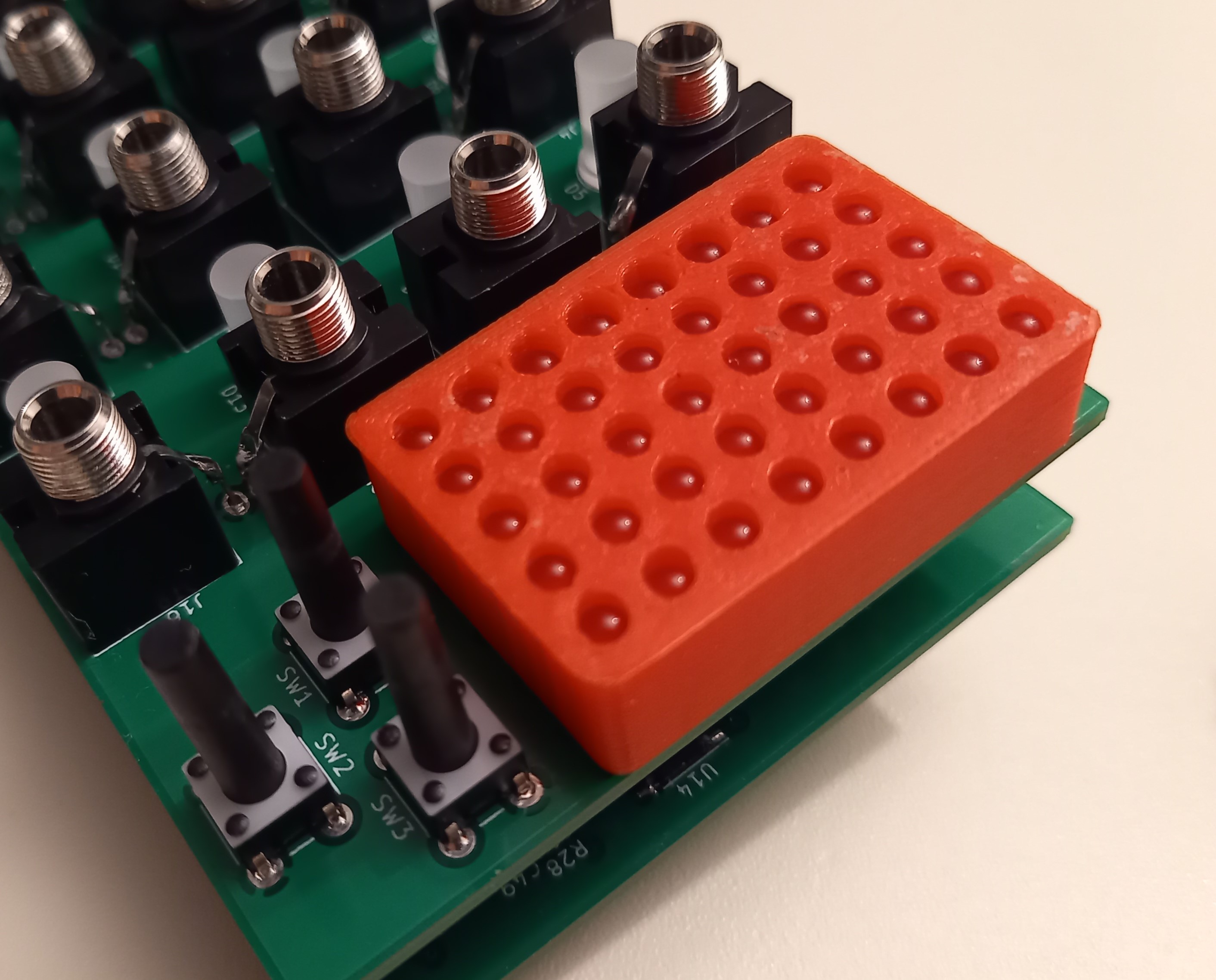
After some testing I discovered that the LED-matrix was a bit dim, but there was still a lot of bleed between the pixels. I did expect it to bleed, but I was somehow surprised by the amount. To fix the bleeding I 3D-printed a separator. As for them being dim: I should get some brighter LEDs, 50mcd was not enough.
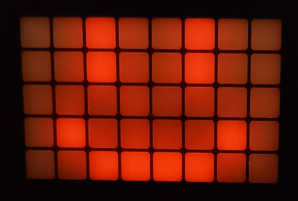
Without the separator
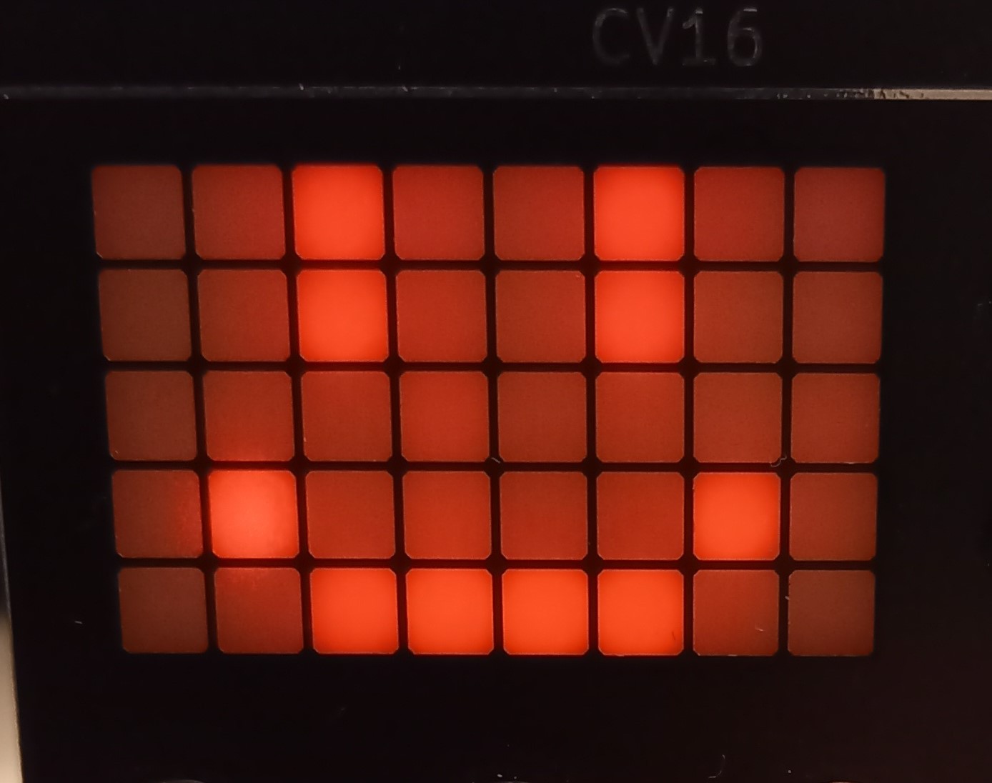
With the separator
 David
David
Discussions
Become a Hackaday.io Member
Create an account to leave a comment. Already have an account? Log In.