Porting MicroPython to the FT10 Smart Watch
To make the experience fit your profile, pick a username and tell us what interests you.
We found and based on your interests.
STK8321.pdfAdobe Portable Document Format - 1.67 MB - 10/16/2021 at 00:52 |
|
|
In the last project log I explained that one problem is that not all patch functions that zephyr requires are exported in the RTL8762C SDK. But some are.
patch_osif_os_sys_time_get = 0x0020110c ; patch_osif_os_task_signal_send = 0x00201144 ; patch_osif_os_msg_send_intern = 0x00201184 ; patch_osif_os_timer_create = 0x002011d4 ;
We also know the addresses of the functions that are being patched.
os_sys_time_get = 0x0002678f ; os_task_signal_send = 0x00026b07 ; os_msg_send_intern = 0x00025fe5 ; os_timer_create = 0x00026bd7 ;
It's important to node that the function addresses are odd, since they are ARM thumb code. The real address of the code is the function address -1.
I tried to read from these addresses using rtltool, but apparently only got garbage, no real arm thumb code. Instead I could leverage my existing MicroPython port, since it implements memory access.
>>> from machine import mem8, mem32
>>> os_sys_time_get_start = 0x0002678f-1
>>> os_sys_time_get_end = 0x000267a9-1 # address of next function
>>> os_sys_time_get_bytes = bytearray([mem8[addr] for addr in range(os_sys_time_get_start, os_sys_time_get_end)])
>>> print(os_sys_time_get_bytes)
bytearray(b'*H\x08\xb5\x01h!\xb1hF\x88G\x08\xb1\x00\x98\x08\xbd\xbd\xe8\x08@\x00\xf0\xc0\xba$')
This byte code we then diassemble. I'm using pwntools pwnlib for this.
In [1]: from pwnlib.asm import disasm
In [2]: os_sys_time_get_bytes = bytearray(b'*H\x08\xb5\x01h!\xb1hF\x88G\x08\xb1\x00\x98\x08\xbd\xbd\xe8\x08@\x
⋮ 00\xf0\xc0\xba$')
In [3]: os_sys_time_get_assembly = disasm(os_sys_time_get_bytes, vma=0x00026b07-1, arch='thumb')
In [4]: print(os_sys_time_get_assembly)
The result is the following assembly.
2678e: 482a ldr r0, [pc, #168] @ (26838 <.text+0xaa>)
26790: b508 push {r3, lr}
26792: 6801 ldr r1, [r0, #0]
26794: b121 cbz r1, 267a0 <.text+0x12>
26796: 4668 mov r0, sp
26798: 4788 blx r1
2679a: b108 cbz r0, 267a0 <.text+0x12>
2679c: 9800 ldr r0, [sp, #0]
2679e: bd08 pop {r3, pc}
267a0: e8bd 4008 ldmia.w sp!, {r3, lr}
267a4: f000 bac0 b.w 26d28 <.text+0x59a>
267a8: Address 0x267a8 is out of bounds.
The code loads a value from 0x26838 into r1, and if the value is not 0 (cbz), the value in r1 is interpreted as a function pointer and branched to (blx).
>>> hex(mem32[0x26838])
'0x20110c'
Reading from 0x26838 we can see that the value is indeed the same as the function pointer patch_osif_os_sys_time_get.
Using this approach we can recover the patch functions pointers that are not yet exported in the SDK.
We can take advantage of the fact that the check the patch function check and call is the first thing that happens in each os function, so we only need to read the first couple of bytes.
The exact amount depends on the number of parameters of the function, which might cause some registers to be pushed to stack before the address of the pointer is loaded.
I shelved this project for a while, but my interested rose again after I started working with zephyr professionally.
Realtek SoCs also were introduced in the Zephyr 4.4 release. This includes the RTL8752H, a sibling of the RTL8762C, which looks very similar. In fact, most of the source files in the Realtek HAL are named rtl876x.
Additionally, there is a new UART programming tool, apparently written by the same team. This essentially supersedes my own implementation.
Seeing this, I was hopeful that running Zephyr on the RTL8762C was going to be easy. While most porting effort were quite straight forward - copying the RTL8752H, modifying some magic number and addresses - but I quickly hit a brick wall.
Zephyr relies on certain patch address in RAM to be exported. The problem is, that the RTL8762C SDK doesn't exports all the functions that the RTL8752H SDK does.
Searching for more resources on this MCU platform, I discovered that the vendor put a playlist on YouTube where an engineer goes over every aspect of the hardware and SDK.
Based on the reverse engineering efforts outlines in the last logs, I developed a python utility similar to esptool - which I hence named rtltool.
The functionality is very rudimentary. It provides commands for reading, erasing, writing and verifying contents of the micro controllers flash via UART.
To obtain a complete flash dump of the FT10 smart watch, run
./rtltool.py read_flash 0x00800000 0x00800000 ft10-flash_dump.bin
This can then be verified with
./rtltool.py verify_flash 0x00800000 ft10-flash_dump.bin
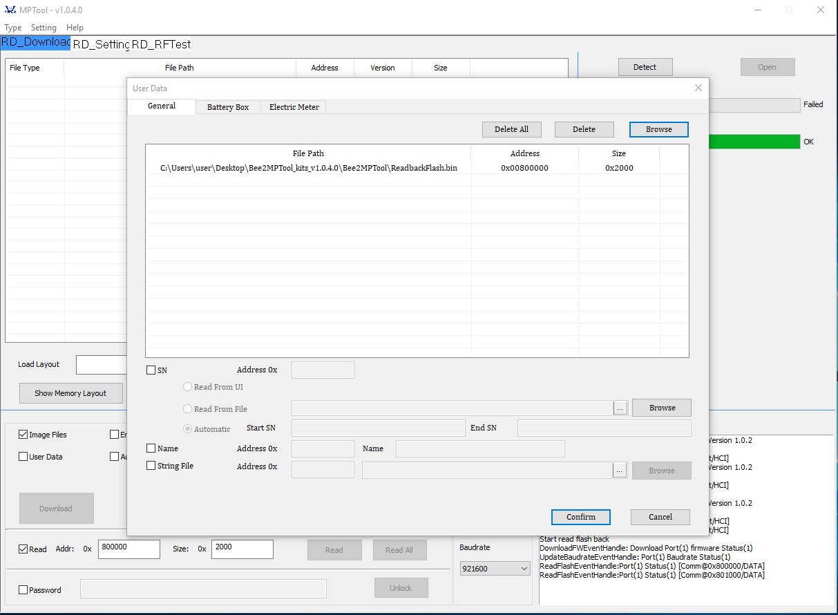
After using the flashing tool to create a flash dump for backup reasons, I read a 8kiB (0x2000) section of the start of flash and then wrote it back using the User Data feature of the tool.
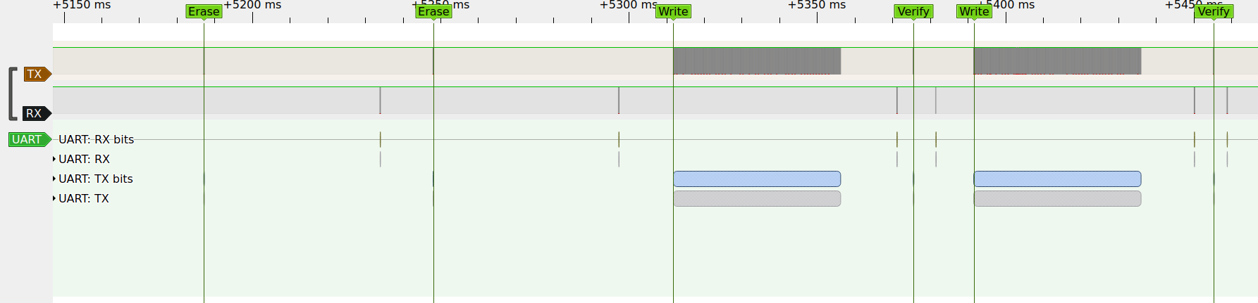
The MessageBox logs two EraseFlash and then two consecutive WriteFlash and VerifyFlash events.
This is also visible in the captured signals. I also tested the Chip Erase function of the tool and captured its operation and response code. By checking the numbers of bytes transmitted, recording more examples and using reveng I found more uses of the CRC.
| Protocol Phase | Op/RespCode | Parameters: length |
| TX: erase sector | b"\x87\x30\x10" | - address: 4B - length b"\x00\x10\x00\x00": 4B- CRC-16/ARC: 2B |
| RX: acknowledge erase sector | b"\x87\x30\x10" | - stuffing (b"\x00"): 5B- CRC-16/ARC: 2B |
| TX: erase 16 sectors | b"\x87\x35\x10" | - address: 4B
- length b"\x00\x00\x01\x00": 4B- CRC-16/ARC: 2B |
| RX: acknowledge erase 16 sectors | b"\x87\x35\x10" | - stuffing (b"\x00"): 5B- CRC-16/ARC: 2B |
| TX: erase all | b"\x87\x31\x10" | - CRC-16/ARC: 2B |
| RX: acknowledge erase all | b"\x87\x31\x10" | - stuffing (b"\x00"): 5B- CRC-16/ARC: 2B |
| TX: write | b"\x87\x32\x10" | - address: 4B - length: 4B - payload: nB - CRC-16/ARC: 2B |
| RX: acknowledge write | b"\x87\x32\x10" | - stuffing (b"\x00"): 5B- CRC-16/ARC: 2B |
| TX: verify | b"\x87\x50\x10" | - address: 4B - length: 4B - CRC-16/ARC of flash content: 2B - CRC-16/ARC: 2B |
| RX: acknowledge verify | b"\x87\x50\x10" | - stuffing (b"\x00"): 5B- CRC-16/ARC: 2B |
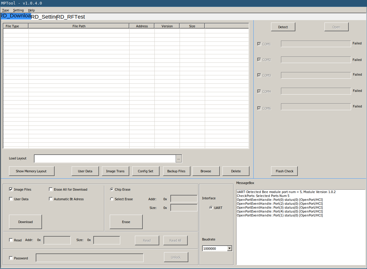
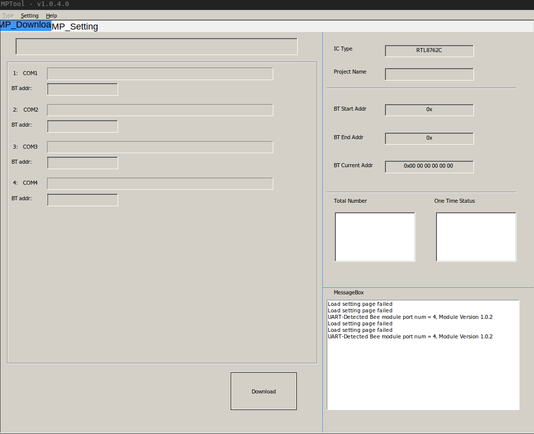
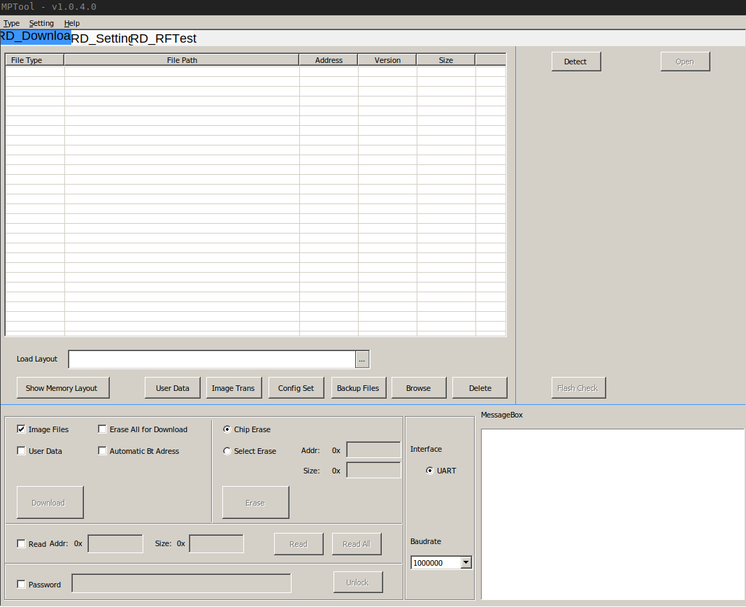
After finding a repository with software utilities for this chip, I tried to use the MPTool, which after first inspections seems to provide flash read, erase and write functionalities. When clicking the Detect button it lists all available COM ports and enables the Open button. When clicking this, all ports returned fail.
On the smart watch I found five labeled test points - GND, RX, TX, RST and LOG. To make everything more accessible I opened and unfolded the smart watch into a perf board. The PCB is held in place by tiny screws through it's original mounting holes, which land in holes of the perf board. The test points are connected with small solid core wires to the header on the top left.
I removed the sticker antenna from the watch housing and used a short length of wire to solder it to a test point that is opposite to the spring that normally makes contact with the antenna. I also used more solid core wires to give easy access to the LCD signals for probing at the bottom pin header.
The image shows an FT232 also used as logic analyzer. Due to bad performance and sample rate discrepancies I later switch to a Saleae Logic clone
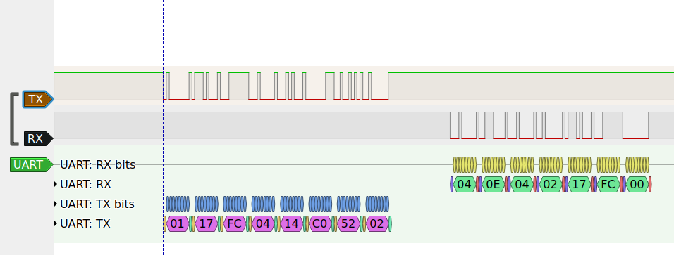
After some testing around, I found out that the LOG signal acts like as a strapping pin, similar to GPIO0 of the ESP32. If it is pulled to GND during hardware reset, one of the the COM ports report OK when clicking the Open button. This is caused by a handshake, which consist of a magic byte string that is answered by the MCU with another magic byte string.
| Protocol Phase | OpCode | Parameters |
| TX: handshake request | b"\x01\x17\xFC\x04\x14\xC0\x52\x02" | None |
| RX: acknowledge handshake | b"\x04\x0E\x04\x02\x17\xFC\x00" | None |
Sadly apart from the handshake, nothing else seemed to work under wine. Trying to read flash content caused the application to freeze after transferring a bunch data, as indicated by the LEDs od the USB UART adapter. Therefore I was forced to use with a Windows VM instead of wine.
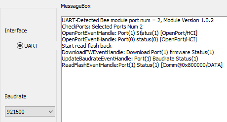
According to the Memory User Guide the flash starts at address 0x00800000. Reading the first 1kiB (0x400) the tool prints the following logs in the message box.
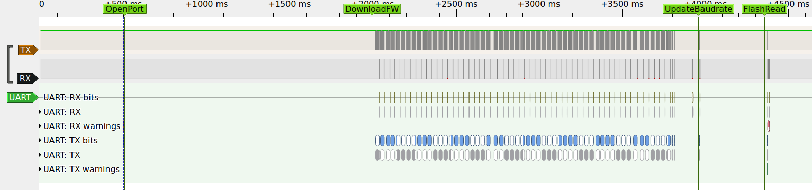
It logs four events called OpenPort, DownloadFW, UpdateBaudrate and ReadFlash. These events are clearly visible when looking at the signal
Looking through the files next to the flasher tool I found one called firware0.bin. Comparing its content with the recording, I found the section where it's transmitted. This is reminiscent of the flasher stub of esptool.
$ xxd -g 1 Bee2MPTool_kits_v1.0.4.0/Bee2MPTool/Image/firmware0.bin | head -n 2
00000000: 05 00 03 01 92 27 00 00 00 01 00 00 6d 67 de f1 .....'......mg..
00000010: 3e 33 e8 11 b1 02 4d 2d f4 0c de 01 f0 38 20 00 >3....M-.....8 .
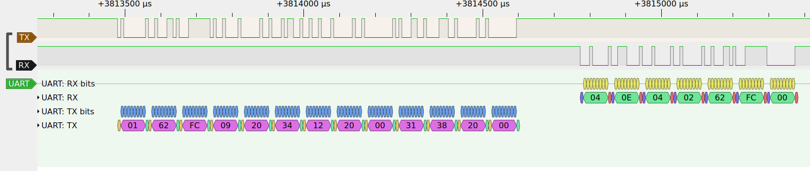
All frames but the last was are preambled with 0120FC, followed by one bytes containing the length of the rest of the frame, then one byte with the frame number, followed by up to 252 bytes of data. Every frame is acknowledged by the MCU with 040E0502FC00 followed by one byte with the frame number.
After the last frame is finished, a magic sequence is transmitted, that presumably causes the stub to run, which is acknowledged with 040E040262FC00. After ~100ms delay the MCU sends another 70 bytes, presumably containing some information about it, like version number and address ranges.
| Protocol Phase | Op/RespCode | Parameters: length |
| TX: load flasher stub frame n | b"\x01\x20\xFC" | - frame length: 1B - frame number: 1B - payload: 1..252B |
| RX: acknowledge flasher stub page n | b"\x04\x0E\x05\x02\xFC\x00" | - frame number: 1B |
| TX: magic | b"\x01\x62\xFC\x09\x20\x34\x12\x20\x00\x31\x38\x20\x00" | None |
| RX: acknowledge magic | b"\x04\x0E\x04\x02\x62\xFC\x00" | None |
| RX: system info? | b"\x87\x00\x10" | - b"\x00\x3C\x00\x00\x00\x00\x00\x20\x00\x00\x00\x01\x00\x00\x00\x80\x00\x00\x00\x80\x00\x00\x00\x00\x00\x00\x00\x00\x00\x17\x40\x0B\x00\x58\x54\x32\x35\x46\x36\x34\x42\x00\x00\x00\x00\x00\x00\x00\x00\x5C\xC2\x14\x84\x44\x9C\x81\x8C\x86\x29\x88\x5A\x3B\x02\x48\xB0"... |
A quick search for RTL8762CK on the usermanualwiki yields some results, such as the SDK User Guide outlining general firmware development steps as well as showcasing some programming software, the Memory User Guide showing the memory map, OTA User Manual describing an update mechanism over BLE, as well as the Flash User Guide and Peripheral Manual documenting some hardware function interfaces of the SDK.
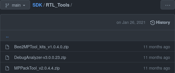
Looking for the IC marking RTL8762 on GitHub one finds a repository containing an RTL_Tools directory with zip files.
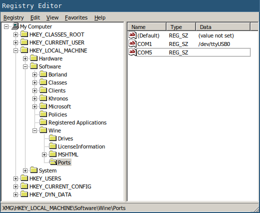
Following the wine wiki I redirected /dev/ttyUSB0 to COM0 with wine regedit.
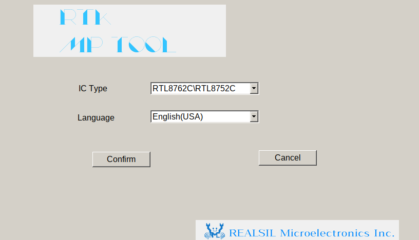
Running wine Bee2MPTool_kits_v1.0.4.0/Bee2MPTool/MPTool.exe for the first time crates a Log directory and MPToolSetting.ini file. The title screen let's one choose between IC types and languages
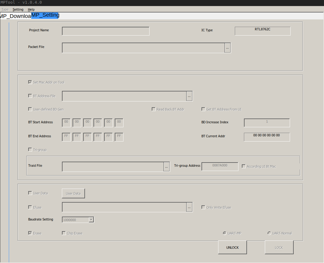
After that one isn't greeted with many options. Clicking the unlock button let's one set a password which later can be used to unlock again, and is stored as plaintext in the ini file.
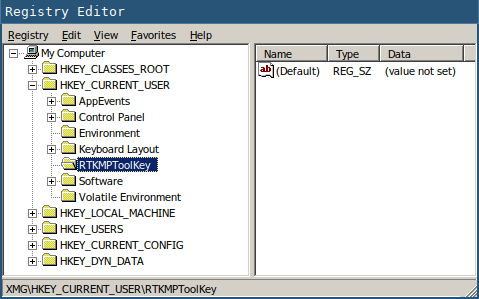
It's only after running wine Bee2MPTool_kits_v1.0.4.0/Registry\ Set/RegistrySet.exe That the Type menu of the window becomes available. The RegistrySet.exe simply adds the key RTKMPToolKey to the HKEY_CURRENT_USER in the registry.
Switching from Type>MP to Type>Debug switches the window content to an interface the appears to be used for reading and writing sections of the flash.
The MCU on the watch is marked RTL8762CK.
One seller listed the "G-sensor" as STK8321, which is a "Digital Output 3-axis MEMS Accelerometer" featuring I²C and some interrupt pins.
I also suspect the heart rate sensor and touch screen to be I²C devices.
The LCD is marked, but a search on the internet doesn't yield anything of relevance. The watch is advertised to have an 1.3 inch240x240 IPS LCD. It's connected via 18 Pins and a quick analysis with the scope showed bursts of 5MHz square waves packages on one signal, indicating either SPI or parallel bus. Maybe it's a ST7789 controller.
Create an account to leave a comment. Already have an account? Log In.
Become a member to follow this project and never miss any updates
mitxela
Stephen Holdaway
Hugo Melder
jaromir.sukuba