 scubabear
-
1Making the Central Display
Hire Jeremy to do the artwork for you. Then set up the illustrations in Illustrator for printing & routing.
Print the graphics in reverse using a Mimaki onto 1/8" clear polycarbonate:
After printing the transparent colors, print a white backer. This will make the colors pop and add some diffusion for the LEDs.
-
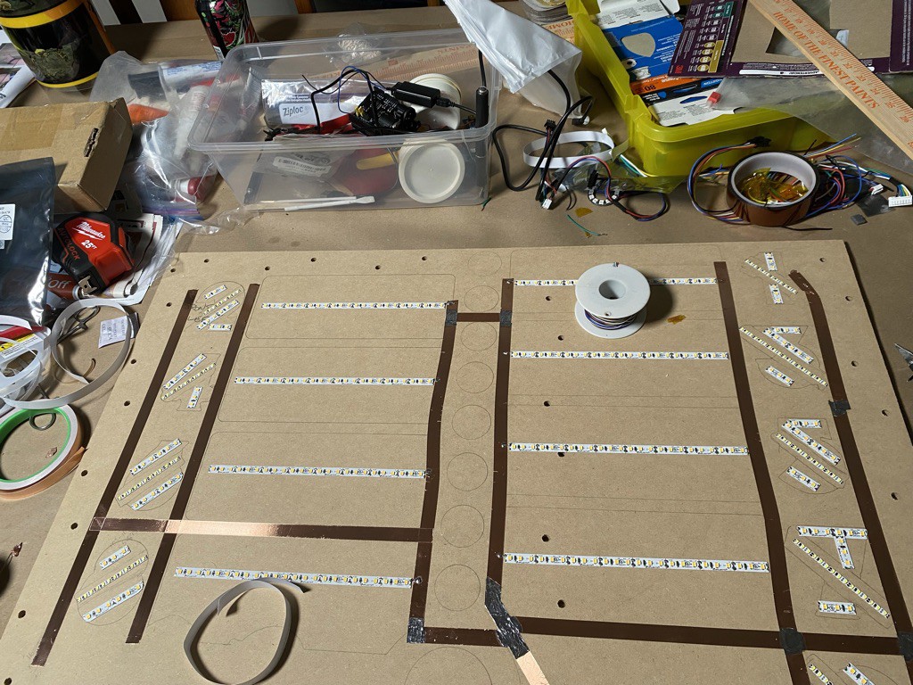
2Make the Backers to direct & confine the LED Backlights
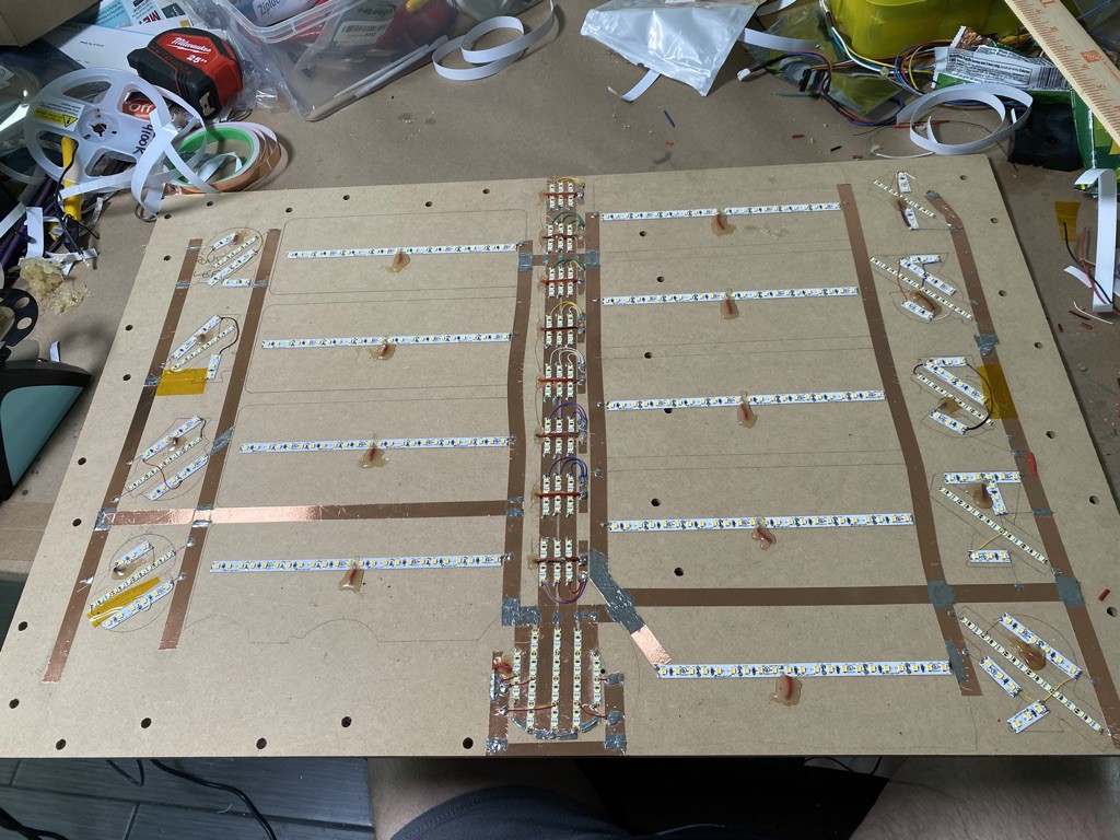
Stick LED tape down onto 3/8" MDF to create the light source/backer. Use foil tape to make buses; you won't want to use actual wire because that thickness could cause light leak problems later on.
![]()
Use 30ga wrap wire to interconnect. Note that I've also used Kynar tape where connections had to be layered.
![]()
Route out 4 pieces of 3mm Sintra. When stacked these will create enough distance between the LEDs and the graphic to allow the LED light to diffuse and not look too sourcy.
![]()
![]()
![]()
-
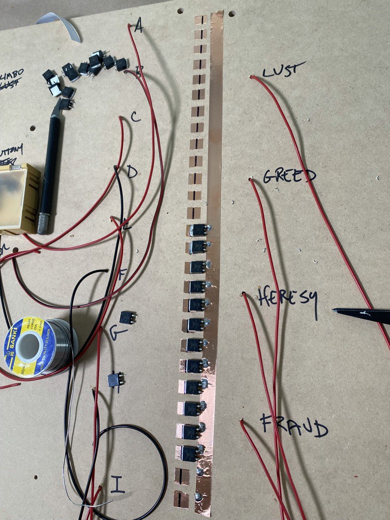
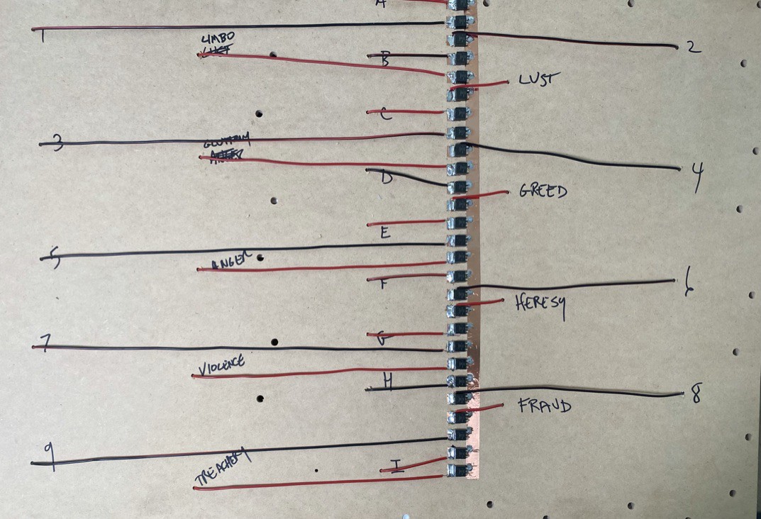
3Flip It Over & Wire It Up!
Use copper foil tape on the backside of the solid MDF backer where the LEDs are attached on the opposite side. I love this construction technique, it was fun making this! Lay the foil down to create buses and pads, almost like making a giant PCB. Solder the MOSFETs to the copper foil tape, using the long piece as a common ground bus on the MOSFET source & individual pads for the MOSFET drains. Prior to putting the MOSFETs down I bent the gate pin upward so as to not touch the ground bus.
![]()
![]()
-
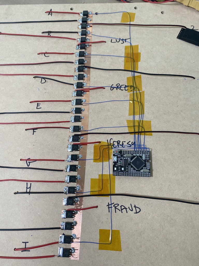
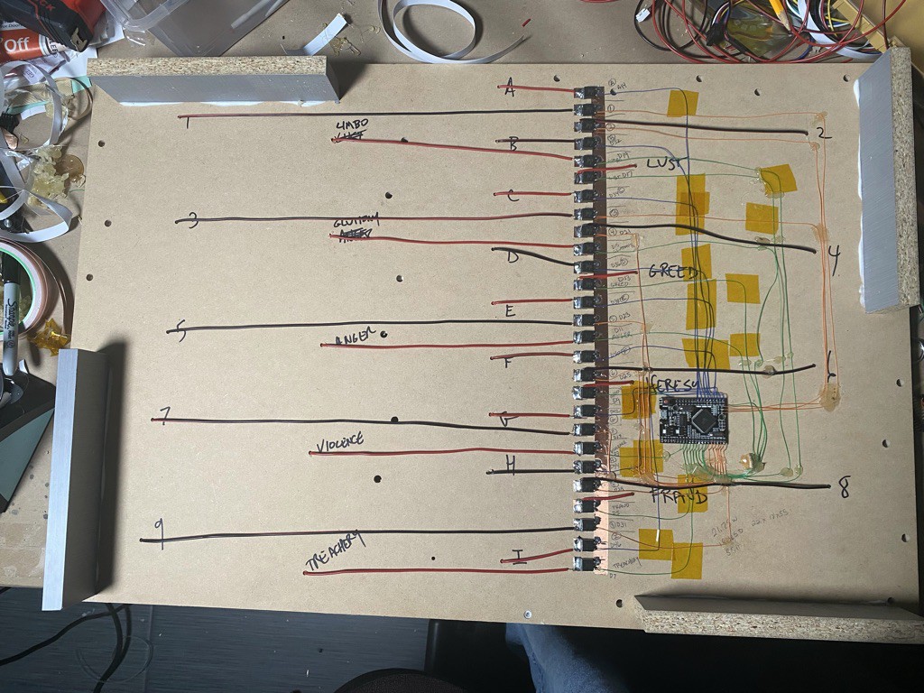
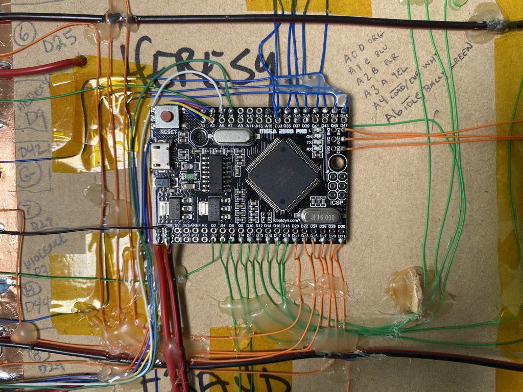
4Adding the Lighting Controller
Keep going with the wiring, adding in the Arduino Mega to control the light show:
![]()
![]()
![]()
Use Kynar tape to manage the wiring & hold it in place.
![]()
-
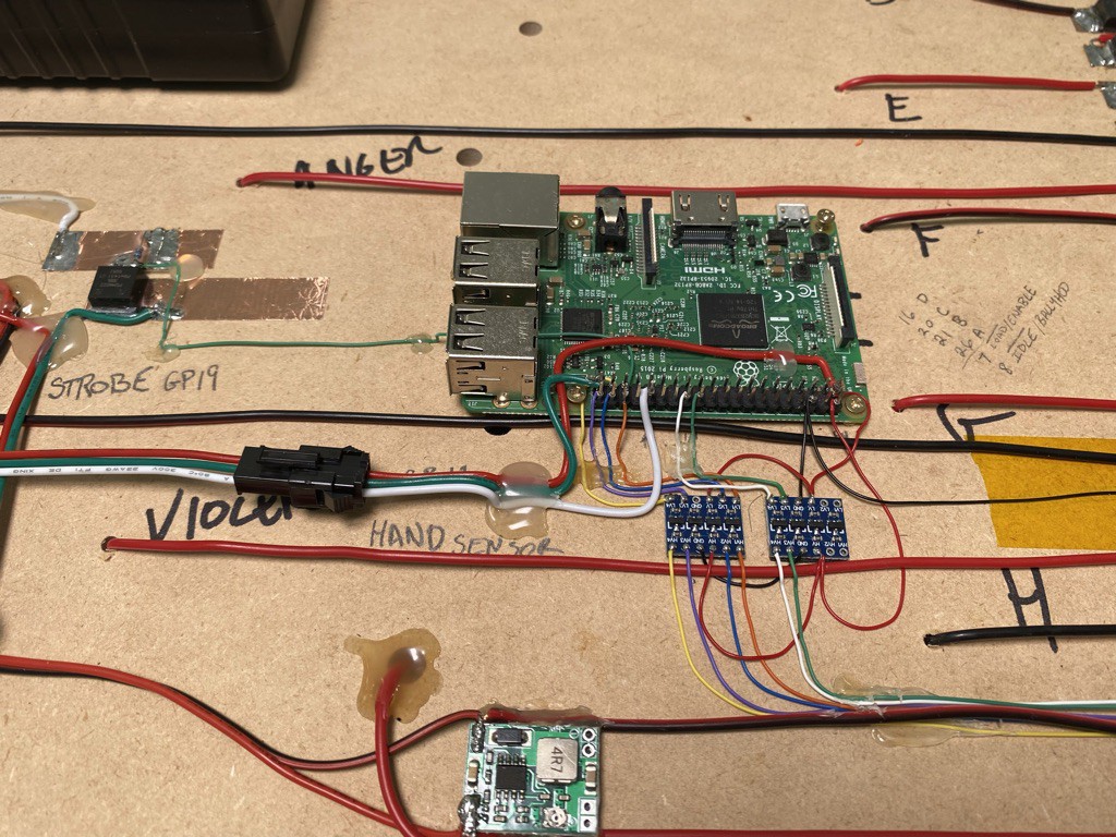
5Add the Pi!
![]()
This is the main Raspberry Pi 3 that controls the everything. Just below it are 3.3V<>5V level translators, and the green board below that is a 12V to 5V 3A buck converter to power the Pi from the battery & AC adapter.
![]()
Note the flowchart for operation! Shiloh Madsen will be referring to this a lot when writing the Python code for the Pi.
-
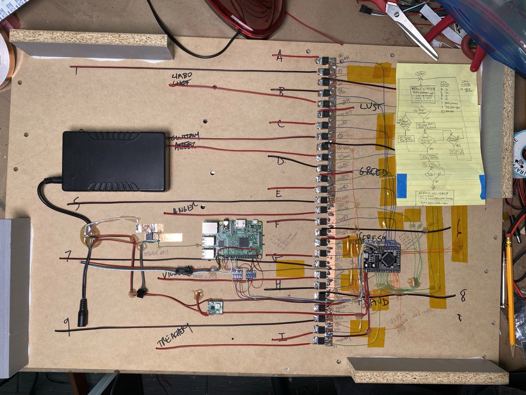
6Wrap It Up!
Almost all of the electronics in the cabinet are on the MDF board. When that is finished, the cabinet can be closed up & ready to program.
![]()
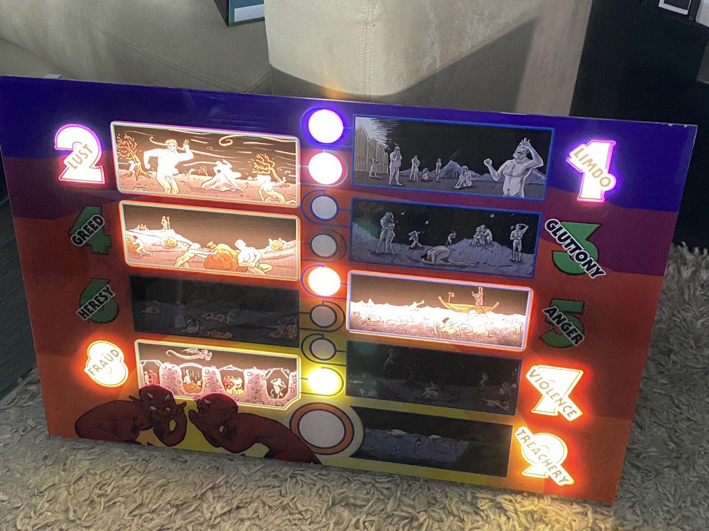
The Levels of Hell: Dante's Inferno 2.0
Like the Sorting Hat from Harry Potter, you are judged and assigned to your own Level of Hell!


Discussions
Become a Hackaday.io Member
Create an account to leave a comment. Already have an account? Log In.