 danjovic
I have experimented with some values for the bypass capacitors. Anything above 10uF should work fine. The blue trace was taken at the capacitor of the PNP transistor (the circuit's VCC) and the yellow trace is the video output, acquired on an empty line to be able to see the ripple along the whole line.
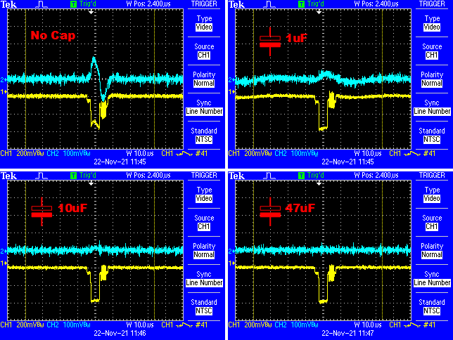
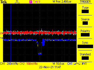
Any value above 10uF should do. Below is the overlap of voltage waveform using a 47uf (in Red) over the 10uF (in blue). Not much difference.
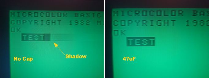
And the image below shows the shadow caused by the ripple of the Vcc voltage.
Discussions
Become a Hackaday.io Member
Create an account to leave a comment. Already have an account? Log In.