Luis
Luis-
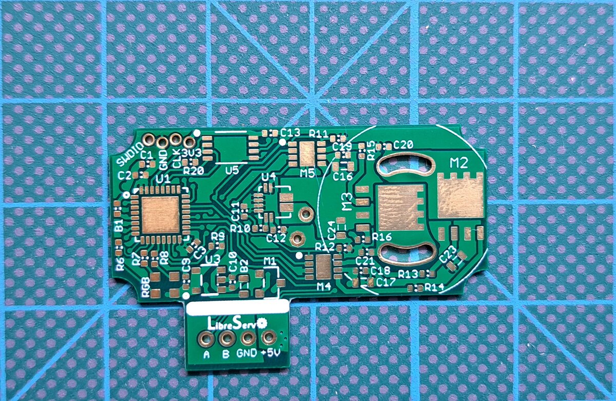
LibreServo v2.3.1. Release Version
05/24/2023 at 13:49 • 0 commentsLibreServo has finally reached the first final Hardware release (version 2.3.1)!
![party]()
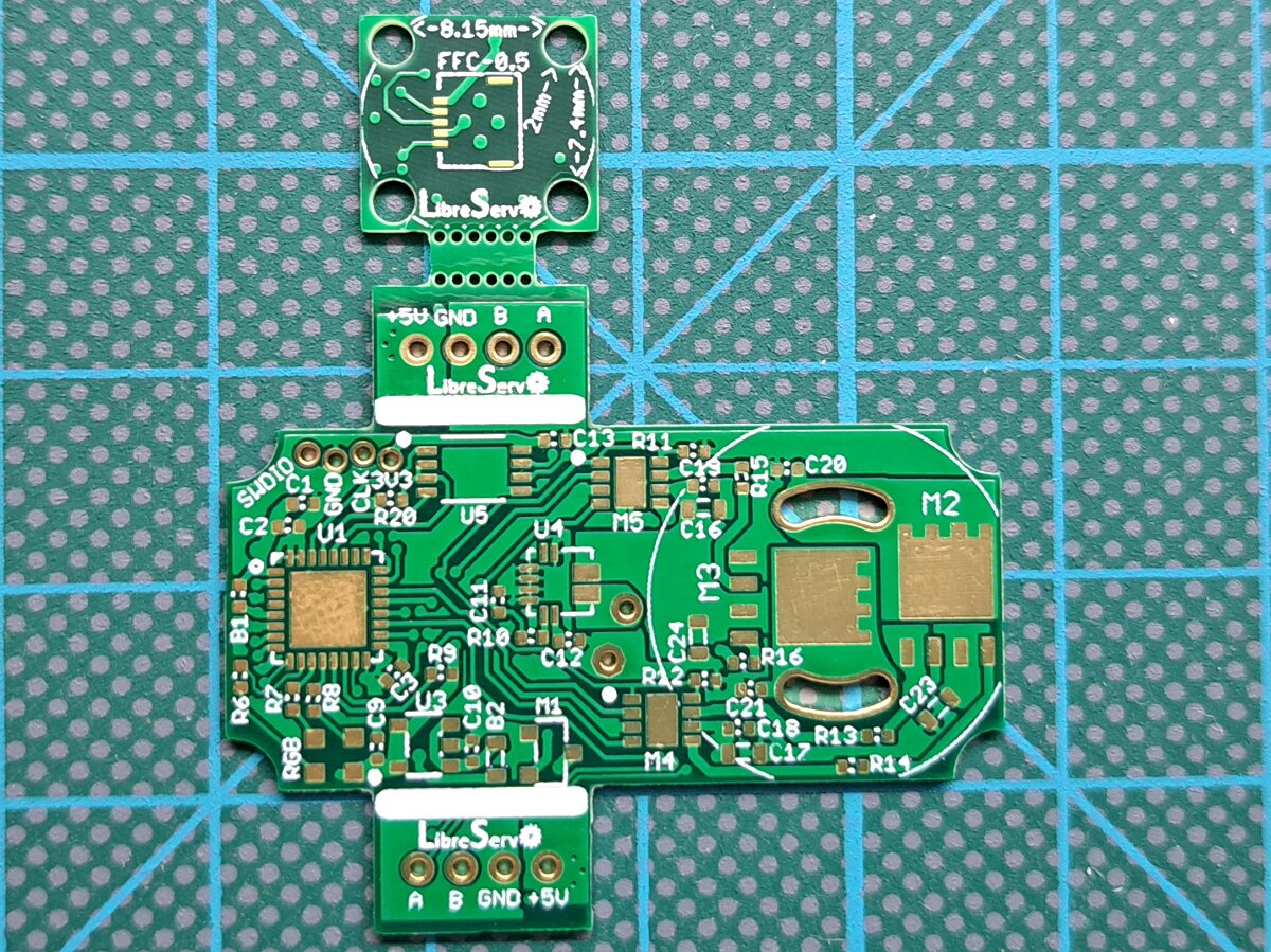
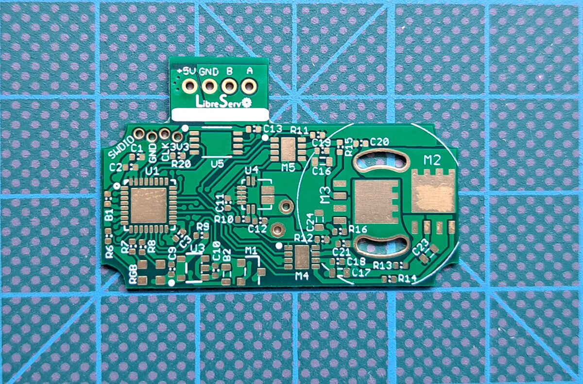
It has been a long road and there is still a long road ahead, but now on the software side. LibreServo will not stop here and later on there will come new projects that make use of LibreServo, like a possible 3D biped robot, but all of that will come in the future and all of it will be announced here so let's stop the guessing and talk about the now.In this version small modifications were made to the release candidate 2.3 as we saw in the changes in the final version article. In addition, all the promised versions of LibreServo were already made, version with two connectors and version with only one connector on one side to facilitate its use in any project and situation.
![LibreServo v2.3.1]()
![LibreServo v2.3.1]()
![LibreServo v2.3.1]()
The schematic has also been modified and it has been used to find and put in it alternative parts that are compatible with the PCB. In these times of scarcity it does not hurt to remember the stores that I personally use to find and buy components.
- Electronic components search engines
- Electronic components stores
Finally, not only the schematics have been uploaded to the LibreServo github, but also the gerber files so that you can have LibreServo produced directly (to produce LibreServo in 4 layers instead of 6, remove the .G2 and .G3 files from the compressed file). Except the encoder file, the rest are ready to use the Specify a location option in the Remove Order Number option offered by JLCPCB, the control number that JLCPCB puts is under the JST connector once the board is soldered, so it is perfect. In the encoder you will have to use the Yes option in Remove Order Number because it is such a small PCB that the JLCPCB number does not fit.
You can check also the schematics and more info in the article of the Realease Version of LibreServo
-
How well gold suits LibreServo!
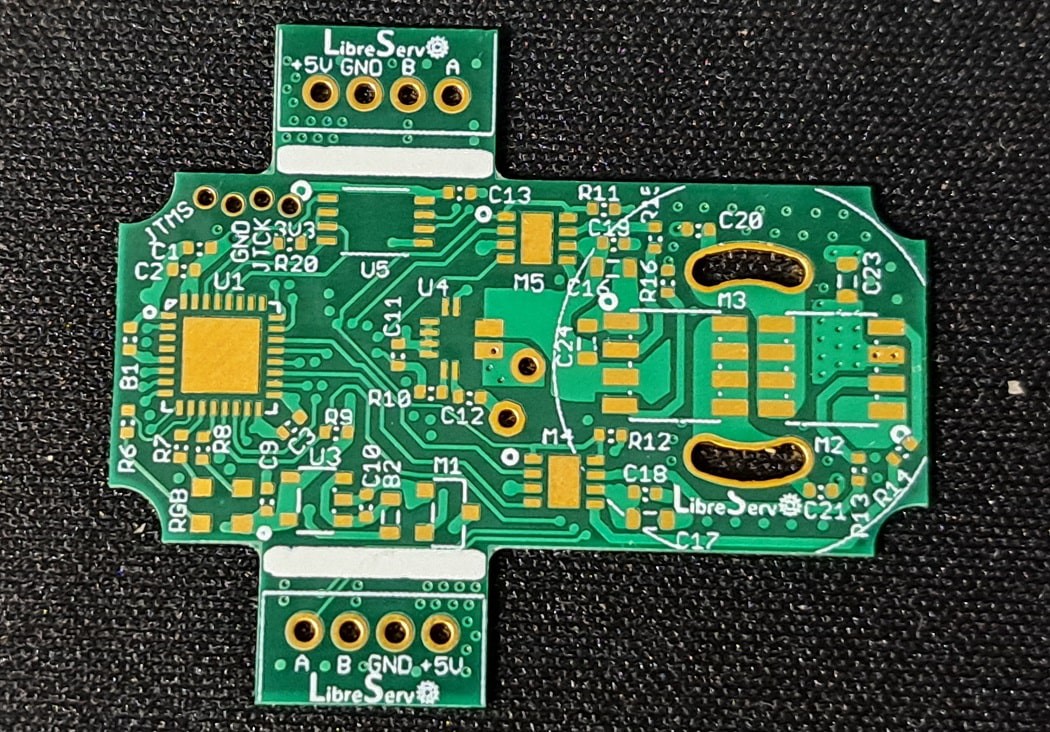
01/31/2023 at 14:33 • 0 commentsA few days ago I received the LibreServo boards I had ordered from JLCPCB. As I told you in the article of changes in LibreServo v2.1, the new version of LibreServo added two extra layers to reach the 6 layers and thus have the offer of JLCPCB and after receiving them and see them ... I only have words of absolute amazement.
The result is magnificent, not only the gold finish looks great in it 😎, the silkscreen itself is much better than when you order plates of four layers or less and the tracks filled with epoxy and covered in copper give an extraordinary result, not only at electrical/routing level and for soldering is a huge improvement, but also allows silkscreen printing on top of vias without any problem, which in LibreServo with the philosophy that has to point all the components to facilitate then when soldering, it comes great.
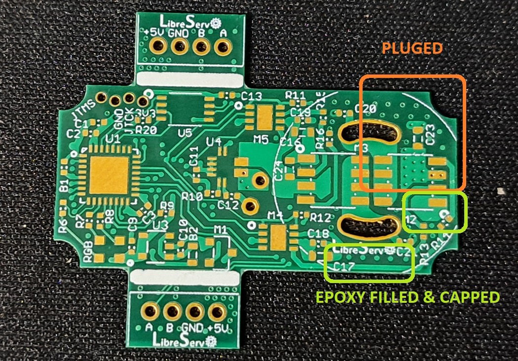
The only problem I have seen is that many vias have not been filled with epoxy and covered in copper. I have looked at the JLCPCB website and you have to indicate exprocess that you want to fill all the vias, which I did not do and that's why many arrived well, and many others as normal vias.
![]()
![]()
-
How to properly tune a PID
01/20/2023 at 10:18 • 0 commentsThis article comes to summarize the fantastic video that Peter Harrison made a few days ago on YouTube about the simplest and most effective way to tune a PID in a few minutes instead of days. I followed that video to tune the LibreServo PID and the results were amazing.
There are hundreds of guides on the Internet on how to adjust a PID and they can all be summarized in the following simple steps:
- Set KD and KI to zero and increase KP until the system corrects the error and starts oscillating. That would be the maximum KP
- Increase KD until the KP oscillation stops.
- Increase KI slightly so that the system fully corrects the error.
They seem like three simple and quick steps, but the reality is that in the end it becomes a sort of trying to guess the constants and after hundreds of tests and hours, if you are lucky, you get a relatively stable PID. It is a rather cumbersome task that rarely achieves a completely satisfactory result.
Let's forget about all that and try to obtain KP and KD mathematically. KI in a dynamic system is not necessary on most occasions and introduces more disadvantages than advantages, so we will forget about it for now. From now on, although I talk about a PID, I am really referring to a PD.
-
LibreServo v2.1 changes
01/20/2023 at 10:15 • 0 commentsIn the previous article on how to tune a PID, you can see how LibreServo is already fully operational. All the collected data you see in the graphs are data returned by LibreServo and the movements in the video are also real LibreServo movements. With this I want to say that LibreServo is already very close to a final and mature version of the project, at least in the hardware part, since in the software part there is always room for adding features and improving those already present.
With all the above said, I have made a new version of the hardware improving the little things that I have been seeing in the last months. Although at first glance it is not noticeable, changes and tweaks have been made throughout the board:
- More space has been given between the connectors (the PCB has been "widened" by 1.2mm), so that it fits correctly into the servomotors.
- Space has been given in the four corners to be able to reinforce the cover of the servomotor that has been designed in 3D. In the previous version I was limited by space and if the servomotor cover was screwed on tightly, it would crack in the screw area.
- JLCPCB has come out with a VERY AGGRESSIVE offer for 6 and 8 layer boards, so aggressive that it is cheaper than the 4 layer even though it includes ENIG finish (gold finish), epoxy filled vias and tin capped... all for $2 instead of $63 which would be their already low price. This is almost certainly a one-time offer. Even so, I have modified LibreServo to 6 layers, but maintaining full compatibility on 4 layers. When generating the Gerber files, just remove the two central layers, simple. The biggest benefit that is achieved with the two extra layers in LibreServo is that the flow through LibreServo to other LibreServo is more efficient, something that if a LibreServo is intended to hang more than three LibreServos would be something to value.
- We have tried to improve the routing of several components, use polygons where possible and improved the use of tracks.
- All the texts on the board have been tweaked.
- The LibreServo schematic has been reworked to meet certain standards.
Not content with that, and even though I have already ordered the new boards, I already have three other small changes that I will make soon to round the LibreServo design and make it the final design (I hope):
- I will change the oscillator to a 33% more compact, cheaper and more accurate version.
- I will change the order of the FFT cable between the main board and the AEAT-8800 sensor to give it a little more noise immunity.
- I will connect the exposed pad of the STM32F30X to ground, something that when I started with LibreServo ST indicated not to do, but now it has rectified and indicates that it is advisable... ST stuff 🤷
Finally, in the software part, the FP function has been added to find out the direction of rotation of the servomotor. The LibreServo Commands article has been updated.
-
LibreServo v2 Schematics
06/18/2022 at 16:38 • 0 commentsThe schematics are exactly the same with which I made the LibreServo v2 PCBs but with the texts corrected in position so they read better.
In previous posts as you can read in the article of the first LibreServo test board and in the conclusions of the second LibreServo test-board, the LibreServo changes were massive in each and every aspect. Virtually every component was overhauled and moved to a two PCB, four-layer design.
The result is as seen below, in addition, I have uploaded the design files to the LibreServo Github in the PCB folder.
An interactive version of the photos is available on the LibreServo website.

LibreServo v2 Schematic 
Top & Bottom 
Top 
Bottom 
Middle Bottom 
Middle Top -
New version of the 3D encoder parts
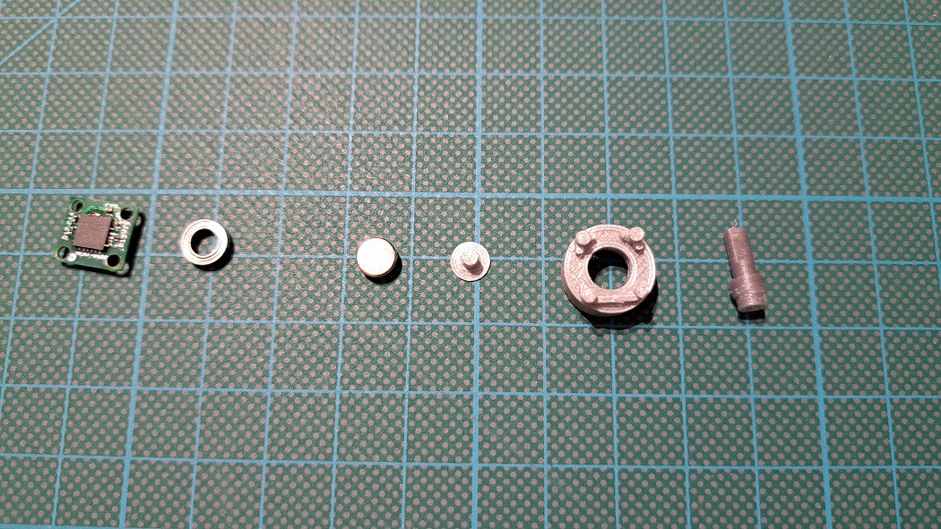
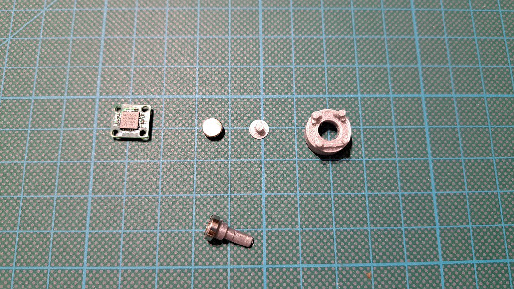
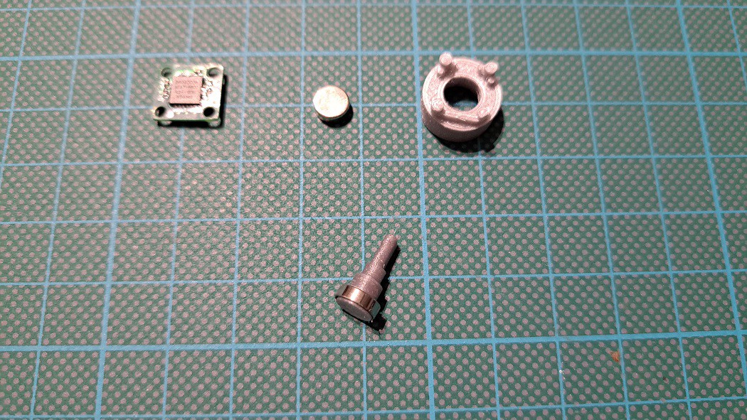
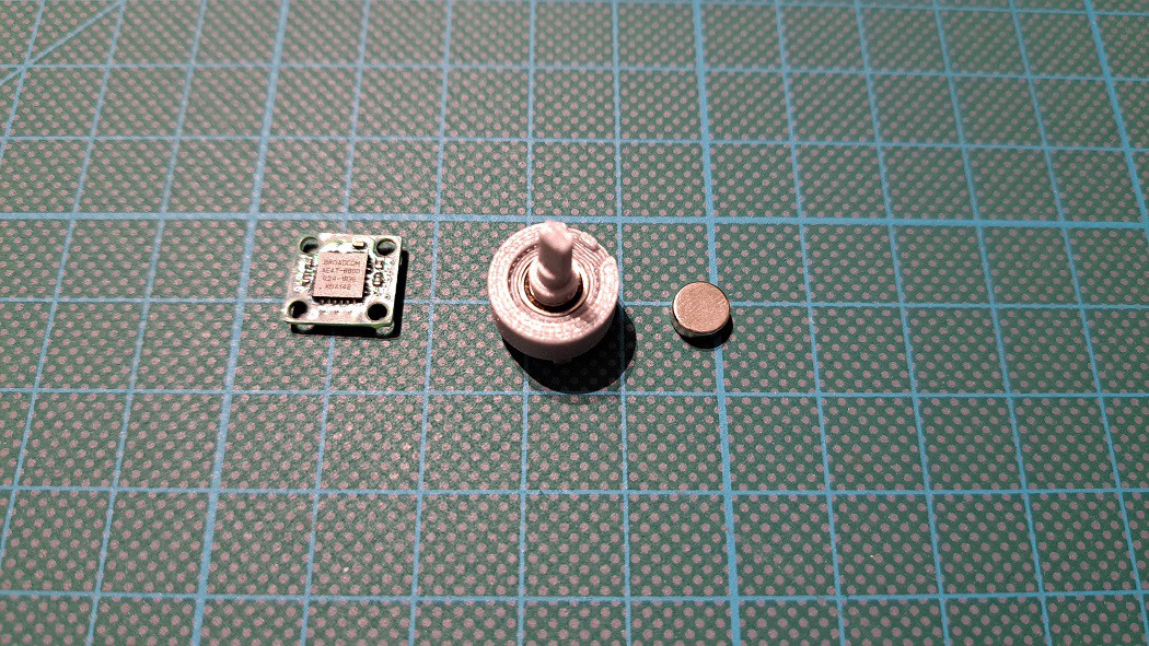
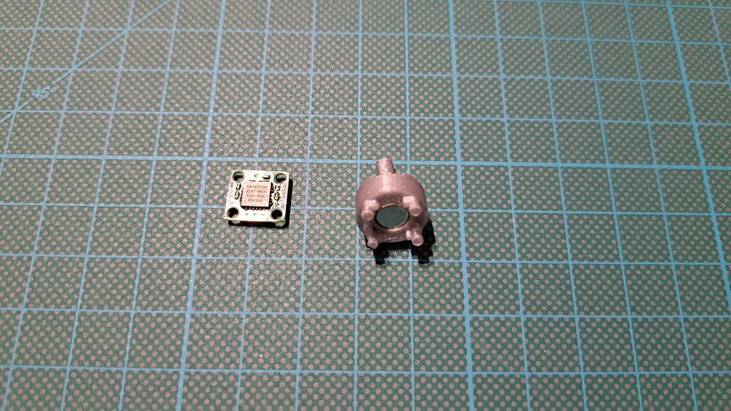
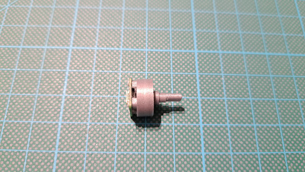
06/12/2022 at 22:30 • 0 commentsTo know the position of the servomotor axis, LibreServo uses the AEAT-8800 16-bit encoder. This encoder replaces the potentiometer that the servomotors have and with it we get much more precision and allows the servomotor to rotate 360 degrees.
To achieve this, LibreServo makes use of a tiny 10.2x11.2 mm PCB to which a 3D printed part of the same size and shape as the original potentiometer is attached. This 3D printed part consists of 3 small parts, a 4x7x2mm bearing and a small 6x2.5mm diametrically magnetized magnet. Only a glue point is needed to fix the magnet. The rest of the parts, bearing and PCB are designed to be snap-fitted and fixed.
With the first release of the LibreServo software, the 3D parts have also been updated. The .stl is uploaded to the Libreservo github in the 3D folder. The parts are designed to be printed with 0.1mm layers.
LibreServo encoder assembly video
![]()
![]()
![]()
![]()
![]()
![]()
-
LibreServo commands (part two)
06/06/2022 at 06:23 • 0 commentsI have spent a lot of time on the command part of LibreServo and I think it is one of the most important parts of the project, it is how LibreServo is presented to the user. It offers a flexibility and possibilities that I have never seen in any manufacturer.
The documentation of the commands will be divided into two articles, this article is more focused on examples and explanation of execution and the other article is focused on the description of LibreServo commands.
LibreServo has a task manager for the high-priority engine management part and a separate low-priority task manager for sending data to the user only (commands GX). This must be taken into account since the order and timing will be independent between the commands to receive data and the rest of the commands.
All commands start with the character 'S' and at least one servomotor number and end with ';'. Commands can be chained with the character '|' so that all commands are treated together as a block.
This article will be divided into the following topics:
- Servomotor Selection
- Command chaining
- Immediate commands [ ! ]
- CRC check
- Task managers and command timing
- Recovery mode
Servomotor Selection
All commands start with the character 'S' followed by at least one servomotor ID. The ID of a servo motor ranges from 1 to 255 (default is 1). LibreServo allows sending the same command to different servomotors at the same time. The '-' character indicates a range and the ',' character indicates independent servomotor IDs. For example, the commandS1,3,4,10-20M1000; means that servomotors with ID 1, 3, 4 and all with ID between 10 and 20 (both included) should move to position 1000. In addition, ID 0 is reserved (it is for broadcast) and any command sent to ID 0 will be like sending the command to all servomotors regardless of their actual ID.
Example:
S5MW500|S0M12000:1000; All servomotors will move to position 12000 in 1000 milliseconds, but servomotor 5 after a 500ms delay. S2,5,10-14,6M2000:500; Servomotors 2, 5, 6, 10, 11, 12, 13 and 14 will move to position 2000 in 500 milliseconds Command chaining
As we have seen, all commands start with the character 'S' and at least one servomotor number and end with ';'. You can chain commands with the '|' character so that all commands are treated together as a block. This is very useful for many reasons, one of the main ones being that until LibreServo sees the ';' character it doesn't start executing, so if you want different servomotors to execute different commands but want to make sure they all start moving at the same time, sending all the commands in one command is the way to make sure they start at the same time. Also, it is useful to send the variable reading commands along with the rest of the commands.
Example:
S1L255:0:0|S1T1567:300:100|S1T1567:10:0|S1T1567:300:100; Chain a series of Tone and LED commands, it can be the start of a song S2M1000:500|S3M2000:1000|S2M500:500; Servomotor 2 will move to 1000 in 500ms and then to 500 in 500ms while servomotor 3 moves to 2000 in 1000ms S2M1000:500|S2Gs13,11:500:1; Servomotor 2 will move at 1000 in 500ms and will report every millisecond its position and current consumption for viewing on the Serial Plotter of the Arduino, for example Immediate commands [ ! ]
Another unique feature of LibreServo is immediate or priority commands. A command can be sent as immediate with the '!' character before ';' or '|'. To take effect, it must be the first command for that servo motor that is sent, if it is sent with more chained commands, the one that is marked as immediate. An immediate command causes the execution of the command being executed to be aborted and clears all other commands in the task manager. An immediate command from the variable reading group (GX) does not affect the other commands as it is in a separate task manager, the same as the other immediate commands does not affect the variable reading commands.
Example:
S3M2000:200!; Servomotor 3 stops the command it was doing and clears all commands from its task manager, then moves to position 2000 in 200ms S2M1000:500|S3M2000:1000!|S2M500:500!|S3M500:1000; Servomotor 2 will NOT receive the commands as immediate because '!' is in its second command, while servomotor 3 will, since it is its first command in the command chain S2M1000:500!|S2Gs13,11:100:5; Servomotor 2 will receive an immediate command, but it does not affect the task manager of the Gs command, so if it was already executing a GX command, it will not execute the new Gs command at the same time as the new immediate motion command S2M1000:500!|S2Gs13,11:100:5!; This would be the proper way to make sure that the servo motor stops doing whatever it was doing in both task managers and executes our commands as a priority Comprobación CRC
The CRC check is used to make sure that the command received by LibreServo is correct and that no characters have changed during the serial (RS485) transmission. By default CRC checking is enabled in LibreServo but optionally (uso_crc = 2), this means that if you send a command with CRC checking LibreServo will accept it (and if the CRC checking is wrong, it will not execute the command), but if you send commands without CRC checking LibreServo will also accept them (if the command is correct, of course). Of course, you can modify the variable 117 (uso_crc) to make the use of CRC mandatory or to not accept any command with CRC.
By default the CRC check that is done is called CRC-16/AUG-CCITT. The following online crc calculator is recommended for making checks.
The CRC code is sent at the end of the command in hexadecimal format, just before the ';' character and after the '!' character if any. It is preceded by the '#' character and takes into account the entire command up to just the character before the '#' character.
Example:
S1G5#E0CF; The CRC code is sent as hexadecimal. In this case it would be E0CF S1M1000:1000|S1GW20|S1Gs16,21,9:1100:1|S3MF#DD7B; Of course in chained commands the CRC code works in the same way and takes into account the complete command, even if parts are for different servomotors Task managers and command timing
In LibreServo there are two task managers. One is the main one for all commands and the other one is exclusive only for variable reading commands. The variable writing and saving commands also go in the main task manager.
Both task managers are like FIFO queues, the first command that comes in is the first to be executed. The task manager just executes one command after another waiting for one command to finish to start executing the next command. Both task managers run at 1KHz, so the minimum execution time for any command is 1ms.
There are two major differences between task managers. The main has a capacity of 100 commands and runs at high priority, while the variable reading task manager has a capacity of 15 commands and runs at low priority. Low priority indicates that its execution is not guaranteed to be exactly every millisecond. It is possible that there may be small variations depending on other interrupts within LibreServo. When we talk about small variations, we always talk about variations of less than a millisecond, so it should not really affect us in the least.
Having these concepts clear, let's see some examples to see what is the order and timing of execution:
Example:
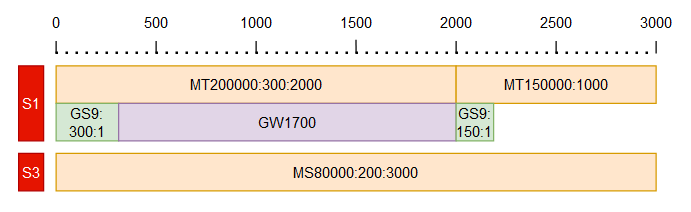
S1MT200000:300:2000|S1MT150000:1000|S1GS9:300:1|S3MS80000:200:3000|S1GW1700|S1GS9:150:1; ![]()
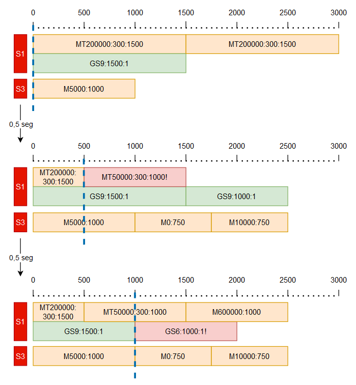
In this example we see a command composed of several subcommands. Although the commands of servo motor 3 is interleaved, each servo motor takes only its commands. We also see how the variable reading commands work in another queue S1MT200000:300:1500|S1MT100000:300:1500|S1GS9:1500:1|S3M5000:1000;
[WAIT 0,5 seg.]
S3M0:750|S3M10000:750!|S1M50000:1000!|S1GS9:1000:1;
[WAIT 0,5 seg.]
S1M600000:1000|S1GS6:1000:1;![]()
In this example we see how '!' works. We see how it only affects each specific queue of each servomotor. The commands with preference '!' must be the first command for that servomotor of its queue, as we see with servomotor 3, in the second set of commands does not apply '!' because it is not the first command Recovery mode
There are several reasons why we could lose communication with LibreServo. If we do not know the servo motor ID, we just have to send a command to the servo with ID 0 (remember that all servo motors respond to that ID) and pick up or change the servo motor ID. But, if we do not know the serial port speed, or we have saved a speed that is higher than what we can use, for example, arduino only reaches 115200bps but LibreServo is able to communicate at 9Mbps, in that case there is the possibility of forcing LibreServo to reconfigure with the default configuration.
To get LibreServo into recovery mode, we must start LibreServo with pin A of the RS485 port connected to ground and B directly to VCC. WARNING! VCC should never be higher than 13V in this operation because the RS485 chip does not support higher voltages on its input pins. If pins A and B are as mentioned above when turning on LibreServo, LibreServo starts flashing the white LED faster and faster until after 6 seconds, if A and B have not changed value at any time, it reconfigures and saves the default configuration in flash. Now we can turn LibreServo off or continue using it since it will have the default configuration loaded.
-
LibreServo commands (part one)
06/05/2022 at 17:52 • 0 commentsI have spent a lot of time on the command part of LibreServo and I think it is one of the most important parts of the project, it is how LibreServo is presented to the user. It offers a flexibility and possibilities that I have never seen in any manufacturer.
The documentation of the commands I will divide it in two articles, this article is more focused on the description of the commands and the second part is focused on examples and explanation of execution in LibreServo.
The LibreServo commands are as follows:
- Motion commands
- Linear Motion [M]
- Trapezoidal Motion [MT]
- Trapezoidal Motion 50% [Mt]
- Accelerated trapezoidal Motion [MA]
- Sine Motion [MS]
- Sine Motion 50% [Ms]
- Hermitic Motion [MH]
- Continuous Motion [MC]
- Continuous Trapezoidal Motion [MCT]
- Continuous Sine Motion [MCS]
- Hermitic Continuous Movement [MCH]
- Motion PWM [MP]
- Free Motor [MF]
- Motor Wait [MW]
- Light and sound commands
- Variable read and write commands
Motion commands
These are specific commands for the movement and control of the servomotor. The different motions and their curves are explained in more detail in the article on motion curves.
Linear motion [M]
- S12M12000[:1000]
The notation we see for 12000[:1000] indicates that the M command forces one parameter to be passed, but the second parameter is optional. It also tells us that the ':' character is used to separate the parameters. This notation is used for all other commands.
Returning to the command, the M command is a command in which the servomotor moves at constant speed to the end position.
param1: the first parameter indicates the position we want to go to (a 360 degree turn is 65,535). Range: -2.147.483.646, +2.147.483.647
param2 (optional): the second parameter indicates in milliseconds, ms, the time in which the movement should be completed, if no time is indicated LibreServo will try to arrive as soon as possible. Range: 0, +2.147.483.647Example:
S12M12000:1000; Servomotor 12 shall move to position 12000 in 1000 ms (1 second). Trapezoidal motion [MT]
- S12MT12000[:150]:1000;
The MT command is a constant acceleration and deceleration motion calculated based on a fixed acceleration duration.
param1: final position. Range: -2.147.483.646, +2.147.483.647
param2 (opcional): acceleration and deceleration time in ms. If not specified, the default value stored in flash (t_ramp_t) is taken. If the acceleration and deceleration time is greater than the total movement time, they are reduced to fit into the total movement time. Range: 0, +2.147.483.647
param3: total movement time. Range: 0, +2.147.483.647Example:
S12MT-8000:1000; Servomotor 12 shall move to position -8000 in 1000ms. The ramp time shall be the one that is at t_ramp_t S12MT-8000:150:1000; Servomotor 12 shall move to position -8000 in 1000ms. The ramp time shall be 150ms Trapezoidal motion 50% [Mt]
- S12Mt12000:1000;
It is the same as MT, but the acceleration time will be half of the total movement time and the deceleration time the other half.
param1: final position. Range: -2.147.483.646, +2.147.483.647
param2: total movement time. Range: 0, +2.147.483.647Example:
S12MT-8000:1000; Servomotor 12 shall move to position -8000 in 1000ms. The ramp time shall be 500ms (500*2 = 1000) Accelerated trapezoidal motion [MA]
- S12MA12000[:150]:1000;
It is a trapezoidal movement, but instead of indicating the acceleration time, you indicate the desired acceleration and LibreServo calculates the required acceleration and deceleration time.
param1: final position. Range: -2.147.483.646, +2.147.483.647
param2 (opcional): Aceleración y desaceleración de la rampa. If not specified, the default value stored in flash (a_ramp_t) is taken. If the indicated acceleration does not reach the destination, a linear movement will be made. Range: 0, +2.147.483.647
param3: total movement time. Range: 0, +2.147.483.647Example:
S12MA-8000:1000; The servomotor 12 shall move to position -8000 in 1000ms. The acceleration of the ramp shall be the one that is at a_ramp_t S12MA11000:125:1000; Servomotor 12 shall move to position -8000 in 1000ms. The acceleration of the ramp shall be 125 Sine Motion [MS]
- S12MS12000[:150]:1000;
The MS command produces a movement with variable acceleration and deceleration in the form of a sine, hence its name.
param1: final position. Range: -2.147.483.646, +2.147.483.647
param2 (opcional): acceleration and deceleration time in ms. If not specified, the default value stored in flash (t_ramp_s) is taken. If the acceleration and deceleration time is greater than the total movement time, they are reduced to fit into the total movement time. Range: 0, +2.147.483.647
param3: total movement time. Range: 0, +2.147.483.647Example:
S12MS50000:2000; Servomotor 12 shall move to position 50000 in 2000ms. The ramp time shall be the one at t_ramp_s S5MS50000:150:2000; Servomotor 5 shall move to position 50000 in 2000ms. The ramp time shall be 150ms Sine Motion 50% [Ms]
- S12Ms12000:1000;
It is the same as MS, but the acceleration time will be half of the total movement time and the deceleration time the other half.
param1: final position. Range: -2.147.483.646, +2.147.483.647
param2: total movement time. Range: 0, +2.147.483.647Example:
S8MT-8000:3000; Servomotor 8 shall move to position -8000 in 3000ms. The ramp time will be 1500ms (1500*2 = 3000) Hermitic Movement [MH]
- S12MH12000[:0][:8000][:0]:1000;
As a rule, all movements assume that the servomotor starts a motion from stop and ends stopped, but in this curve we indicate the starting point of movement, the initial speed, the end point and the final speed and LibreServo calculates the entire path. It is ideal for when we want to interrupt a movement and that the servomotor already starts from the speed in which it was, to make complex chained movements ... or to generate different curves to the previous movements.
param1 (opcional): initial position. If not specified, it is the position at the beginning of the movement. Range: -2.147.483.646, +2.147.483.647
param2 (opcional): initial velocity. If it is not specified, it is the one it had at the beginning of the movement. Range: -2.147.483.646, +2.147.483.647
param3: final position. Range: -2.147.483.646, +2.147.483.647
param4 (opicional): final velocity. If not specified, it is zero. Range: -2.147.483.646, +2.147.483.647
param5: total movement time. Range: 0, +2.147.483.647Example:
S7MH12000:1000; Servomotor 7 will move to position 12000 in 1000ms. The initial position and velocity of the movement will be the one just at the beginning of the curve. It also assumes that the final velocity we want will be zero S15MH5000:12000:1500; Servomotor 15 will move to position 12000 in 1500ms. The initial position is 5000, the initial velocity will be the one right at the beginning of the curve and the final one is assumed to be zero S3MH1300:0:-12000:-300:4000; Servomotor 3 will move to position -12000 in 4000ms. The initial position is 1300 with an initial velocity of zero and final velocity of -300 Continuous Motion [MC]
- S12MC65535[:1000]
Like Linear Motion, MC behaves in the same way but takes into account the speed of the servomotor and not its position.
param1: final speed at which we want to go (a 360 degree turn is 65,535, speed of one turn per second would be 65535). Range: -2.147.483.646, +2.147.483.647
param2 (opcional): the second parameter indicates in milliseconds, ms, the time in which the speed should be reached, if no time is indicated LibreServo will try to arrive as soon as possible. Range: 0, +2.147.483.647Example:
S9MC-131070:1000; Servomotor 9 should move -2 turns per second (65535*2 = 131070) in 1000 ms (1 second). Continuous Trapezoidal Motion [MCT]
- S12MCT65535[:150]:1000;
param1: final speed. Range: -2.147.483.646, +2.147.483.647
param2 (opcional): acceleration and deceleration time in ms. If not specified, the default value stored in flash (t_ramp_t) is taken. If the acceleration and deceleration time is greater than the total movement time, they are reduced to fit into the total movement time. Range: 0, +2.147.483.647
param3: total movement time. Range: 0, +2.147.483.647Example:
S5MCT-32767:1000; Servomotor 5 shall reach the speed of minus half a revolution per second in 1000ms. The ramp time shall be the one at t_ramp_t S4MCT-32767:150:1000; Servomotor 4 shall reach the speed of minus half a revolution per second in 1000ms. The ramp time shall be 150ms Continuous Sine Motion [MCS]
- S12MCS65535[:150]:1000;
param1: final speed. Range: -2.147.483.646, +2.147.483.647
param2 (opcional): acceleration and deceleration time in ms. If not specified, the default value stored in flash (t_ramp_s) is taken. If the acceleration and deceleration time is greater than the total movement time, they are reduced to fit into the total movement time. Range: 0, +2.147.483.647
param3: total movement time. Range: 0, +2.147.483.647Example:
S6MCS65535:2000; The servomotor 6 shall reach the speed of one revolution per second in 2000ms. The ramp time shall be the one at t_ramp_s S2MCS65535:150:2000; Servomotor 2 shall reach the speed of one revolution per second in 2000ms. The ramp time shall be 150ms Hermitic Continuous Movement [MCH]
- S12MCH12000[:0][:8000][:0]:1000;
In this command we pass the initial and final velocity of the movement as well as the initial and final acceleration that we want and LibreServo calculates the entire path. It is ideal for when we want to interrupt a movement and that the servomotor already starts from the speed in which it was, to make complex chained movements ... or to generate different curves to the previous movements.
param1 (opcional): initial velocity. If it is not specified, it is the one it had at the beginning of the movement. Range: -2.147.483.646, +2.147.483.647
param2 (opcional): initial acceleration. If it is not specified, it is the one it had at the beginning of the movement. Range: -2.147.483.646, +2.147.483.647
param3: final speed. Range: -2.147.483.646, +2.147.483.647
param4 (opicional): final acceleration. If not specified, it is zero. Range: -2.147.483.646, +2.147.483.647
param5: total movement time. Range: 0, +2.147.483.647Example:
S3MCH65535:1000; Servomotor 3 will reach the speed of one revolution per second in 1000ms. The initial velocity and acceleration of the motion will be whatever it is right at the start of the curve. It also assumes that the final velocity we want will be zero S7MCH65535:-32767:1500; The servomotor 7 will reach the speed of minus half a turn per second in 1500ms. The initial speed is one revolution per second, the initial acceleration will be the one just at the beginning of the curve and the final acceleration is assumed to be zero S16MCH0:10:131070:-300:4000; The servomotor 16 will reach the speed of two turns per second in 4000ms. The initial velocity is zero with an initial acceleration of 10 and final acceleration of -300 Motion PWM [MP]
- S12MP500[:1000];
To directly control the PWM of the motor, we use the command MP.
param1: PWM del motor. Range: -1800, +1800
param2 (optional): Time that the command will last. If we do not enter time, the command will end immediately but will leave the motor with the PWM we have entered. If time is entered, at the end of the time, the motor will stop.Example:
S12MP-500; Servomotor 12 will set a PWM of 500 with negative direction S10MP300:1000; Servomotor 10 will set a PWM of 300 for 1000ms Free Motor [MF]
- S12MF;
The MF command disables the motor. What it does is to turn off the H-bridge. As soon as another motion command arrives, the H-bridge is automatically enabled.
Example:
S14MF; Servomotor 14 disables the motor Motor Wait [MW]
- S12MW250;
The MW command functions as a Delay. It introduces a wait. It is useful for when we want to send from the same command several tasks that we want to be done separated in time and not one after the other.
param1: The milliseconds of waiting: Range: 0, +2.147.483.647Example:
S17MW500; Servomotor 17 waits 500ms Light and sound commands
LED RGB [L]
- S12L150:25:210;
The L command controls the color and intensity of the built-in LibreServo RGB LED. Theoretically it could display any color we want.
param1: Red color intensity. Range: 0, +255
param2: Green color intensity. Range: 0, +255
param3: Blue color intensity. Range: 0, +255Example:
S7L150:25:210; The LED of the servomotor 7 turns lilac LED Rainbow [LR]
- S12LR;
The LR command instructs the LED to start rotating through the colors automatically.
Example:
S9LR; The servo motor LED 9 starts to rotate in colors and intensities automatically Tone [T]
- S12T2093:200:50;
The T command attempts to generate a tone using the servo motor itself. No speaker is needed to generate your favorite music! It is recommended to use high frequencies, above 1500Hz, for best performance, sixth or seventh octave onwards depending on each servomotor. At low frequencies it may not sound and instead vibrate the entire servomotor.
param1: Frequency of the tone/note. It is recommended to use frequencies above the sixth musical octave. Range: 0, +2.147.483.647
param2: Note length in milliseconds. Range: 0, +2.147.483.647
param3: Note amplitude, its volume. Range: 0, +100Example:
S12T3136:200:50; Servomotor 12 generates a SOL6 tone lasting 200ms with an amplitude of 50% ![Frecuencia notas musicales]() Frequency of musical notes @ciudadpentagrama
Frequency of musical notes @ciudadpentagrama
Variable read and write commands
Variable read commands are executed from a separate task manager. Within the variables to be recovered, there are RAM variables that are read-only and are not saved after LibreServo is turned off, and there are FLASH variables, which are read and write variables that can be modified and/or saved so that the next time LibreServo is started it will keep the value that we have given it.
The variables are:
ID Name R/W Definition Default value 0 Temp_interna R Temperature in degrees (x10) as measured internally in the microcontroller 1 Temp_externa R Temperature in degrees (x10) measured externally on NTC temperature sensor 2 Temp_interna_raw R Direct readout (12 bits) from internal temperature sensor to microcontroller 3 Temp_interna_kalman R Internal temperature sensor reading to the microcontroller after Kalman filtering 4 Temp_externa_raw R Direct reading (12 bits) of the external temperature sensor NTC 5 Temp_externa_kalman R External NTC temperature sensor reading after Kalman filter 6 Voltage R Voltage, supply voltage of LibreServo (x100) 7 Voltage_raw R Readout (12 bits) of the power supply voltage 8 Voltage_kalman R Power supply voltage reading after Kalman filtering 9 Corriente R Current consumed by the servomotor in mA 10 Corriente_raw R Readout (12 bits) of the current consumed by the servomotor 11 Corriente_kalman R Current reading after Kalman filter 12 Encoder_raw R Encoder position reading (16 bits) 13 Encoder_kalman R Encoder position reading after Kalman filter 14 Velocidad_enc R Servomotor speed calculated from encoder position 15 Aceleracion_enc R Servomotor acceleration calculated from encoder position 16 Velocidad_sim R Servomotor speed calculated with the desired position of the servomotor 17 Aceleracion_sim R Servomotor acceleration calculated with the desired position of the servomotor 18 Posicion_objetivo R Position LibreServo is marking 19 Error R Difference between Posicion_objetivo and encoder reading after Kalman filter (Encoder_kalman) 20 DError R Differential error (PID) 21 PDTerm R PD Term of the PID 22 Iterm R Integral Term of the PID 23 PWM R Motor PWM 24 PWM_pre R PWM desired before looking to see if current draw is excessive 99 Version_LS R LibreServo internal version 100 ID Servomotor R/W ID of the servomotor, through which it will listen for commands 1 101 q_corriente R/W Current process uncertainty (x1000) (Kalman) 1200 102 q_temp_ext R/W NTC temperature process uncertainty (x1000) (Kalman) 1200 103 q_temp_int R/W Uncertainty process internal temperature STM32 (x1000) (Kalman) 1200 104 q_volts R/W Process voltage uncertainty (x1000) (Kalman) 1200 105 q_encoder R/W Uncertainty encoder process (x1000) (Kalman) 1200 106 varianza_corriente R/W Current variance (x1000) (Kalman) 1000 107 varianza_temp_ext R/W NTC temperature variance (x1000) (Kalman) 2500 108 varianza_temp_int R/W Variance internal temperature STM32 (x1000) (Kalman) 150 109 varianza_volts R/W Voltage variance (x1000) (Kalman) 150 110 varianza_encoder R/W Encoder variance (x1000) (Kalman) 5000 111 vel_serie R/W Serial port speed 115200 112 corte_temp_ext R/W Temperature in degrees (x10) at the NTC stopping the motor 800 113 corte_temp_int R/W Internal temperature in degrees (x10) of the STM32 stopping the motor 800 114 corte_volts_alto R/W Voltage (x100) which, if exceeded, stops the motor 1600 115 corte_volts_bajo R/W Voltage (x100) which, if not exceeded, stops the motor 450 116 corte_corriente R/W Maximum current in mA. Torque control 7000 117 uso_crc R/W CRC Use (0=False, 1=True, 2=Both) 2 118 CRC_START_CCITT R/W CRC initial value 0x1D0F 119 CRC_POLY_CCITT R/W CRC polynomial 0x1021 120 K_P_LS R/W Constant P PID servomotor mode 200 121 K_D_LS R/W Constant D PID servomotor mode 1000 122 K_I_LS R/W Constant I PID servomotor mode 170 123 K_P_M R/W Constant P PID motor mode 200 124 K_D_M R/W Constant D PID motor mode 1000 125 K_I_M R/W Constant I PID motor mode 170 126 offset_corriente R/W Current offset (x1000) (0-222 -> -1000 - +1000) 111 127 offset_temp_int R/W Internal temperature offset (x10) (0-300 -> -150 - +150) 150 128 offset_temp_ext R/W NTC temperature offset (x10) (0-300 -> -150 - +150) 150 129 envio_si_leo R/W Send data over the serial port if I read other data over the serial port (0=False, 1=True, 2=True cancelar sólo el comando de envío actual) 2 130 saludo_inicial R/W Initial greeting (0=False, 1=True) 1 131 min_posicion R/W Minimum position limit (0-4294967294 -> -2147483647 - +2147483647) 2147483647 132 max_posicion R/W Maximum position limit (0-4294967294 -> -2147483647 - +2147483647) 2147483647 133 limit_posicion R/W Use position limits (0=False, 1=True) 0 134 t_ramp_t R/W Default time trapezoidal ramp 200 135 t_ramp_s R/W Default time sine ramp 200 136 a_ramp_t R/W Trapezoidal ramp default acceleration 100 137 deadband R/W Deadband 5 GET [G]
- S12G116;
The G command asks LibreServo for an internal parameter/variable that it will return over the serial port. The G command like the rest of the GX commands go in a separate task manager from the main one.
param1: ID of the variable whose value we want to see.Example:
S11G13; Read servomotor position 11 Get Several [GS]
- S12GS5[,7,8,100,102]:10:500;
The GS command returns not only one variable, but several variables that we want (up to a maximum of 15). In addition, it can be programmed to return the values every X milliseconds.
param1: Parameter where we indicate the ID or IDs of the variables to be read separated by commas ','. Range: 0, +137.
param2: Number of times we want to send us the value of the variables. Range: 1, +2.147.483.647
param3: Every how many milliseconds we want to send us the value of variables. Range: 1, +2.147.483.647Example:
S12GS9,23:1000:1; Read from servomotor 12 the current consumption and PWM of the motor 1000 times with a time between readings of 1 millisecond. It will be one second sending data S5GS0,1:1,1; Read servomotor 5 temperatures. Only sent once Get Several with Header [Gs]
- S12Gs5[,7,8,100,102]:10:500;
The Gs command is the same as the GS command with a difference, it sends us at first a line with the name of all the variables we want separated by commas, this is very useful to get a .csv file output, or to see the variables drawn in the Serial Plotter of Arduino. The Gs command returns not only one variable, but several variables that we want (up to a maximum of 15). In addition, it can be programmed to return the values every X milliseconds.
param1: Parameter where we indicate the ID or IDs of the variables to be read separated by commas ','. Range: 0, +137.
param2: Number of times we want to send us the value of the variables. Range: 1, +2.147.483.647
param3: Every how many milliseconds we want to send us the value of the variables. Range: 1, +2.147.483.647Example:
S3Gs9,23:1000:1; Read from servomotor 3 the current consumption and PWM of the motor 1000 times with a time between readings of 1 millisecond. It will spend one second sending data. Send an initial header line S9Gs0,1:1,1; Read servomotor 9 temperatures. Only to be sent once and with header Get Wait [GW]
- S12GW250;
The GW command works as a Delay. It introduces a wait in the task manager for reading variables. It is useful for when we want to start receiving data but after a wait to match some specific engine command.
param1: The milliseconds of waiting. Range: 0, +2.147.483.647Example:
S16GW500; Servomotor 16 waits 500ms in the task manager for reading variables Set [S]
- S12S111:9600;
With the S command we change the value of LibreServo variables that are writable.
param1: Variable ID to be modified. Range: 0, +137
param2: New variable value. Range: -2.147.483.646, +2.147.483.647Example:
S1S100:10 Change the servomotor ID 1 to 10 S10S111:9600 Changes the serial port speed [variable 111] of servo motor 10 to 9600 bps Save [SV]
- S12SV;
The SV command saves the current LibreServo configuration, the value of the modifiable variables, in the microcontroller Flash, so the configuration will not be lost when the servo motor is turned off.
Example:
S39SV; Saves the value of all modifiable variables of the servomotor 39 in Flash Reset variable [RV]
- S12RV116
The RV command returns the value of a variable to the value it has in flash. If the variable was saved just before with the SV command, the variable will have the same value in memory as in flash.
param1: Variable ID to be reset Range: 0, +137Example:
S23RV137; Returns the flash value of the servomotor 23 to the variable deadband Reset variable default value [Rv]
- S12Rv116
The Rv command returns the value of a variable to the default value specified in the table. And saves that variable in flash.
param1: Variable ID to be reset. Range: 0, +137Example:
S18Rv117; The variable 117 (uso_crc) of the servomotor 18, returns to its default value, 2 Reset Servo [RS]
- S12RS;
The RS command returns the value of all servomotor variables to the value they have in flash.
Example:
S10RS; The servomotor 10 returns the value in flash to all its variables Reset Servo default [Rs]
- S12Rs
The Rs command changes the value of all variables to their default value and saves it in flash.
Example:
S45Rs; The servomotor 45 returns the value of all its variables to their default value and saves them to flash - Motion commands
-
Updated LibreServo software (version v0.1)
06/05/2022 at 09:38 • 0 commentsAfter several months of work, LibreServo has finally reached version 0.1 in the software. What does this mean? It means that LibreServo is still in Beta version, but it is mature enough to present itself in society. This will be only the first of several entries that I will be uploading these days.
I have updated the Github of LibreServo with the latest files and I will try to keep it updated.
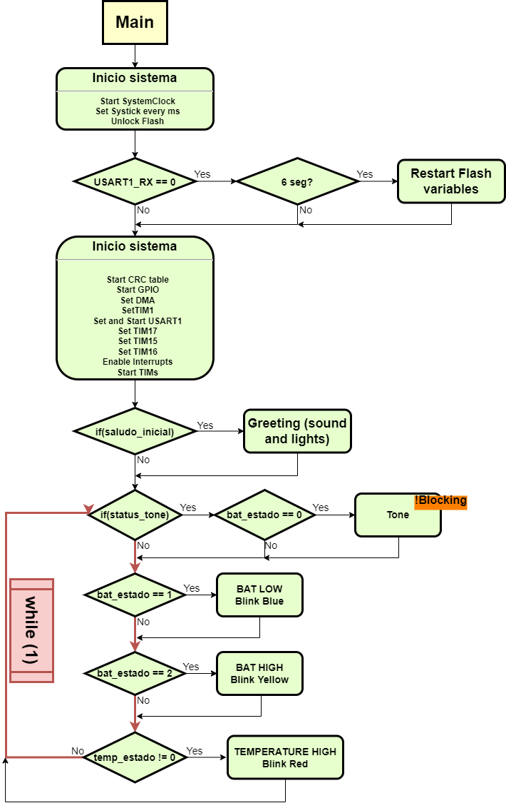
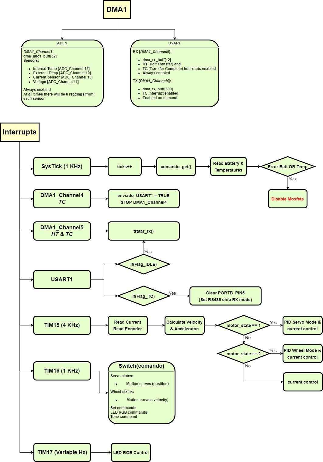
In the next few days I will upload the documentation of LibreServo commands, but in case anyone wants to read the code itself, I have made two small diagrams to help understand how LibreServo works.
![]()
![]()
-
Last steps for first official release
06/04/2022 at 21:13 • 0 commentsAlthough I had many parts of the code already done, the truth is that putting all the code together and making all the functions and internal structure non-blocking has been a much more laborious task than expected. In addition, I have programmed dozens of commands and the first version of the LibreServo Software is much more complete than I had originally anticipated.
In the following posts I will detail a little more the functions and operation of LibreServo, for now I leave a curious little video I made with the LibreServo test board v2 a few weeks ago as a small preview testing the sound function of LibreServo. Yes, LibreServo is able to generate sound making use of the DC motor.
LibreServo allows you to send blocks of commands making it much easier to send dozens of commands at once. LibreServo takes care of storing them and executing them one after another. This simple test was not really about generating music, but about seeing that the whole internal LibreServo system worked.
The commands used are as follows.
/*****IMPERIAL MARCH*****/
S1L255:0:0|S1T1567:300:100|S1T1567:10:0|S1T1567:300:100|S1T1567:10:0|S1T1567:300:100|S1T1567:10:0|S1L0:255:0|S1T1244:300:100|S1T1244:10:0|S1T1864:60:100|S1T1864:10:0|S1L0:0:255|S1T1567:300:100|S1T1567:10:0|S1T1244:300:100|S1T1244:10:0|S1T1864:60:100|S1T1864:10:0|S1L0:255:255|S1T1567:400:100|S1T1567:20:0|S1L255:255:0|S1T2349:300:100|S1T2349:10:0|S1T2349:300:100|S1T2349:10:0|S1T2349:300:100|S1T2349:10:0|S1L255:0:255|S1T2489:300:100|S1T2489:10:0|S1T1864:60:100|S1T1864:10:0|S1L0:255:0|S1T1480:300:100|S1T1480:10:0|S1L0:255:255|S1T1244:300:100|S1T1244:10:0|S1T1864:60:100|S1T1864:10:0|S1L255:255:255|S1T1568:500:100|S1T1568:10:0|S1LR;

/******MAIN THEME******/
S1T1174:75:70|S1T1174:10:0|S1T1174:75:70|S1T1174:10:0|S1T1174:75:70|S1T1174:10:0|S1T1568:450:100|S1T1568:10:0|S1T2349:450:100|S1T2349:10:0|S1T2093:75:70|S1T2093:10:0|S1T1975:75:70|S1T1975:10:0|S1T1760:75:70|S1T1760:10:0|S1T3135:450:100|S1T3135:10:0|S1T2349:450:100|S1T2349:10:0|S1T2093:75:70|S1T2093:10:0|S1T1975:75:70|S1T1975:10:0|S1T1760:75:70|S1T1760:10:0|S1T3135:450:100|S1T3135:10:0|S1T2349:450:100|S1T2349:10:0|S1T2093:75:70|S1T2093:10:0|S1T1975:75:70|S1T1975:10:0|S1T2093:75:70|S1T2093:10:0|S1T1760:450:100|S1T1760:10:0;

/*******Still D.R.E.*******/
S1T2093:100:100|S1T2093:10:0|S1T2637:100:70|S1T2637:10:0|S1T3520:100:70|S1T3520:10:0|S1T2093:300:100|S1T2093:10:0|S1T2637:100:70|S1T2637:10:0|S1T3520:100:70|S1T3520:10:0|S1T2637:100:70|S1T2637:10:0|S1T1975:100:100|S1T2093:10:0|S1T2637:100:70|S1T2637:10:0|S1T3520:100:70|S1T3520:10:0|S1T1975:300:100|S1T2093:10:0|S1T2637:100:70|S1T2637:10:0|S1T3520:100:70|S1T3136:10:0|S1T2637:100:70|S1T2637:10:0|S1T2093:100:100|S1T2093:10:0|S1T2637:100:70|S1T2637:10:0|S1T3520:100:70|S1T3520:10:0|S1T2093:300:100|S1T2093:10:0|S1T2637:100:70|S1T2637:10:0|S1T3520:100:70|S1T3520:10:0|S1T2637:100:70|S1T2637:10:0|S1T1975:100:100|S1T2093:10:0|S1T2637:100:70|S1T2637:10:0|S1T3520:100:70|S1T3520:10:0|S1T1975:300:100|S1T2093:10:0|S1T2637:100:70|S1T2637:10:0|S1T3520:100:70|S1T3136:10:0|S1T2637:100:70|S1T2637:10:0;

S1T2093:25:100|S1T2637:25:70|S1T3520:50:70|S1T3520:5:0|S1T2093:25:100|S1T2637:25:70|S1T3520:50:70|S1T3520:5:0|S1T2093:25:100|S1T2637:25:70|S1T3520:50:70|S1T3520:5:0|S1T2093:25:100|S1T2637:25:70|S1T3520:50:70|S1T3520:5:0|S1T2093:25:100|S1T2637:25:70|S1T3520:50:70|S1T3520:5:0|S1T2093:25:100|S1T2637:25:70|S1T3520:50:70|S1T3520:5:0|S1T2093:25:100|S1T2637:25:70|S1T3520:50:70|S1T3520:5:0|S1T2093:25:100|S1T2637:25:70|S1T3520:50:70|S1T3520:5:0|S1T1975:25:100|S1T2637:25:70|S1T3520:50:70|S1T3520:5:0|S1T1975:25:100|S1T2637:25:70|S1T3520:50:70|S1T3520:5:0|S1T1975:25:100|S1T2637:25:70|S1T3520:50:70|S1T3520:5:0|S1T1975:25:100|S1T2637:25:70|S1T3136:50:70|S1T3136:5:0|S1T1975:25:100|S1T2637:25:70|S1T3136:50:70|S1T3136:5:0|S1T1975:25:100|S1T2637:25:70|S1T3136:50:70|S1T3136:5:0|S1T1975:25:100|S1T2637:25:70|S1T3136:50:70|S1T3136:5:0|S1T1975:25:100|S1T2637:25:70|S1T3136:50:70|S1T3136:5:0;

S1T2093:25:100|S1T2637:25:70|S1T3520:50:70|S1T3520:5:0|S1T2093:25:100|S1T2637:25:70|S1T3520:50:70|S1T3520:5:0|S1T2093:25:100|S1T2637:25:70|S1T3520:50:70|S1T3520:5:0|S1T2093:25:100|S1T2637:25:70|S1T3520:50:70|S1T3520:5:0|S1T2093:25:100|S1T2637:25:70|S1T3520:50:70|S1T3520:5:0|S1T2093:25:100|S1T2637:25:70|S1T3520:50:70|S1T3520:5:0|S1T2093:25:100|S1T2637:25:70|S1T3520:50:70|S1T3520:5:0|S1T2093:25:100|S1T2637:25:70|S1T3520:50:70|S1T3520:5:0|S1T1975:25:100|S1T2637:25:70|S1T3520:50:70|S1T3520:5:0|S1T1975:25:100|S1T2637:25:70|S1T3520:50:70|S1T3520:5:0|S1T1975:25:100|S1T2637:25:70|S1T3520:50:70|S1T3520:5:0|S1T1975:25:100|S1T2637:25:70|S1T3136:50:70|S1T3136:200:0|S1T1975:25:100|S1T2637:25:70|S1T3136:50:70|S1T3136:5:0;
LibreServo
LibreServo is a project with the goal of easily converting any standard size servo into the smartest servo possible.


 Frequency of musical notes