Erin RobotZwrrl
-
Run modes uA/MHz
12/13/2021 at 15:43 • 0 commentsWOW! This was SUPER FUN - Micro Madness! A showdown between demo boards using Cortex-M microcontrollers. Criteria was randomly generated and both technical and fun - so any board had a fair shot. What a great moment to share with an entire group!
The board I chose was STM32L496AG Discovery, the ARM® Cortex®-M4 core-based STM32L496xx microcontroller.
The final question posed was the lowest power per MHz, running fast. From the datasheet, the answer was surprising as it had two results — both of which are impressively low power: 91 uA/MHz run mode (LDO mode) and 37 uA/MHz run mode (at 3.3V SMPS mode).
This left me curious about what the differences were, and seeing if the result represents real-world operation.
The top 3 learnings were:
- There’s a 3 uA/MHz difference when using the same settings, but with only 0.05 V difference to VDD12. Wow!
- There is a multi speed internal RC oscillator (MSI RC) that can generate 12 frequencies ranging from 100 kHz - 48 MHz. This would be really interesting to learn how it is configured, and see the results on a spectrum analyzer.
- There are a variety of run modes, each with their own configuration, that can be chosen from. It will be fun to experiment with these!
Here’s the learning journey:
-
W25Q80DV Simulator - Exercise 3b
12/10/2021 at 03:56 • 5 commentsBreaking problems down into smaller bits really helps to make a solution. The process doesn’t have to be linear like what you see below. Often working on one sub-problem helps to give a better conceptual understanding of the whole, so jumping back and forth between sub-problems is natural (despite it not seeming that way).
Exercise 3b: Make a flash simulator
To figure out where to start, list out the super basic elements. There’s gonna be an array, and the minimum functionality is to read, write, and erase.
Here’s the steps of breaking the problem down into sub-problems, and the sub-problems into further smaller sub-sub-problems. Below this list are my notes. Coding was only done at the very end. The majority of time was figuring out the problem, reading the documentation, and of course - learning!
Breakdown
Step 0: Getting background information
- Downloading the datasheet
- Understanding the block diagram
- Figuring out the nesting… flash, block, sector, page
Step 1: Determining the buffer
- Initializing an array
- Setting its vals and checking max values
- Pointer review
Step 2: Determine the address
- Do not follow this! It is actually not needed, I went down a complete rabbit hole of confusion with this
Step 3: Code the buffer
- Get the coding down right for passing it to functions, reading, writing
- Make a sample test to understand
Step 4: Make erase function
- Review documentation
- Pseudo code
- Find Instruction commands
- Also make the init function (unrelated to erase)
Step 5: Make read function
- Review documentation
- Pseudo code
- Find Instruction commands
Step 6: Make write function
- Review documentation
- Pseudo code
- Find Instruction commands
Step 7: Make test flow
- Based on the test description in the book Making Embedded Systems by Elecia White
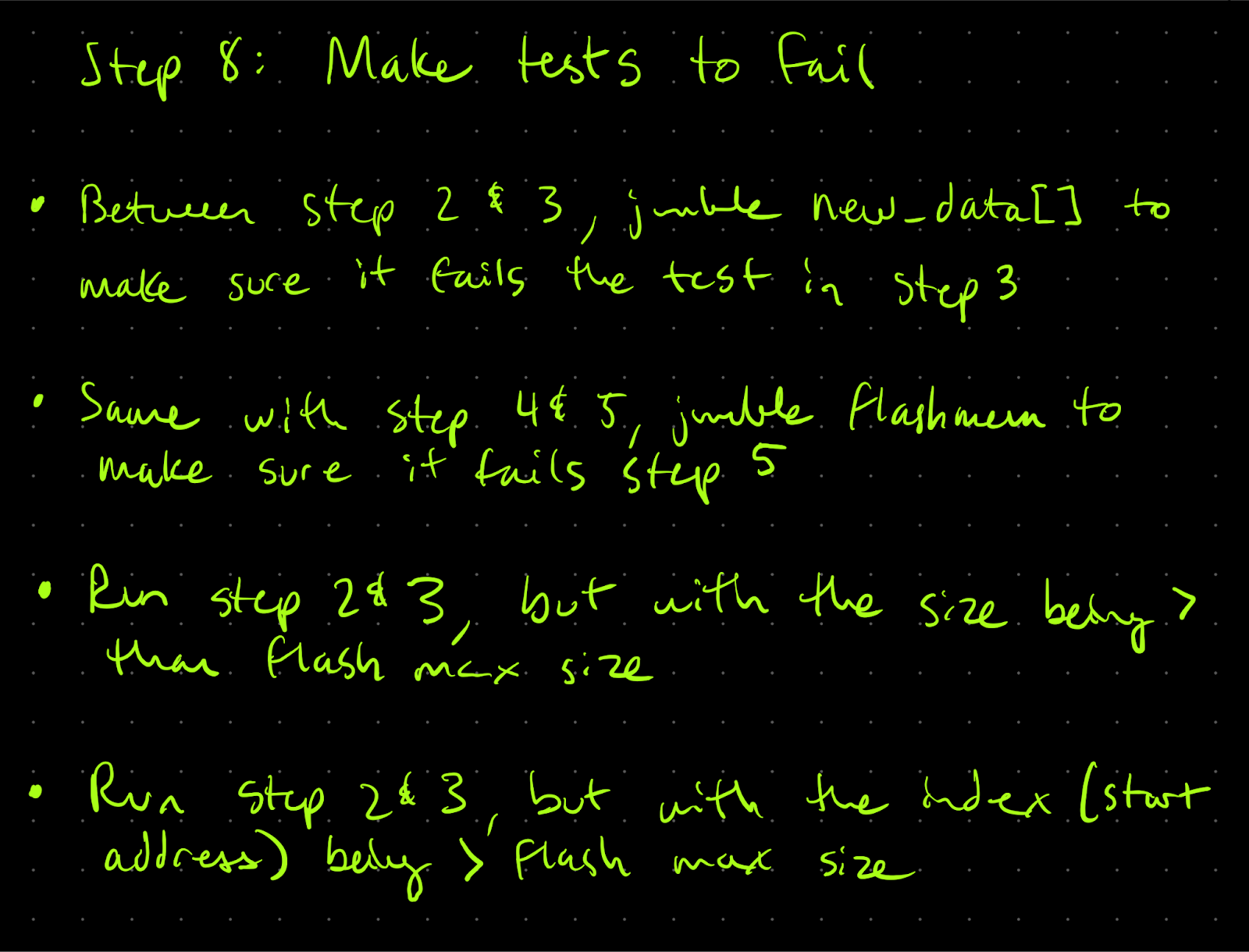
Step 8: Make tests to fail
- Brainstorm edge cases and ways it would not work
Step 9: Code it
- Code it, compile it, test it - one new thing at a time
Notebook
Step 0
Step 1
Step 2 (Do not follow!!)
Step 3
Step 4
Step 5
Step 6
Step 7
Step 8
Step 9
Code
Time
10.75 hours figuring out & learning
3 hours coding
1 hour documenting -
Stuck on Error_Handler (Resolved)
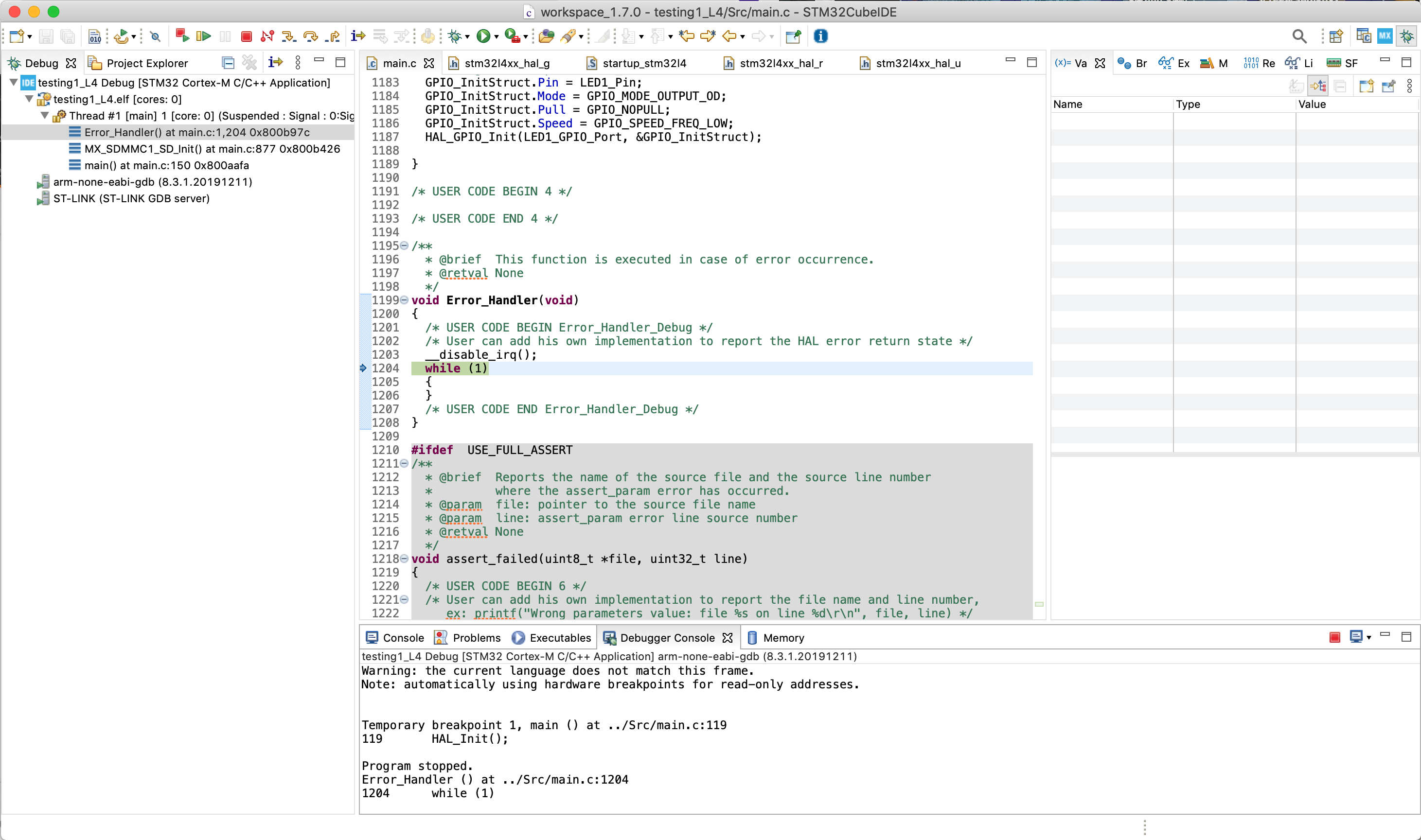
11/27/2021 at 02:06 • 0 commentsSolution: In the debugger view I must have missed that on the left hand side you can see the function that calls the error handler. This narrowed it down to the SD card initialization. Commenting out MX_SDMMC1_SD_Init in main "fixed" it, but this would need a proper solution later if using the SD card. As well, if using CubeMX to regenerate the code, will need to remember to comment it out again.
Made blink work once, now unable to get anything to run on the STM32L496. Using debug mode and pausing the program, it is stuck in Error_Handler. The code in main loop is commented out, and everything is as it was using the STM32CubeMX to set up the board using their template.
![]()
In STM32CubeProgrammer, tried a mass erase. There was no change.
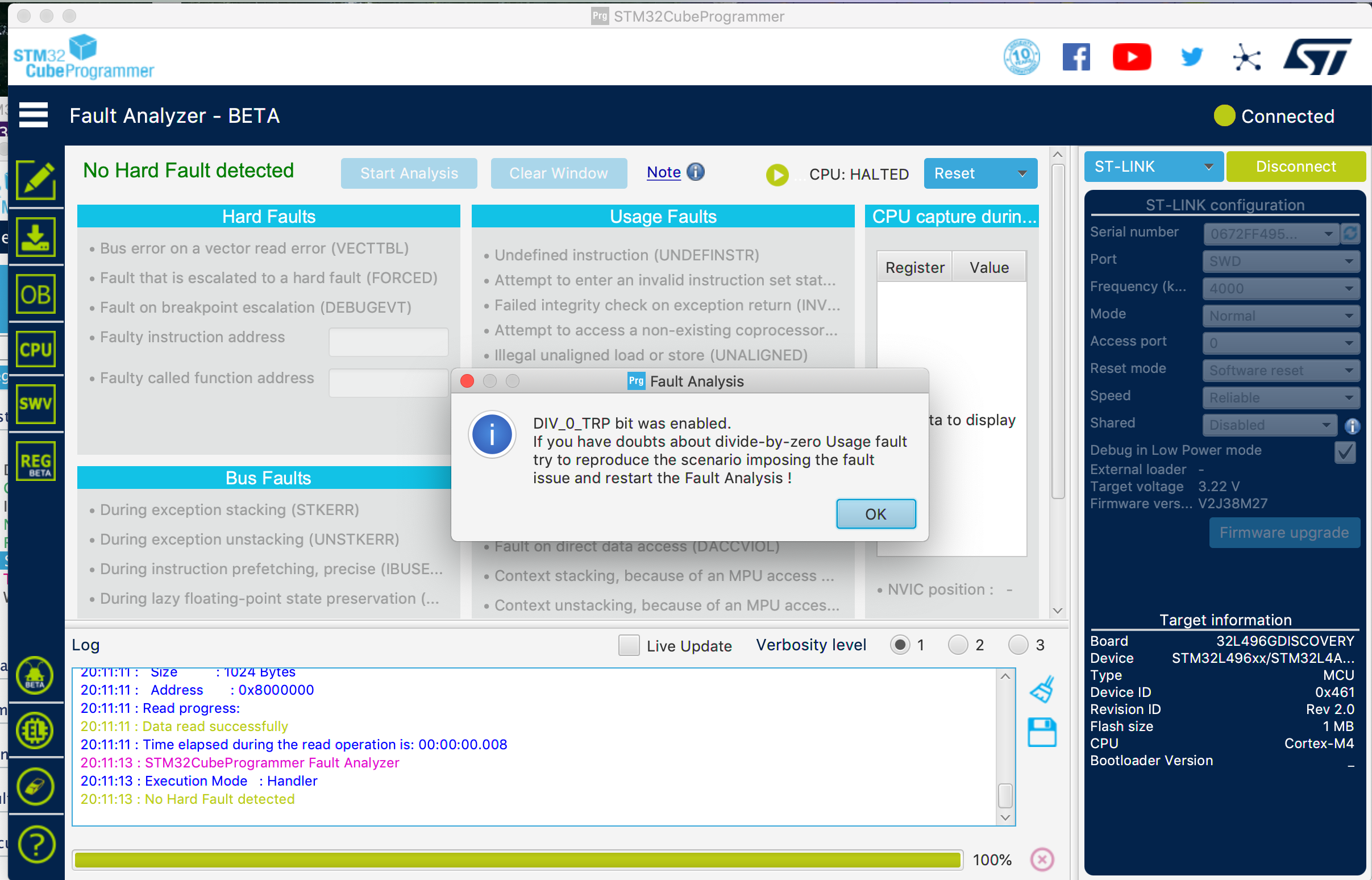
In fault analysis, it says DIV_0_TRP was enabled. When running fault analysis again, the same error had disappeared.
![]()
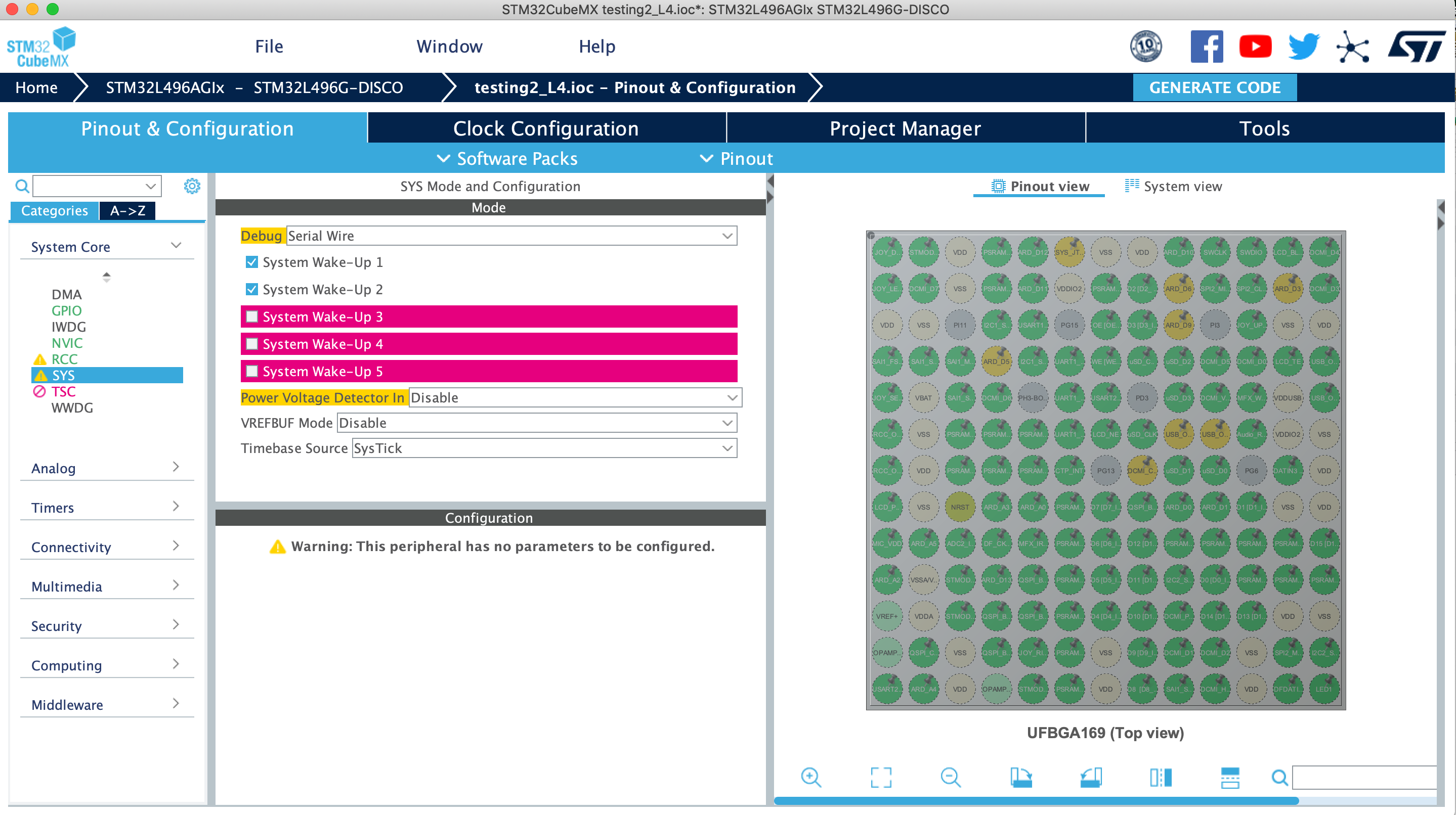
Unsure the source of the error. Perhaps something with STM32CubeMX?
![]()
Further debugging is needed
-
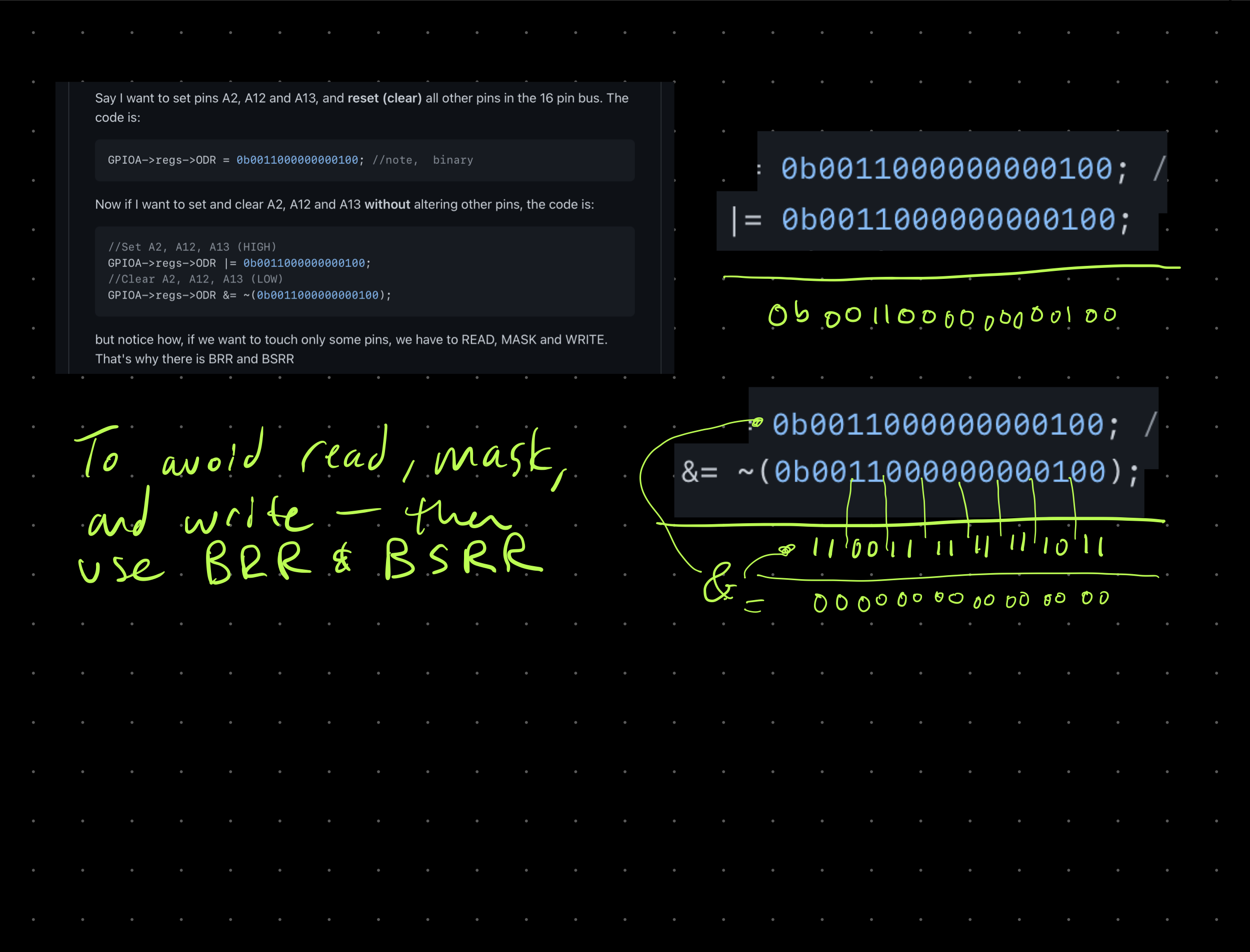
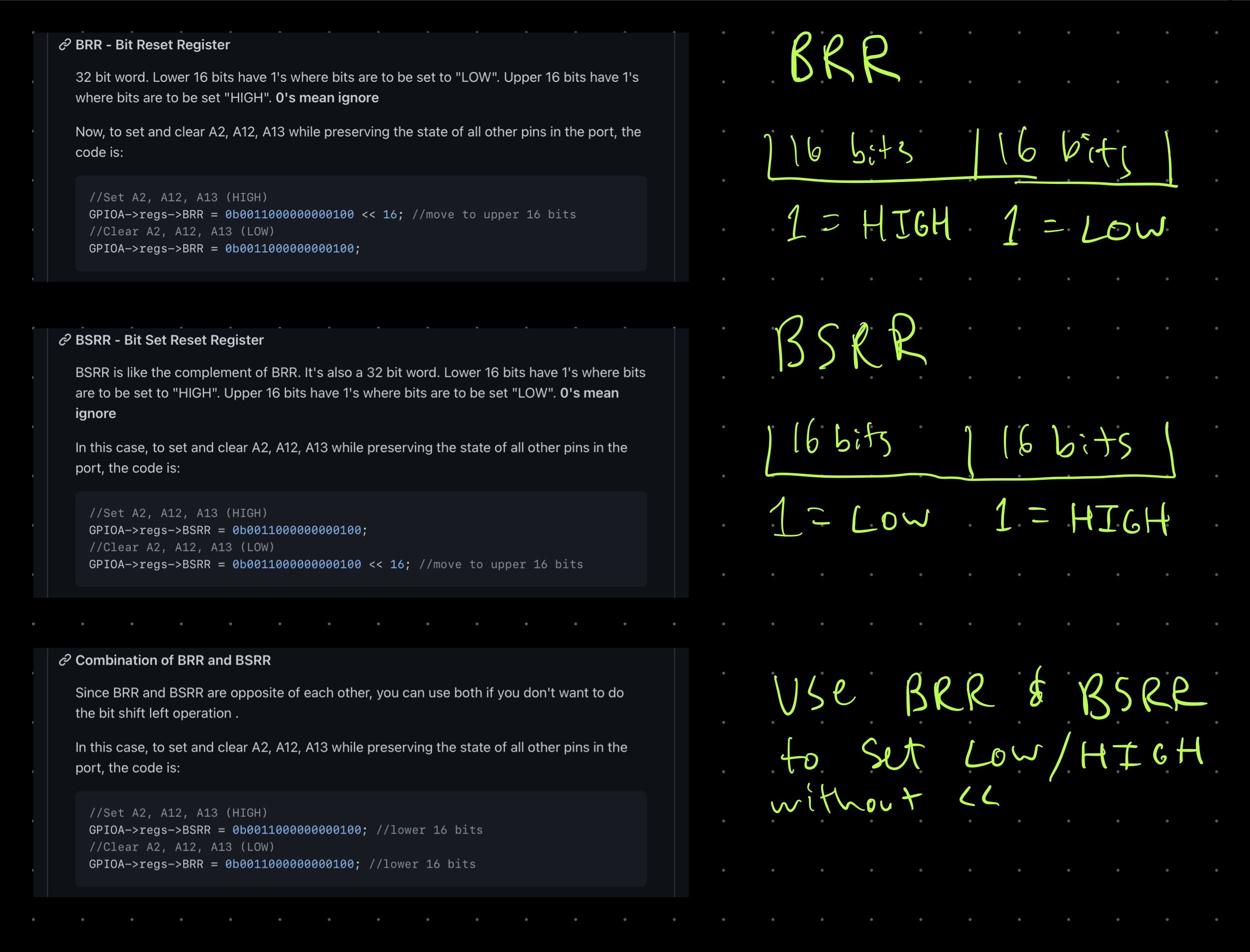
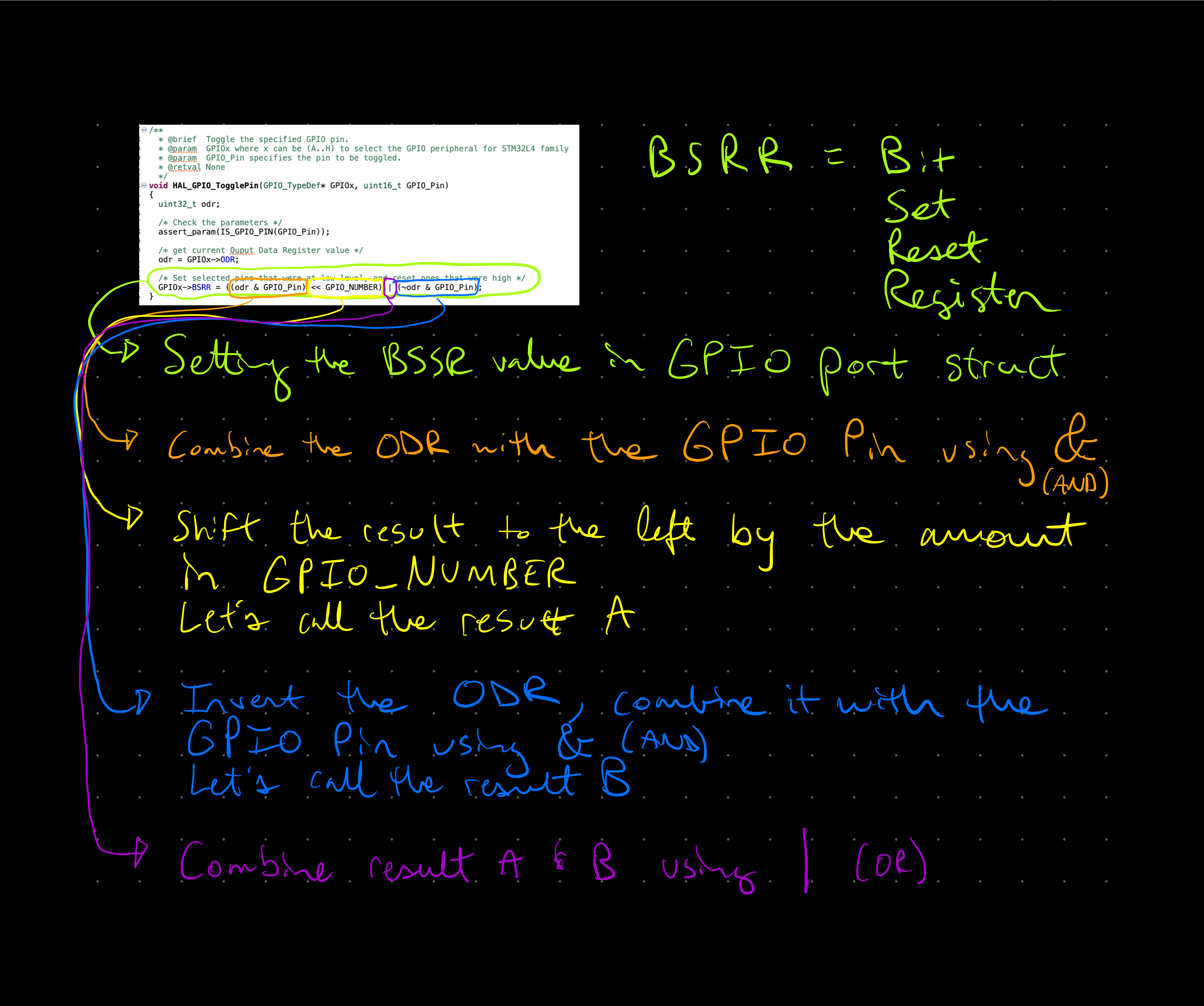
BSRR is cooler than ODR
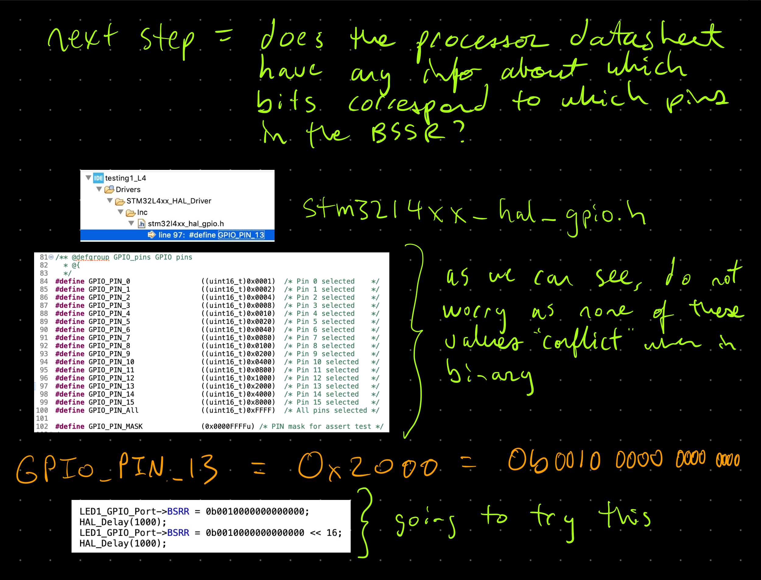
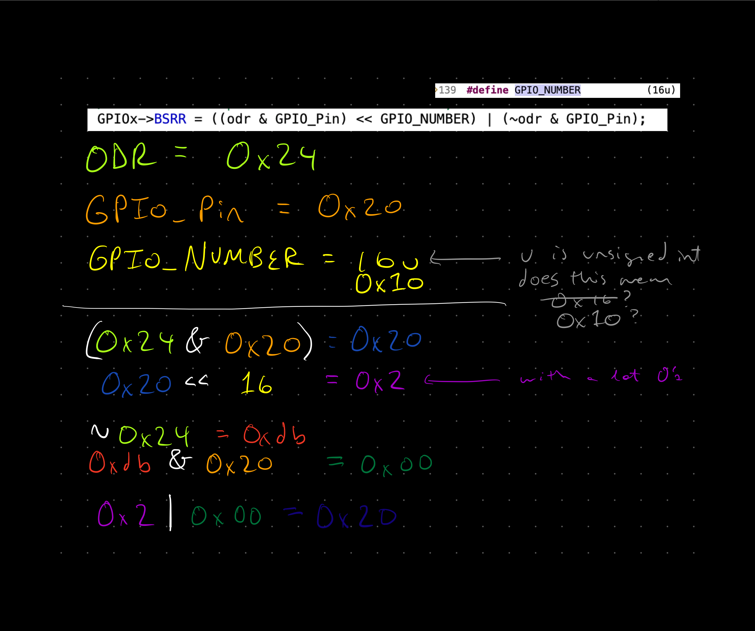
11/26/2021 at 04:31 • 0 commentsThe outputs can be toggled by shifting the bits on the BSSR register. The bits correspond to the GPIO pin addresses.
Check out the STM32duino GPIO Registers and programming gist note
Here are my notes
![]()
![]()
![]()
0b0010 0000 0000 0000 is GPIO_PIN_13 in binary. Setting the BSSR to this means it should first be high, then after the bitshift of 16 bits to the left, then it will be low (if understanding it correctly).
The reason for using BSSR is to avoid any problems that might occur in this multi-step process with ODR needing to read, modify, and then write. BSSR can be done in one step. Check out the box 'Writing an Indirect Register' on page 123 in Making Embedded Systems.
-
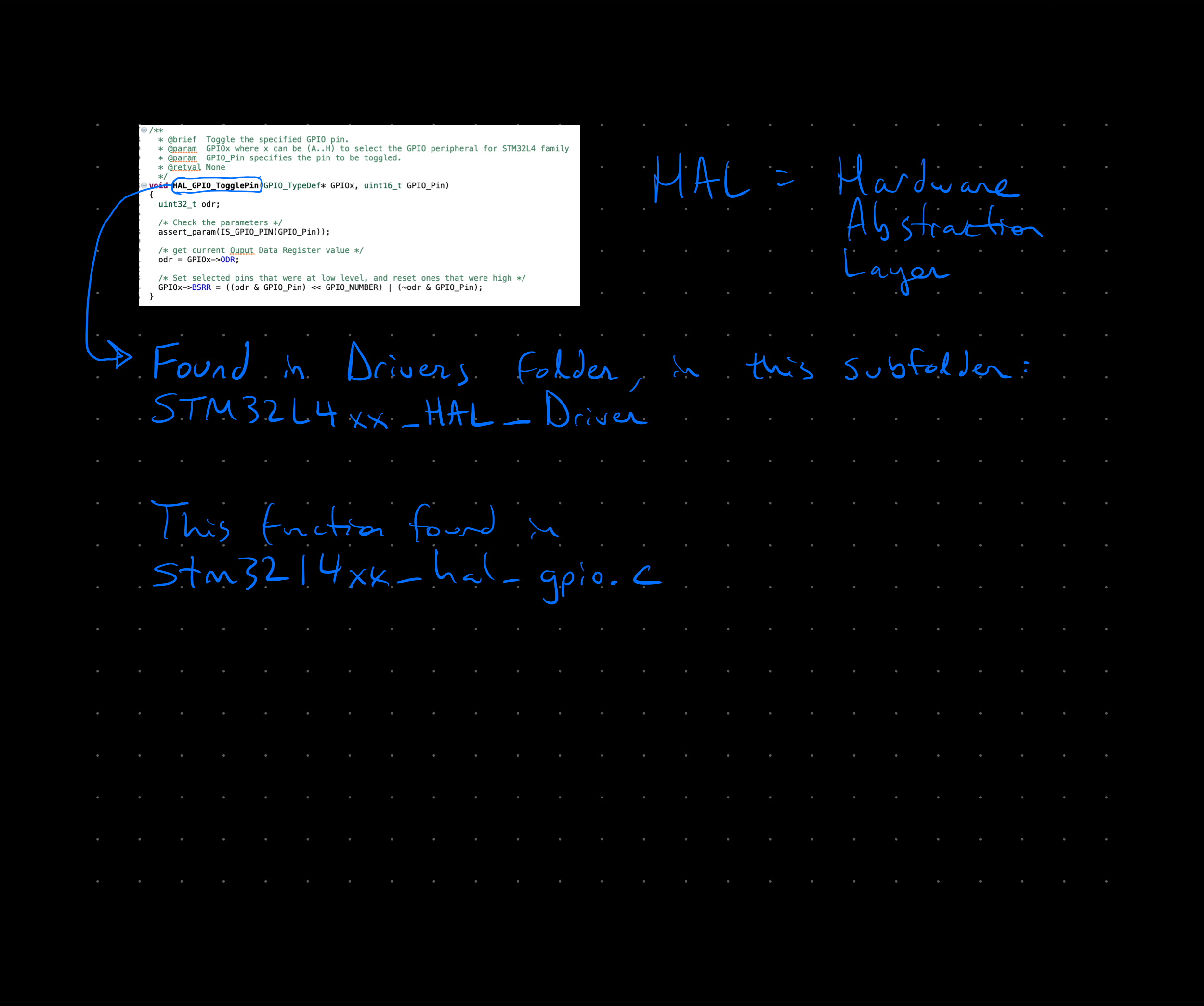
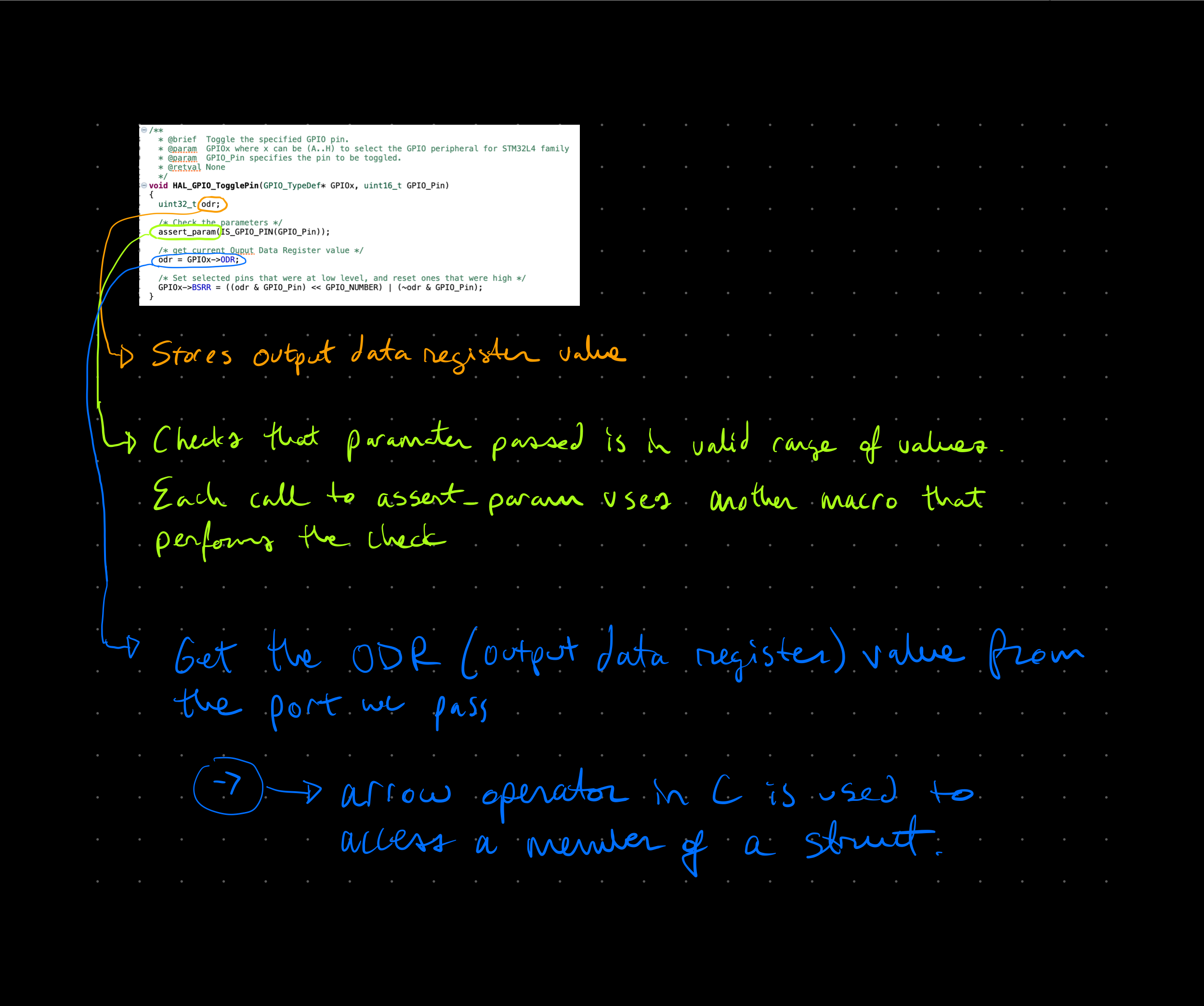
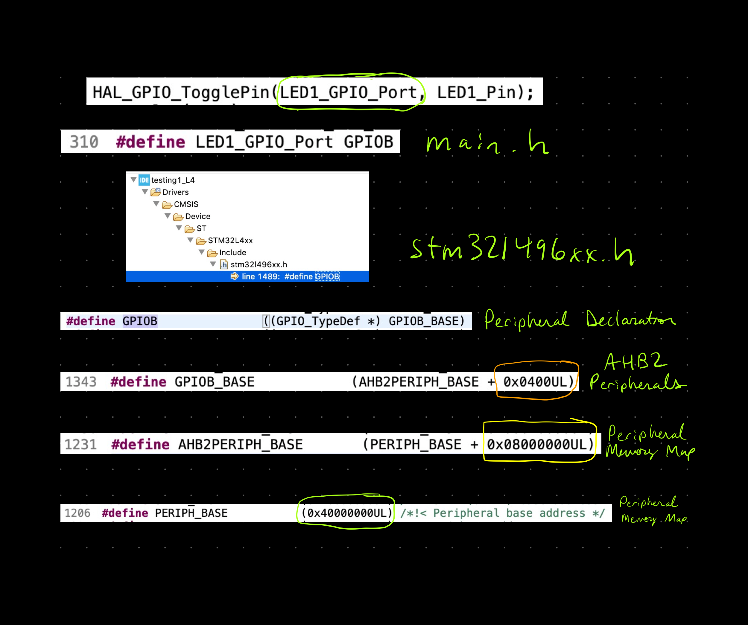
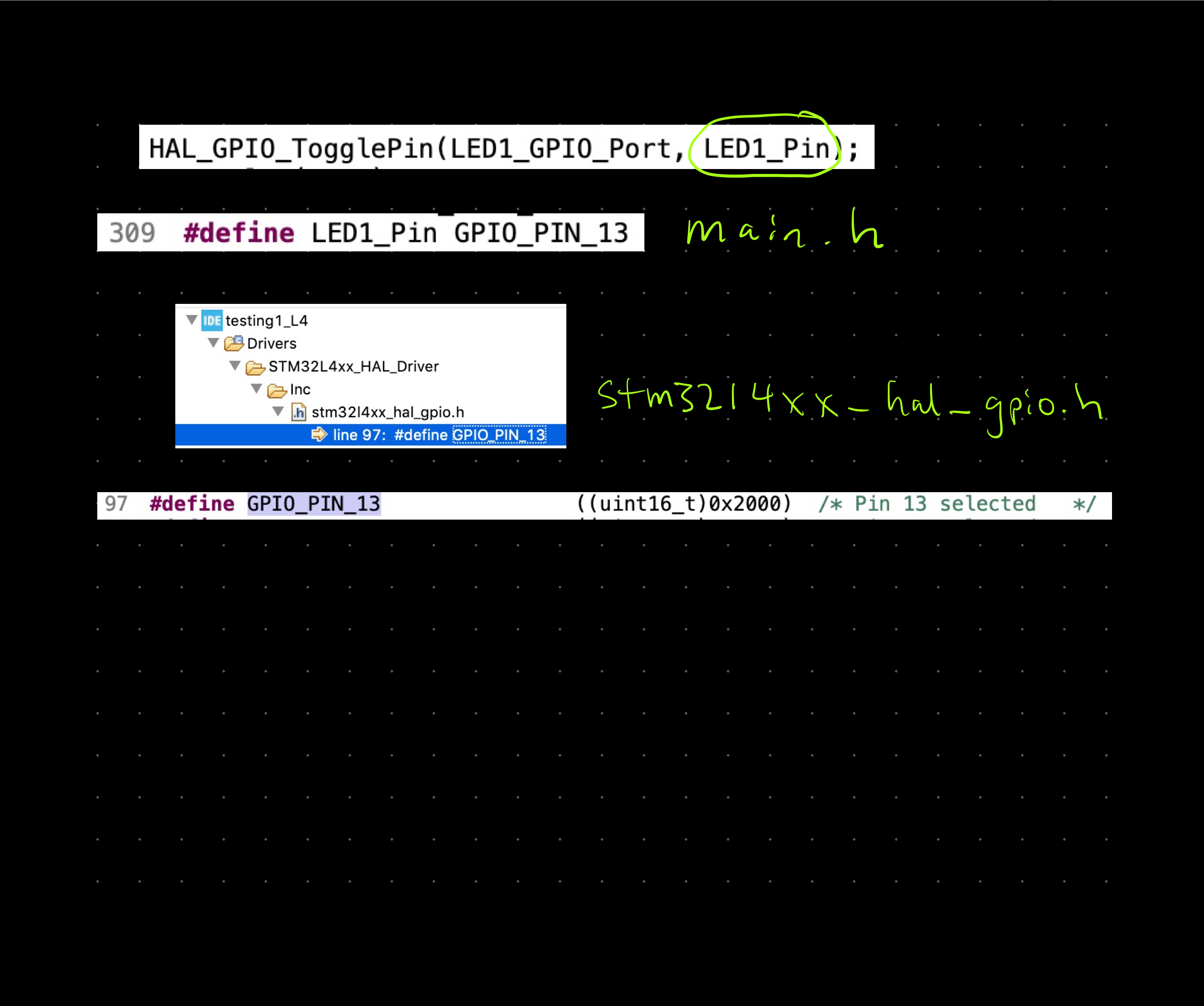
Tracking HAL_GPIO_TogglePin
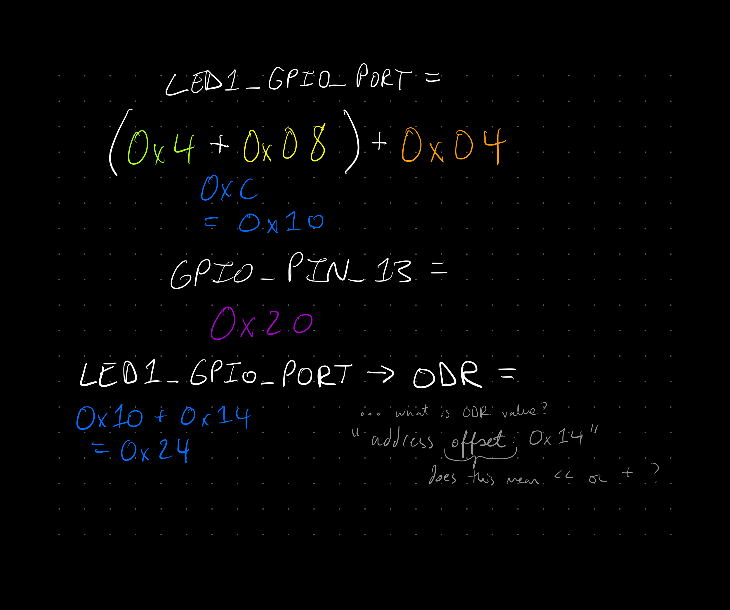
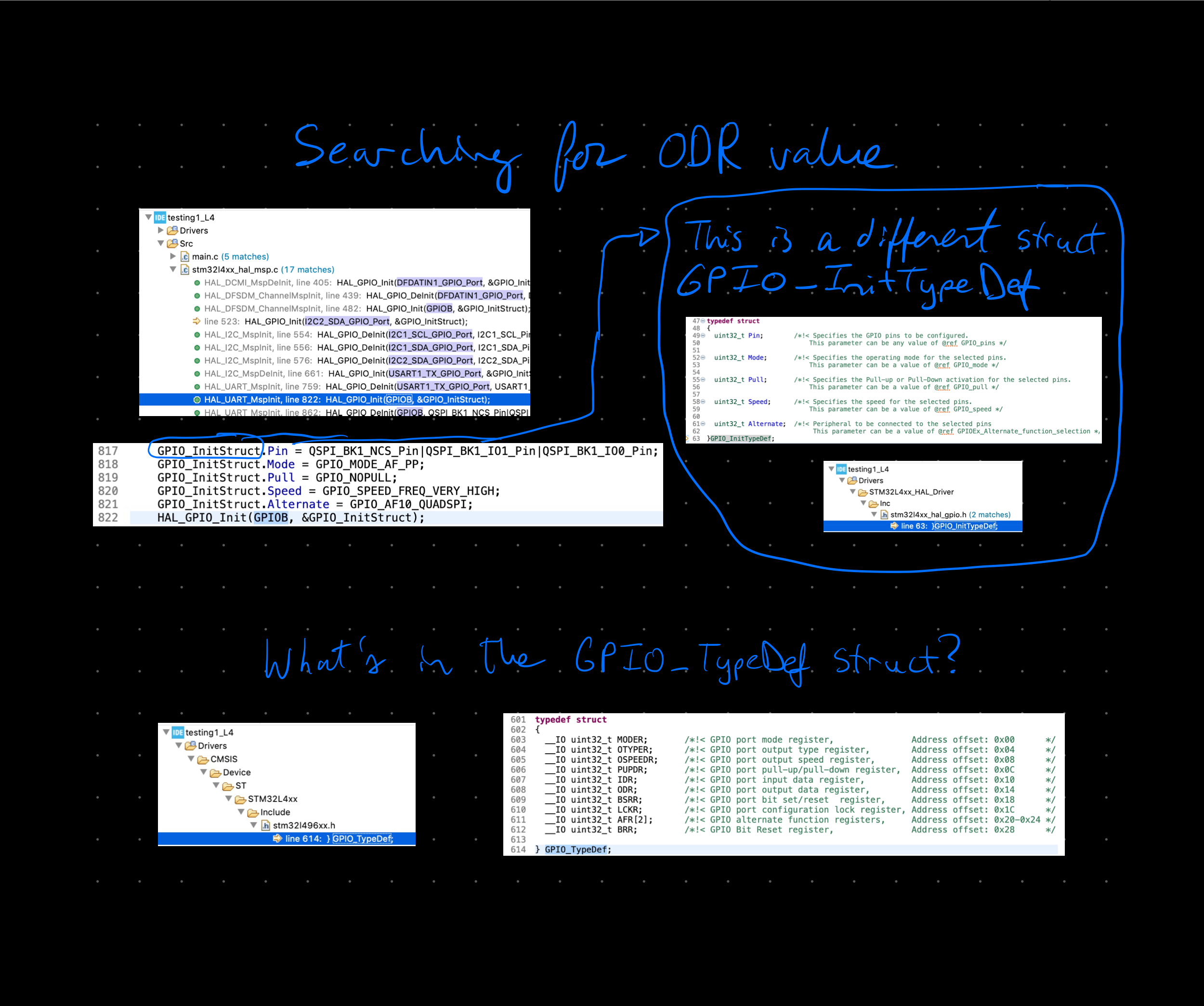
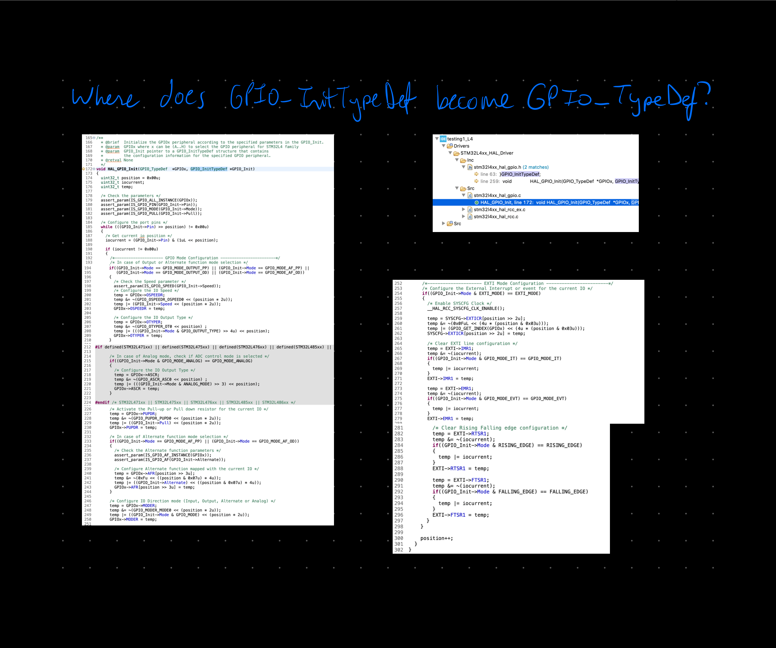
11/22/2021 at 15:13 • 0 commentsFiguring out how a LED blinks lead to tracking down variables and register addresses. There is something that is unclear - What is the Output Data Register and does this ever change? How does the LED get toggled when the values are (seemingly) the same? That doesn’t seem to make sense…
Here are my notes:![]()
![]()
![]()
![]()
![]()
![]()
![]()
![]()
![]()
The goal with this is to understand how LED toggle actually works
Stuck at this point
- What does change for toggling the LED?
- Does ODR ever change?
-
STM Disco Board
11/09/2021 at 02:49 • 0 commentsA STM32 will be used for this project. There are a few options to choose from:
This project does not need ultra low power in particular. It will need to be fast to detect the encoder, step the stepper, and do all the other things. This narrows it down to G and F. Narrowing it down further is four to choose from.
Board Comments STM32F072B-DISCO Linear touch sensor will be useful for controlling speed Nice single row layout for the broken out pins F0 = 48 MHz STM32F411E-DISCO IMU would be useful for learning and other experiments — can always use a potentiometer for controlling speed F4 = 180 MHz STM32F407G-DISC1 Outta stock STM32F429I-DISC1 No need for the screen
Based on this the STM32F411E-DISCO is chosen -
Encoder
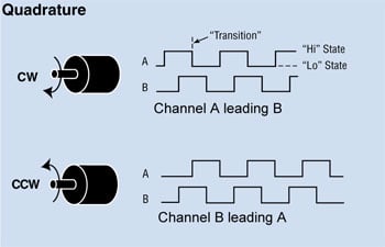
11/09/2021 at 02:27 • 0 commentsA quadrature encoder is an encoder that measures both speed and direction. It's quad (meaning 4) because there's two sensors that can give two values (1 or 0).
There are two square waveforms that are 90 degrees out of phase with each other. The direction is known depending on the order. The frequency is known depending on how many.
![quadrature encoder A-B output channel diagram]() [source] Also more information available here
[source] Also more information available hereIt is possible to increase the resolution of the encoder by detecting both the leading and trailing edges of the pulse. When done for both channels, it quadruples the resolution aka pulses per revolution.
Here are the alternative encoder methods, and the reason for choosing magnetic over them:
Encoder Method Reason for Not Choosing Optical End device would be deployed in a dusty environment where optical could be prone to errors Magnet on drive shaft Backlash in gearbox of the device makes the movement from the drive gear different than the actual on the output gear Field oriented control Design of this device should be portable to different configurations, whether that's stepper, brushed, brushless, or even no motor Downsides to the magnet approach are the cost of the magnets and the size.
Next step for encoder work is determining the hall-effect sensors, magnets, placement of magnets.
-
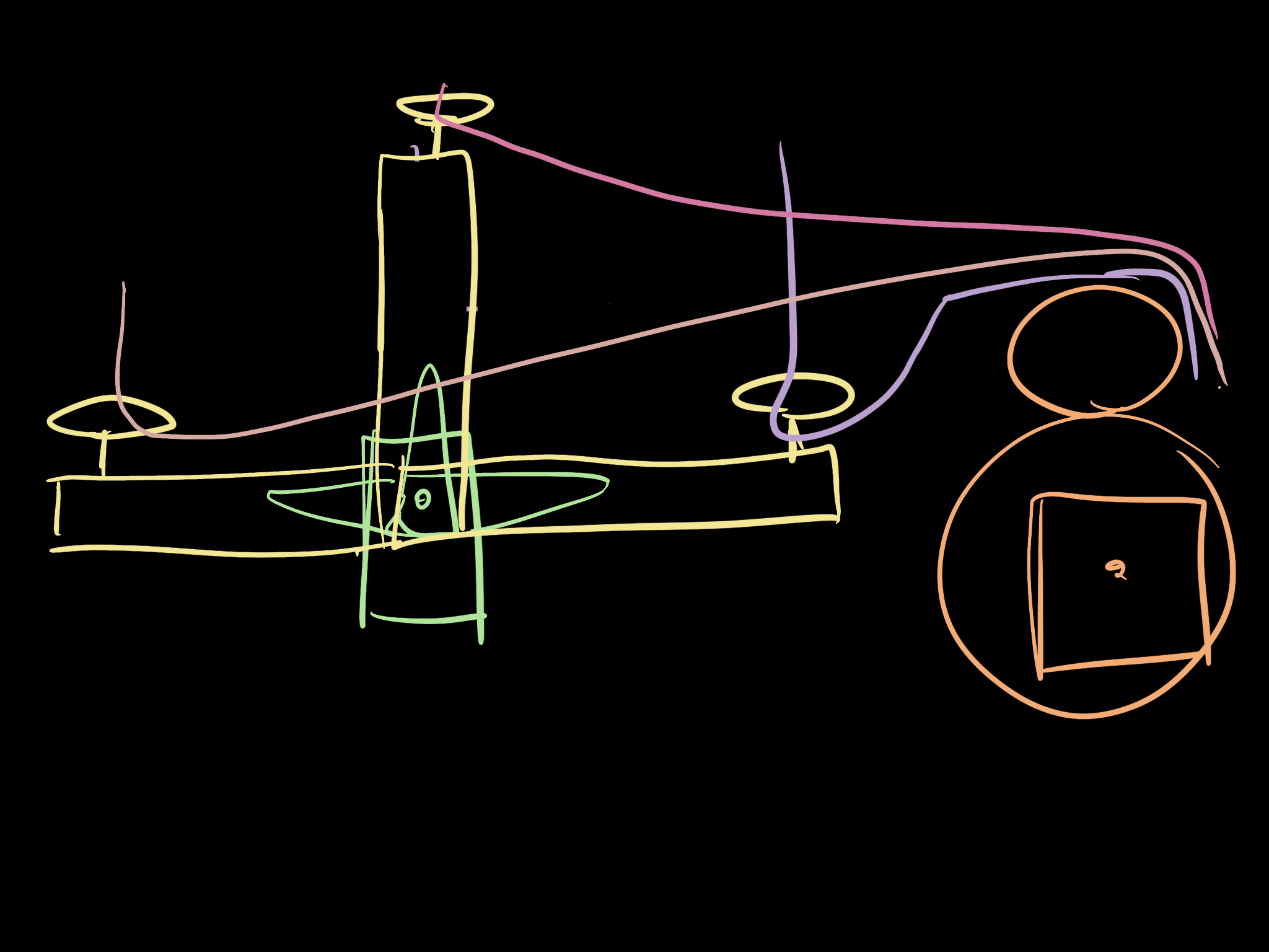
Draft Mech Concept Sketch
11/09/2021 at 02:01 • 0 commentsThis is a draft sketch to illustrate the concept:
![]()
Orange
Stepper motor and gears. On the output gear will be a spool for the rope. As well as a magnet disk with 8x magnets in a circle. A quadrature encoder (2x hall-effect sensors) will be close to the magnet disk [not pictured]. Gear ratio is larger-to-smaller as the reeling needs to be fast.
Green & Yellow
Servo arm with an extension to pivot the rope guide loop. This moves the point of rotation for the rope.
Pinks
Rope (paracord). This will be wound on a spool, mounted on the output gear.
The focus is on the embedded system, so it's possible not all of these mechanical pieces won't be built. This was to show the concept from a mechanical perspective to give a better idea of the project purpose.