 Anton
Anton-
1Preparing the AC4014
remove the filters and all the screws:
![]()
you can now easily remove the back cover.
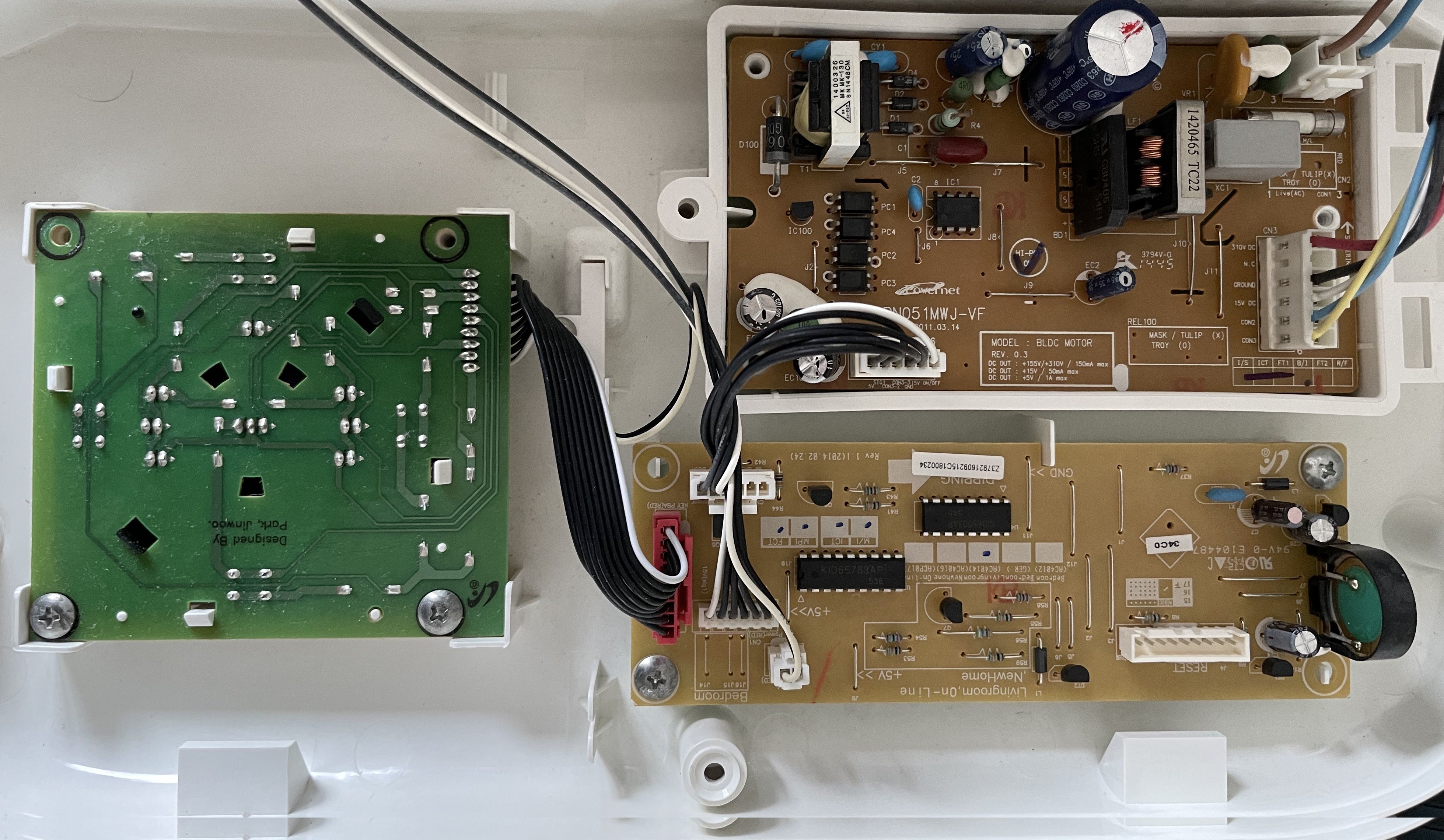
Inside you find the electronics in the top part:
![]()
-
2Building the additional electronics
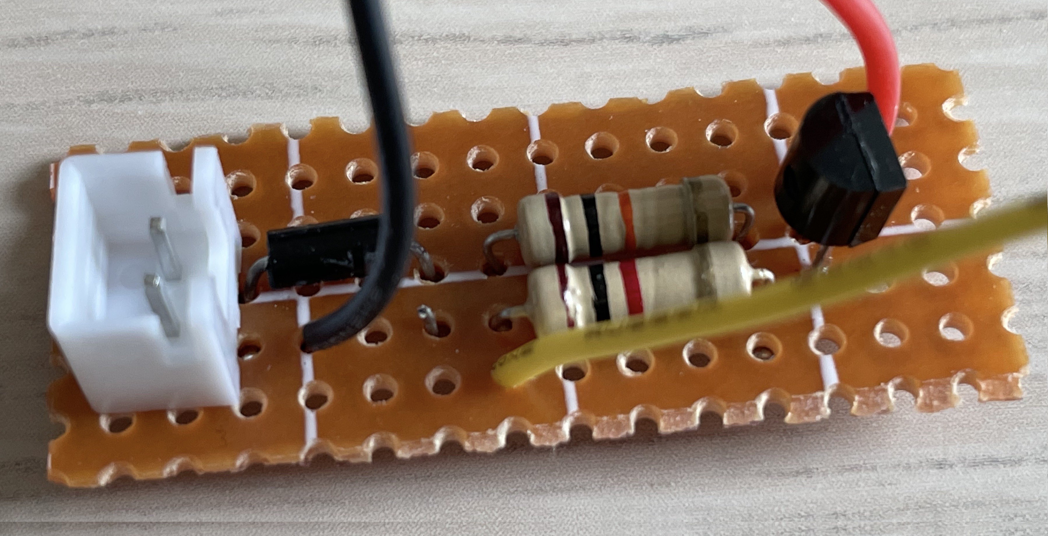
In order to have a galvanic isolated component, I decided to control the on/off and fan switches with relays and the air purifier status (on/off) with a transistor that sets a GPIO of the ESP high. I found it minimal invasive and it really works very well.
![]()
I soldered the few components for the status switch on a perf board which can be stored underneath the ESP32.
![]()
-
3Assembling the electronics
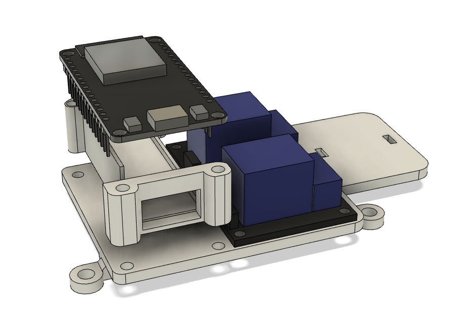
You can use the 3d printed mount bracket or you can also hot-glue the components in the air purifier cover.
![]()
The 3d printed bracket consists of 2 parts: the mount plate and the electronics box.
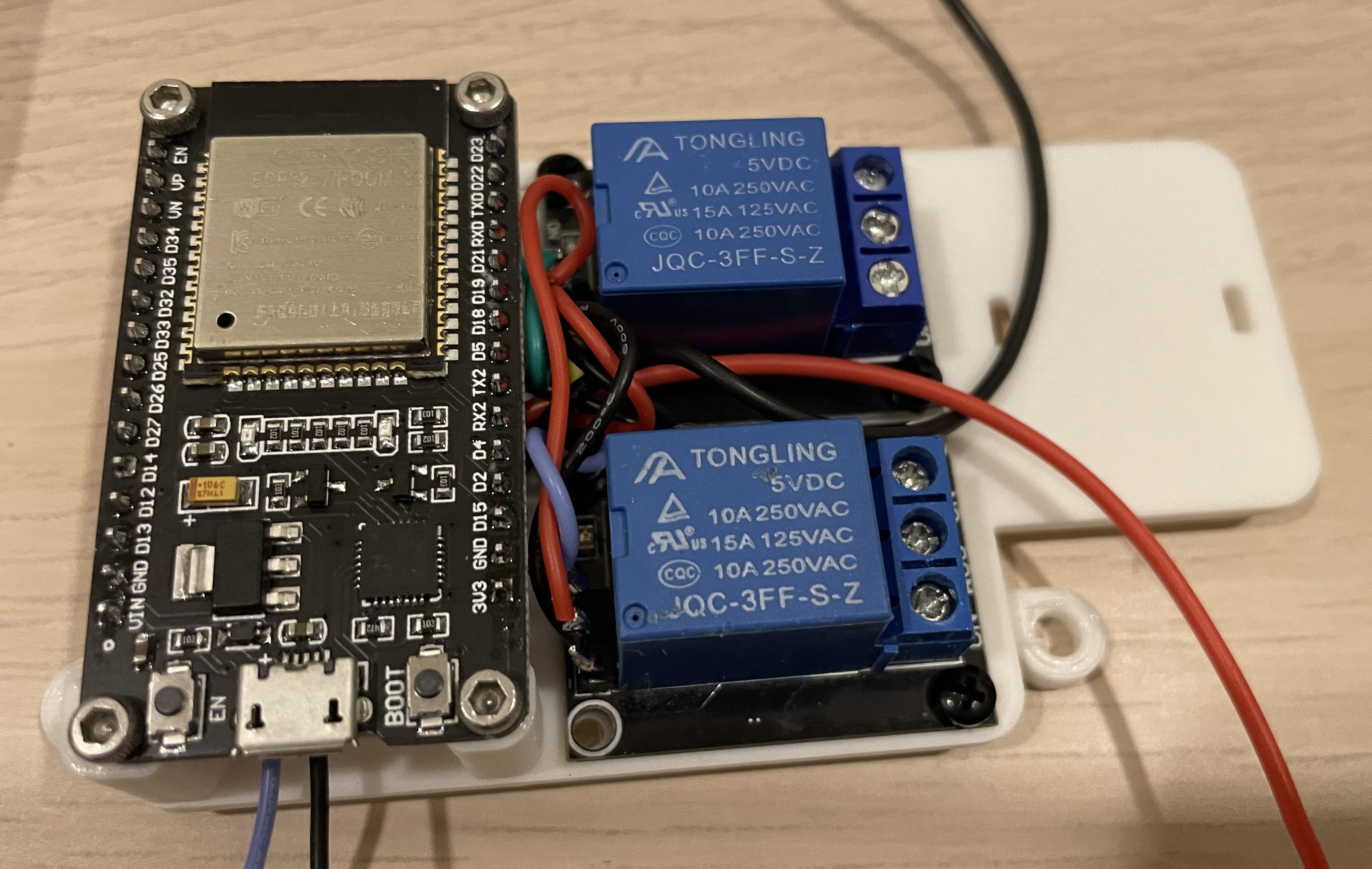
Mount the relays with 2.5mm screws and nuts, put the status electronics in the box, connect everything and put the ESP32 on top of the box. Fix it with 2.5mm screws and nuts.
![]()
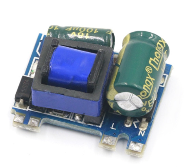
I did not use a 5V supply from the AC4014 boards, but added an AC-DC converter (5V 700mA) which I connected to the main power and mounted onto the mount plate with a zip tie. The ESP32 is powered through the 5V pin.
![]()
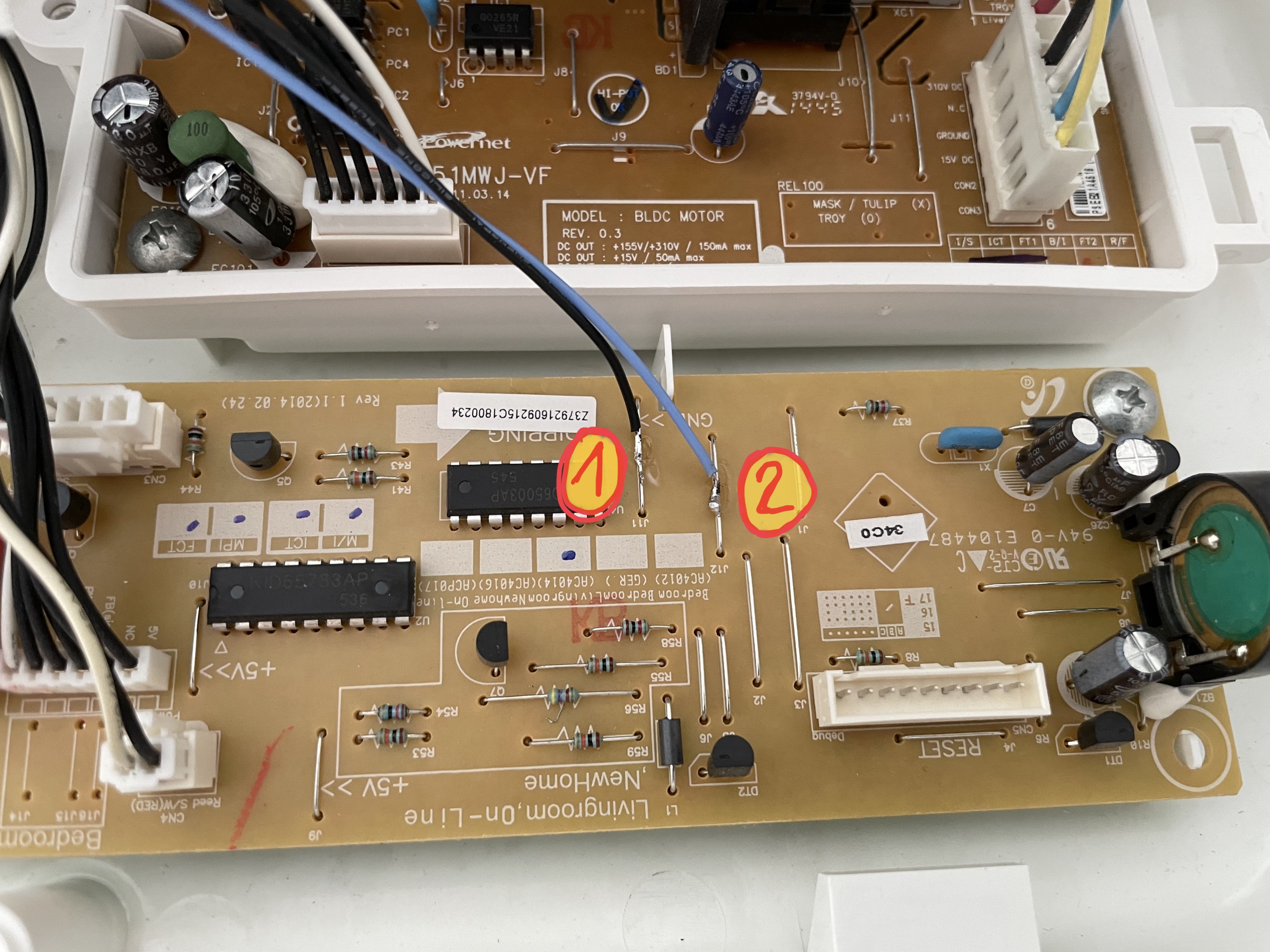
Follow the schematics and solder the connections to the AC4014 boards as indicated by the numbers:
![]()
![]()
-
4Adding the Air Purifier to ESPHome
Add the ESP32 to to your ESPHome and add following lines to the corresponding yaml:
(choose your own names and edit the GPIO numbers accordingly)
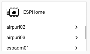
switch:
  - platform: gpio
    pin: GPIO18
    inverted: no
    id: relay
  - platform: template
    name: "Air_3_fan"
    turn_on_action:
    - switch.turn_on: relay
    - delay: 300ms
    - switch.turn_off: relay

  - platform: gpio
    pin: GPIO2
    inverted: no
    id: button
  - platform: template
    name: "Air_3_on_off"
    turn_on_action:
    - switch.turn_on: button
    - delay: 300ms
    - switch.turn_off: button

binary_sensor:
  - platform: gpio
    pin:
      number: GPIO22
      mode: INPUT
    name: "Airpurifier3"
    filters:
      - delayed_off: 200ms
Once updated the ESP32, it should be recognised in the ESPHome integration:
![]()
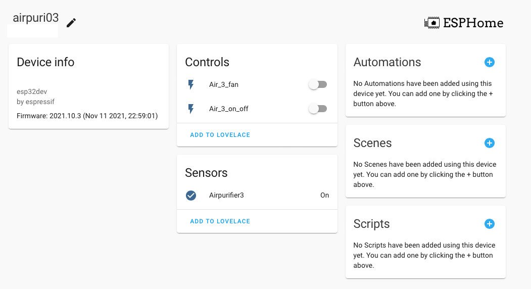
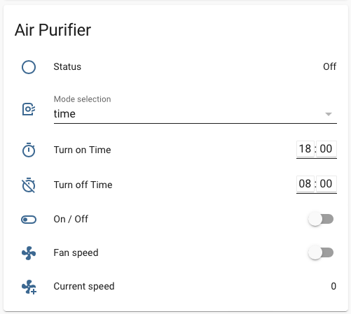
You can now find its controls and sensors, add them to lovelace and build automations with it.
![]()
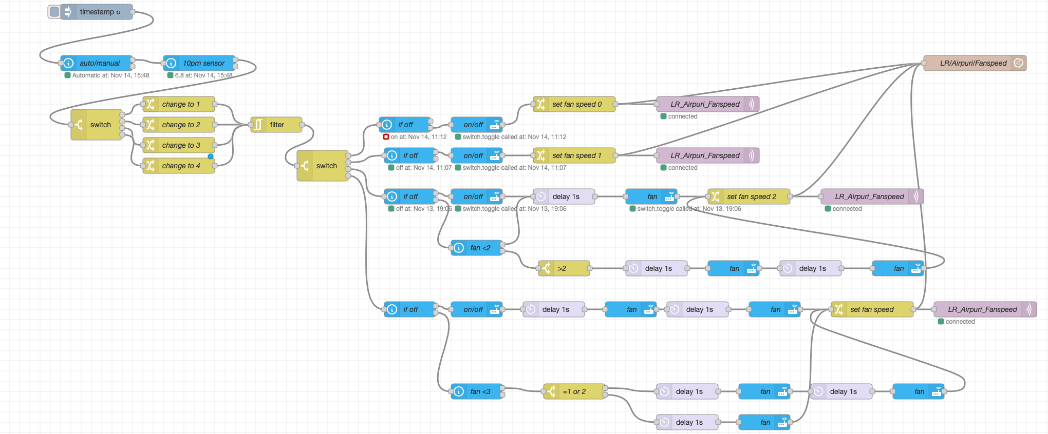
With the status sensor and the on/off and fan switch, you can write rules in node red
![]()
in this example the fan speed is calculated in node red and made available in lovelace. The different workflows for manual and automatic are set in home assistant and used in node red.
![]()
Making an old Air Purifier smart
adding the Phillips AC4014 to a Home Assistant network


Discussions
Become a Hackaday.io Member
Create an account to leave a comment. Already have an account? Log In.