 Tim
TimHere is an attempt in taking the strip concept and making it a bit smaller and easier to assmble.
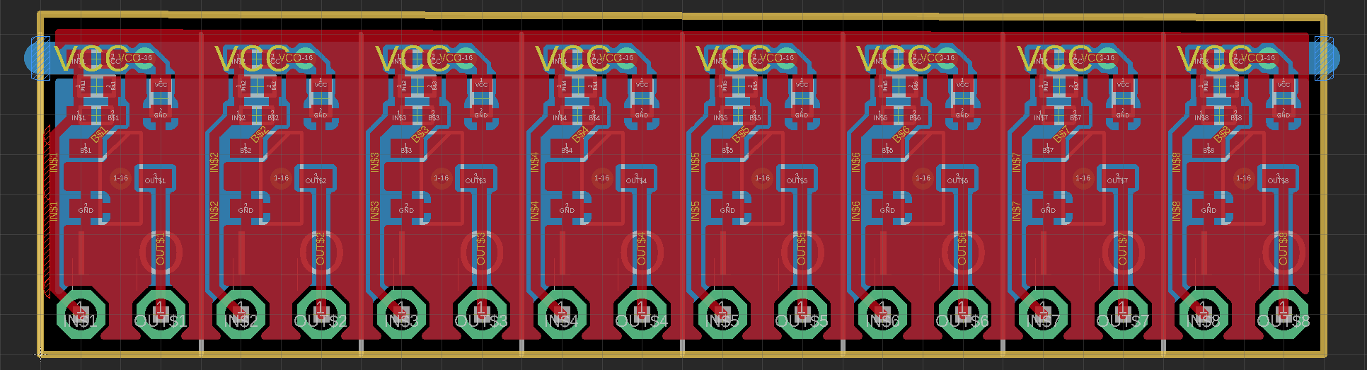
I moved all components to the top to allow automated assembly. If we use an assembly service anyways, we can switch all the passives to 0402 and save a lot of space. The VCC power rail is now routed on the rear side, while there is a large groundplane for GND on both sides of the PCB, that will also help with shielding.
This new arrangment allows reducing the strip width to 0.2". Each element is a single inverter with pull up at the input. Multiple inverters can be combined to form wide input NOR2 gates in RTL.
A base resistor bypass cap is added to improve switching speed. There is no space for a schottky clamp diode, but probably the parasitics of the wiring scheme on a breadboard will limit the achievable speed a bit anyways. Each element also has a decoupling capacitor.
Open and still unsolved: How to connect to the power lines?
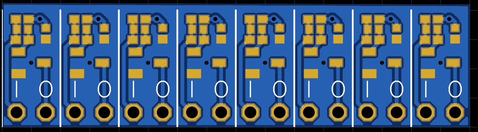
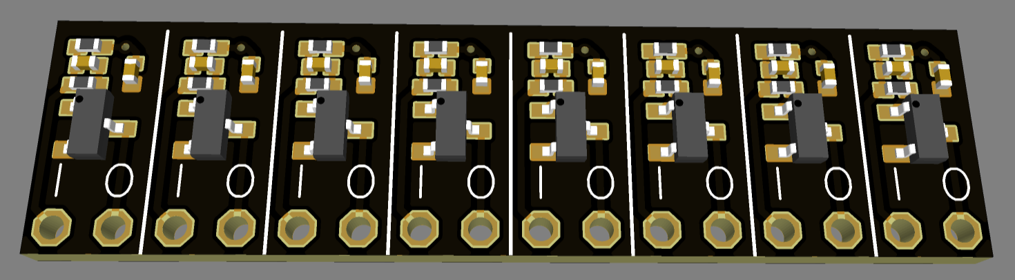
Some more renders below.
Edit: One could also fit a clamping diode in there. But then the text has to be moved to the rear side. Second from left:
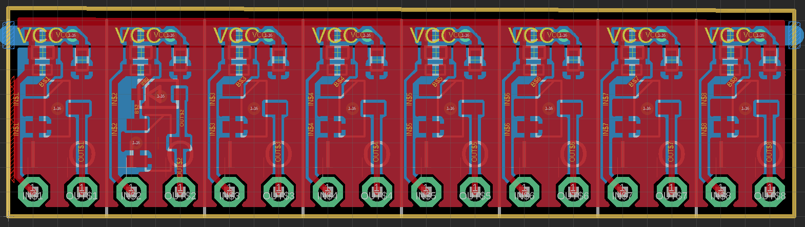 EDIT2: A version with drill-lines for easy separation
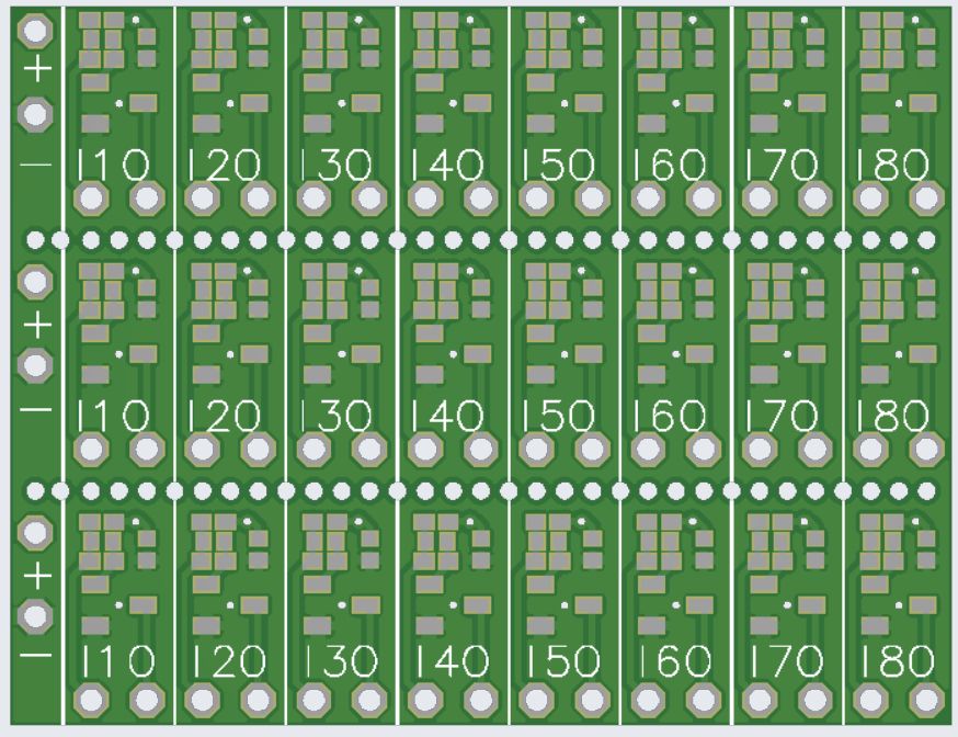
Discussions
Become a Hackaday.io Member
Create an account to leave a comment. Already have an account? Log In.
@Tim The "edit" seems to be only on one gate.
What package footprint did you use ?
Are you sure? yes | no
indeed. Just a test.
SOD-323
Are you sure? yes | no
nice :-)
Are you sure? yes | no
"How to connect to the power lines?" I contemplated this question already.
I imagined something like the "real" LED strips, which can be joined by soldering exposed pads. In our case, the pads can simply be exposed copper. A bit of resistor leg might also help.
But the corollary is : how do you break/cut the strip to a desired length ? V-groves ? microdrills ?
Are you sure? yes | no
>how do you break/cut the strip to a desired length ? V-groves ? microdrills ?
The design is probably too small for V-groves. But I made very small breakout boards before by separating them with microdrills on 0.8mm FR-4 thickness. You could simply cut them apart with scissors.
Are you sure? yes | no
I have an open order at JLCPCB and just added a few PCBs as above for testing without assembly. I can share some with you.
Are you sure? yes | no
Awesome !
Are you sure? yes | no
More strips per board could be achieved if you let go of the I and O marks, or even put them on the other side of the board :-)
Are you sure? yes | no
yeah, i though about that. Could flip the parts to the bottom. But then it is always better to be able to look at the components
Are you sure? yes | no
flip the marking to the bottom instead, it's the same, right ?
Are you sure? yes | no
"probably the parasitics of the wiring scheme on a breadboard will limit the achievable speed"
Why limit ourselves to breadboards ? ^_^
Are you sure? yes | no