-
13D print the required components
- Use a high infill (40%+) with at least three perimeters (assuming a 0.4mm nozzle)
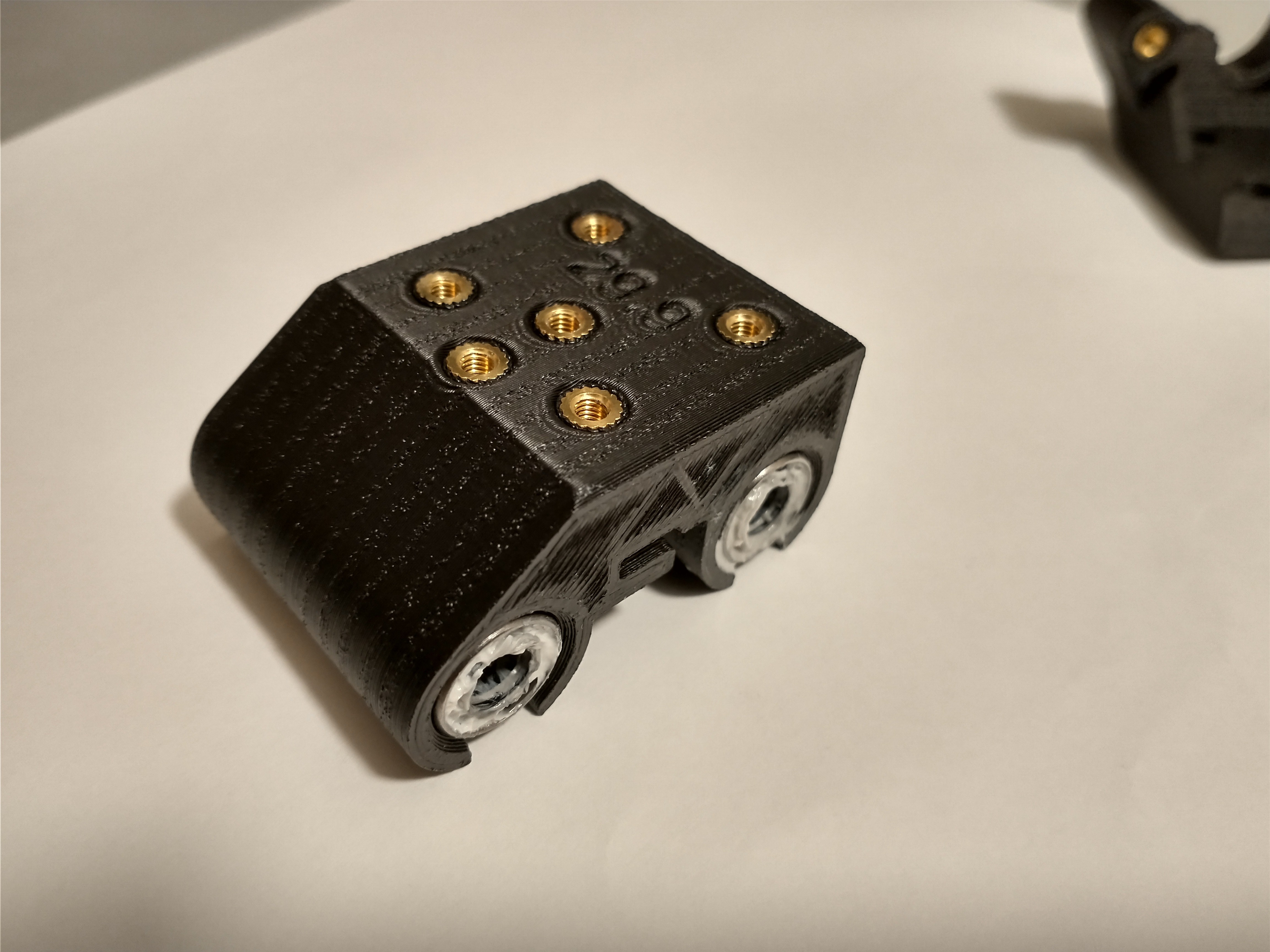
- 1x X-carriage (use a heat-resistant material)
- There are two versions - a 29.9mm spaced bearing carriage and a 30.0mm space bearing carriage. Measure the distance between the rods using a Vernier caliper to determine the correct part for your printer. The 29.9mm (labeled in the images) was used in this project
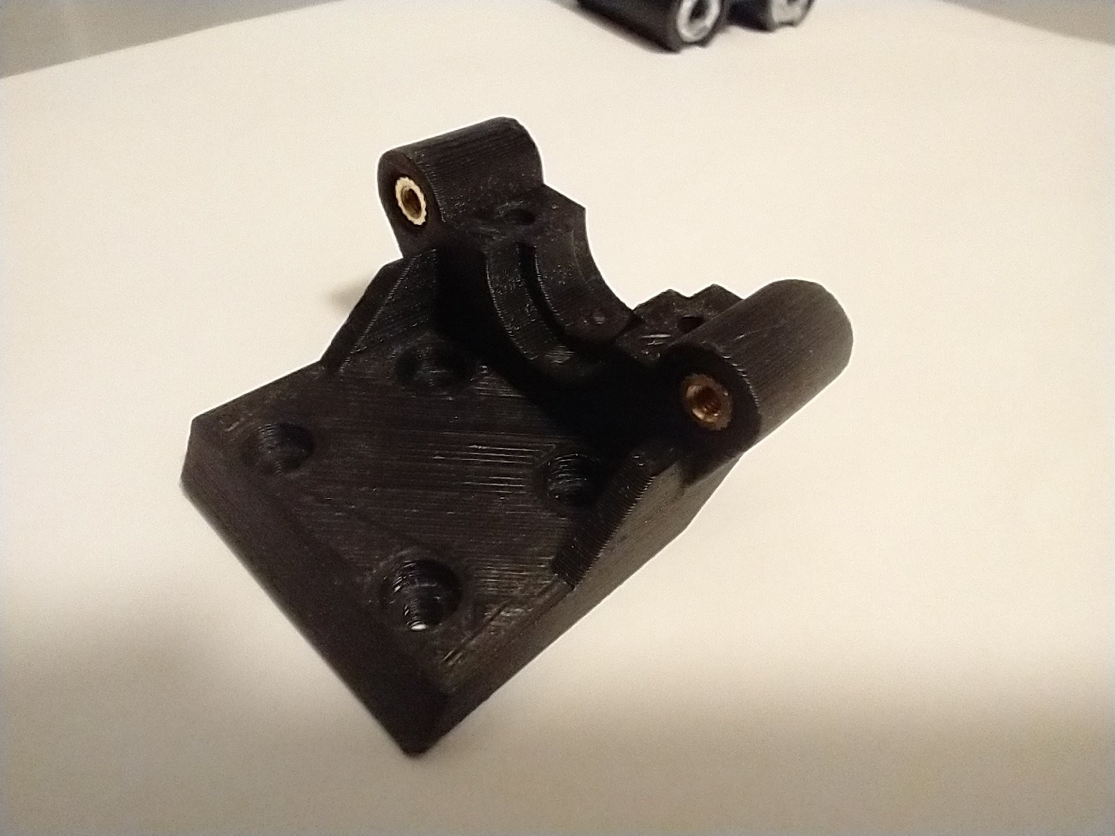
- 1x Hotend mount (use a heat-resistant material)
- 1x Hotend clamp
-
2Clear the 3D printed holes as required
The holes must be clear to allow M3 screws to pass through easily.
-
3Clean and lubricate the two LM6LUU bearings.
The bearings were cleaned using a bath of kerosene and 99% isopropyl alcohol, respectively. White lithium grease was used as the lubricant in this project.
-
4Insert to the bearings into the X-carriage, ensuring that both ends are flush with the sides of the carriage.
Press against a hard flat object to push the bearings into the carriage. Do not press against the black runner/plastic seal.
-
5Use a soldering iron to press the 12* heat-set inserts into the X-carriage and hotend mount
![]()
- The inserts should sit below the surface of the part, and but do not need to be aligned with the chamfers.
- Please note that the inserts used to secure the hotend clamp should be 'pulled' into their respective hole using a long screw (the M3x25 or M3x30 screws will suffice) at the same time that the nut is heated. This will help ensure that the hold remains clear througout the process, as the angled face at the rear of the hotend mount may cause excess plastic to build up in front of the insert.
- Insert the screw through the front of the hotend mount until the end protrudes from the rear side.
- Attach the heat-set insert to the end of the screw, engaging only 2-3 threads to minimize heat transfer into the screw
- Pull the heat set insert against the plastic using the screw, in the direction of the hole.
- While still pulling the insert against the plastic, use the soldering iron to heat the insert.
- As the plastic softens and yields, pull the insert until the top edge is covered by plastic
- Quickly unscrew the screw and then pull the screw directly out of the hole (without turning the screw) to ensure that the hole remains clear.
- The 'side' heat set inserts of the X-carriage are not shown in the images as the printed model was an earlier iteration with the side hole on the opposite side only.
- *The number of heat set inserts used will vary based on the users requirements. 12 inserts were used in this project
![]()
![]()
-
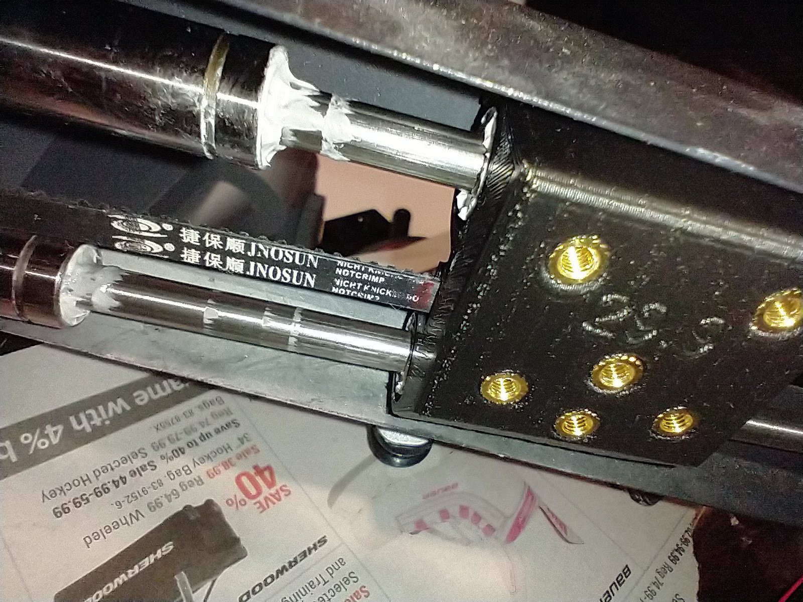
6Mark the belt locations on the left and right of the stock carriage using a marker.
A red permanent marker was used in this project. This will help ensure that the belt tension can be duplicated, tightened or loosened on re-assembly. The image below is post-carriage replacement, but the marks are still visible. The paper underneath is to prevent contamination of the build surface from the grease. The two additional bearings shown in the image are not required.
![]()
![]()
-
7Remove the X-axis cover
This is held on by four Phillips head screws: two on the end of the cantilevered arm, one on the top, just inside of the tower, and one below, just inside of the tower. The top and bottom screws can be left on, but will make assembly more difficult. Note that the X-Axis endstop is connected to the cover, so the cover cannot be moved far away from the printer
-
8Remove the X-axis pulley screw, located at the end of the end cap.
Use the 2.5mm hex key
-
9Move the X-axis pulley out of the way
It is still connected to the belt, which has not been removed from the carriage at this point. This will keep it out the way for subsequent steps.
-
10Remove the belt from the carriage
A flat blade screwdriver may be beneficial. Please note that the belt is looped behind the retaining tab.
Monoprice Select Mini V2 Modular Toolhead
The stock toolhead/carriage is replaced with a modular system that allows quick and easy toolhead changes.


Discussions
Become a Hackaday.io Member
Create an account to leave a comment. Already have an account? Log In.