-
21Re-position the X-axis pulley inside the end cap
Ensure that the drive gear inside the tower is still attached to the belt, and adjust as required.
-
22Secure the X-axis pulley to the end cap
Apply pressure on the pulley towards the end cap and secure the pulley to the endcap using the retaining screw. Ensure that the screw is not making contact with the belt.
-
23Re-attach the X-axis cover
This is not required, but this step was completed for this project to maintain the aesthetics of the original machine.
-
24Re-test the movement along the x-axis by homing the axes
If no issues are found, continue. If issues with the movement are found, diagnose and correct the issues before proceeding.
-
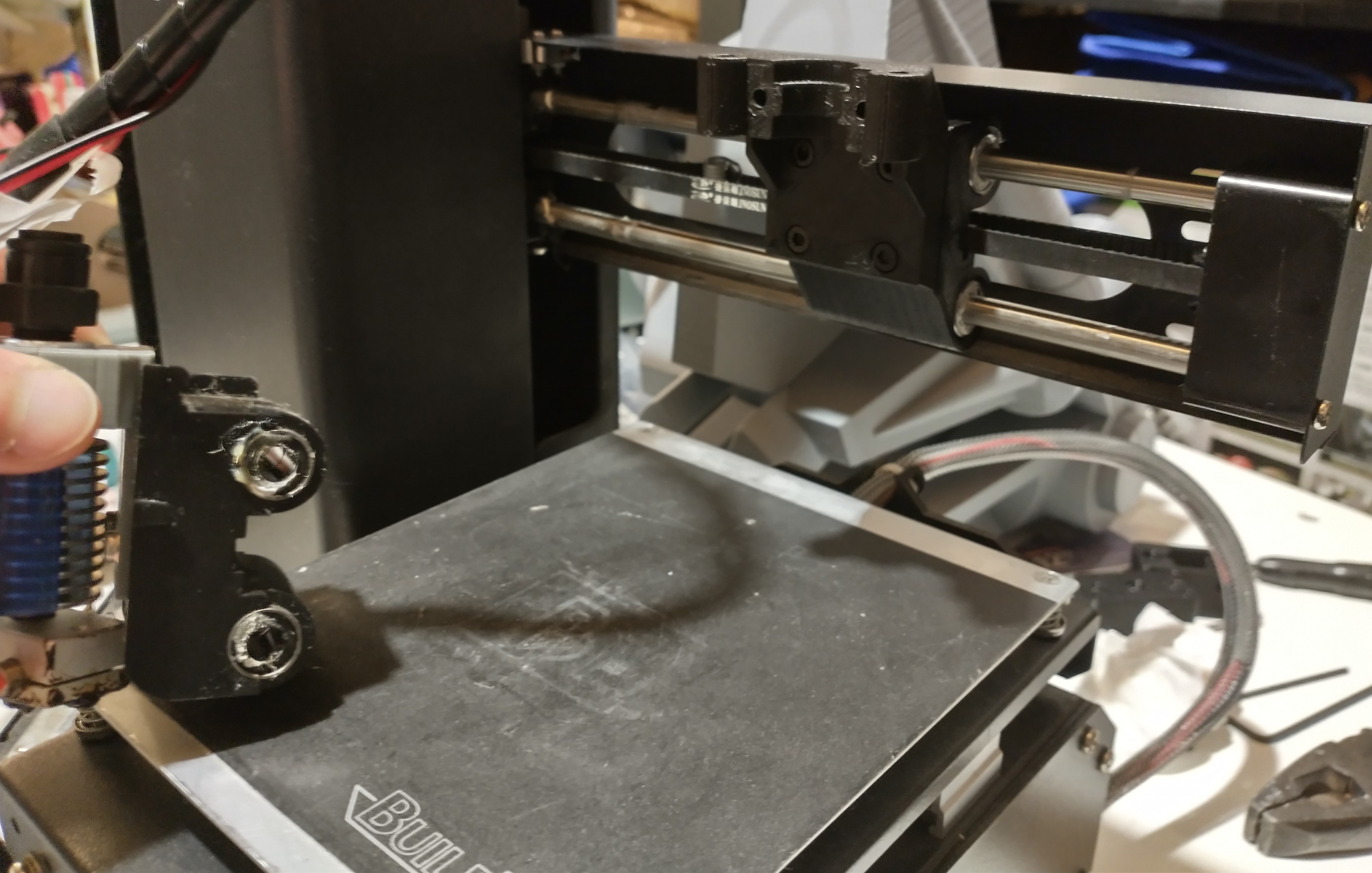
25Attach the hotend mount
Use 4x M3x8 screws. The old carriage and hotend assembly can be seen on the left side of the image.
![]()
-
26Position the hotend and hotend clamp
Add the hotend to the groove mount and clamp in place using the hotend clamp
-
27Secure the hotend
Insert 2x M3x30 screws through the hotend clamp and secure the clamp and hotend to the hotend mount
-
28Re-adjust the bed level as required
-
29Add the X-axis offset
Optional: Use the offset if the hotend mount or extruder contacts the tower before the X-axis endstop is triggered. Adjust the thickness of the offset as necessary. Secure to the carriage using the appropriate sized M3 screw (see components to determine the required length)
Monoprice Select Mini V2 Modular Toolhead
The stock toolhead/carriage is replaced with a modular system that allows quick and easy toolhead changes.

Discussions
Become a Hackaday.io Member
Create an account to leave a comment. Already have an account? Log In.