The key component in this mode is predictably the Mem2Hex described here. This is how the component is hooked-up:
hexout: mem2hex port map (
            clk => hex_clk,
            reset => reset,
            --
            debug => hexout_debug(15 downto 0),
            --
            nRD => nRead,
            nBUSREQ => hexout_busreq,
            nBUSACK => hexout_busack,
            nWAIT => nWait,
            ABUS => ABUS,
            DBUS => DIN,
            START => button(0),
            BUSY => LDT1Y,            -- yellow LED when busy
            PAGE => page_sel,        -- select any 8k block using micro DIP switches
            COUNTSEL => '0',        -- 16 bytes per record
            TXDREADY => tx_ready,
            TXDSEND => hexout_send,
            CHAR => hexout_char
        );
Few notes:
- I copied the VHDL and microcode (split) because I expected more changes to do to the design, but in the end they were mostly cosmetic.
- clk (IN) - 12.5MHz, but this is not critical, it can go from 0 to 50MHz.
- reset (IN) - Anvyl has no "hardware reset" button, so pressing all BTN together is a "reset"
- debug (OUT) - state from microcode controller driving the design is output and can be shown on 7seg LED (useful to single step through microcode)
- nBUSREQ (IN), nBUSACK (OUT) - Z80 syle DMA signals.
- nWait (IN) - there is a common WAIT state generation circuit shared by Mem2Hex and Hex2Mem (described above)
- ABUS (OUT), DBUS (IN) - connected to outside world, along with nRD
- START (IN) - triggered manually (see my finger on the button in video below :-) )
- PAGE (IN) - original component supports selecting any combination of 8k pages. I ran out of switches so I combined 2 bits per DIP to configure the memory to be output, so it is 16k blocks ("page_sel")
- COUNTSEL (IN) - allows 16 (0) or 32 (1) bytes per record.
- TXDREADY (IN) - handshake signal for character output. Microcode waits for this signal to go high before next character is emitted.
- TXDSEND (OUT) - if TXDREADY is high, then a character is put into outside buffer and this signal driven high. The UART par2ser implements the reverse side of this protocol. A FIFO could be injected between them.
- CHAR (OUT) - ASCII code of the HEX stream generated appears here.
Here is how the send character handshake appears in the microcode:
        // "UART" is supposed to signal TDXREADY = 1 when presented 0x00 or when serial trasmit is done
emit:        if TXDREADY then next else repeat;    // sync with baudrate clock that drives UART
        if TXDREADY then next else repeat;
        if TXDREADY then next else repeat;
        if TXDSEND then return else return;
TDXREADY is checked 3 times in a row to prevent any clock domain glitches. Finally, the TXDSEND is checked, but this condition is hardcoded to "1", means it will always return to the caller at this point, but a simple comparator is hooked up to look for check of this condition to generate the send pulse:
-- hack that saves 1 microcode bit width
TXDSEND <= '1' when (unsigned(m2h_seq_cond) = seq_cond_TXDSEND) else '0';
Sanity check for I/O:
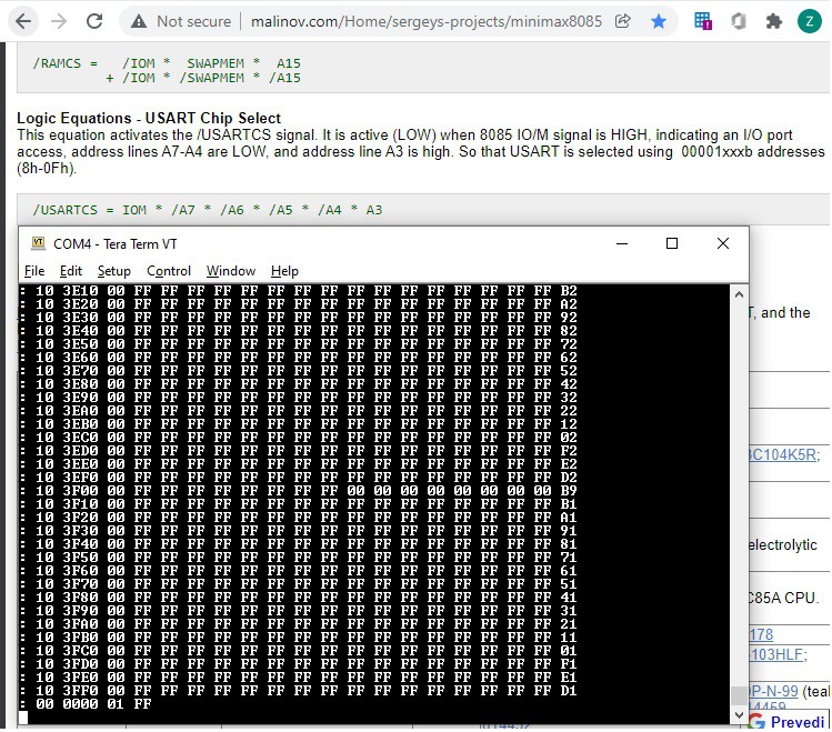
Reading the I/O space can give some indication if it "sniffs right", like in this case. The only IC hooked up to I/O space is 8251 UART, which is enabled when address is XXXXXXXX0001XXXX - when dumping out addresses that match it is visible that "something" appears in those locations, while everywhere else the DBUS returns the default float high.

 zpekic
Discussions
Become a Hackaday.io Member
Create an account to leave a comment. Already have an account? Log In.