Close
0%
0%

Audi e-tron with 555

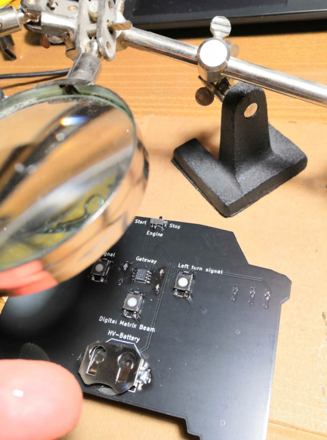
I've made a PCB that represents the front of the Audi e-tron

Similar projects worth following
This PCB has very simple electronics.
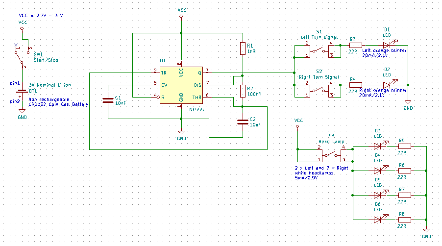
A button to turn on the white LED's for the headlights, and two buttons that represent the turn signals of the Audi e-tron, they blink orange with a 555 chip configured to match the blink frequency of the e-tron.
It also includes a switch to turn off the whole circuit from the coin cell battery.

This decorative PCB on a wooden lasercut stand was a gift for my colleagues that left for another location. 

I took care to have Easter eggs on the product we're working on - the Audi e-tron - to let them not forget the months we worked and struggled together on that project.

I've also let a blank spot on the number plate to stick a personalized Belgian plate with their name on it.

You'll find the design considerations and limitations I had in the instructions.

  • 1 × TLC555CDR Low Power 555 oscillator chip
  • 1 × Tactile switch SPST Button from TE Connectivity
  • 1 × 10uF capacitor 0603 MLCC SMD capacitor
  • 1 × 10nF capacitor 0603 MLCC SMD capacitor
  • 1 × 100kOhm resistor 0603 standard resistor

View all 12 components

  • Silkscreen

    Sami12/14/2021 at 15:15 0 comments

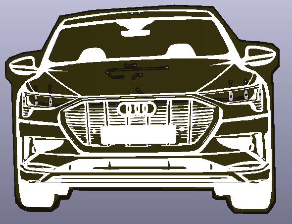
    The silkscreen has been generated by taking a picture of the front of the Audi e-tron, converting it to gray scale and afterwards to black and white.

    After this, I've let it pass by my edge detection algorithm and played with the filter to have the right amount of details of the e-tron.

    After running the new picture in the bitmap converter tool from KiCAD, I had my Silkscreen that I could import on the PCB.

  • First batch

    Sami12/14/2021 at 12:48 0 comments

    Here a PCB with my name on it

    Soldering phase with 0603, I has no flux-remover anymore and could not clean the PCB's. Hopefully it doesn't corrode the pads with time.

View all 2 project logs

  • 1
    Schematics of the PCB

    The schematics is very simple. The only limitation was the CR2032 coin cell battery voltage which is low and can get very low. For this purpose I've used a low powered 555 chip which can work in a range between 2V and 15V with very low current; 250uA.

    I use the 555 chip to drive the orange blinky LED's as a source, the chip can handle 10mA and the LED's only need 2.1V with 5mA of current.

    The resistor and capacitors make the 555 work as an Astable Multivibrator that matches the frequency and ON-time of the Audi e-tron (1.4s Period and a duty cycle of 50%).

  • 2
    PCB and back silkscreen

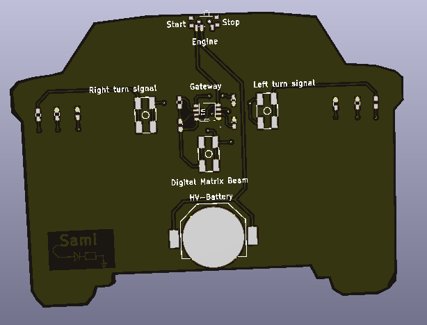
    The PCB edge is cut to represent the Audi e-tron.

    For the backside of the PCB, I chose to name the components and buttons to reference the Audi e-tron. HV battery (for the coin cell), Digital matrix beam for the front white LED's, Gateway for the main computer on board which is the 555 in this case and finally the ON/OFF switch which represent the Engine start button.

    I've positioned the components such that it was easy to push the buttons, to reach the switch and to replace the coin cell battery.

  • 3
    PCB and front silkscreen

    On the front decorative side, you'll find the silkscreen that draws the shapes of the e-tron. I've let a blank spot to paste a Belgian number plate sticker.

    The orange LED's on the extreme left and right side are at the position of the blinkers, and the 4 white LED's on the position of the matrix beam headlights.

View all 4 instructions

Enjoy this project?

Share

Discussions

Similar Projects

Does this project spark your interest?

Become a member to follow this project and never miss any updates