-
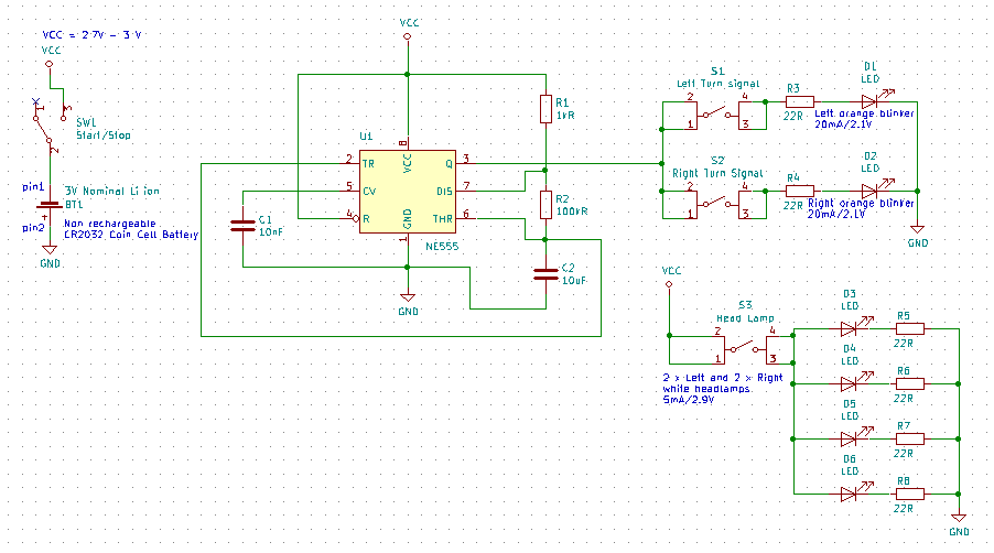
1Schematics of the PCB
![]()
The schematics is very simple. The only limitation was the CR2032 coin cell battery voltage which is low and can get very low. For this purpose I've used a low powered 555 chip which can work in a range between 2V and 15V with very low current; 250uA.
I use the 555 chip to drive the orange blinky LED's as a source, the chip can handle 10mA and the LED's only need 2.1V with 5mA of current.
The resistor and capacitors make the 555 work as an Astable Multivibrator that matches the frequency and ON-time of the Audi e-tron (1.4s Period and a duty cycle of 50%).
-
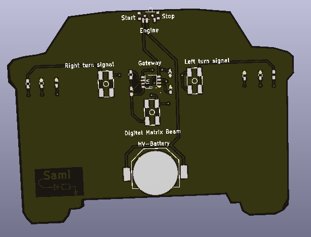
2PCB and back silkscreen
![]()
The PCB edge is cut to represent the Audi e-tron.
For the backside of the PCB, I chose to name the components and buttons to reference the Audi e-tron. HV battery (for the coin cell), Digital matrix beam for the front white LED's, Gateway for the main computer on board which is the 555 in this case and finally the ON/OFF switch which represent the Engine start button.
I've positioned the components such that it was easy to push the buttons, to reach the switch and to replace the coin cell battery.
-
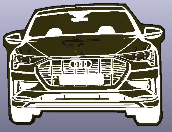
3PCB and front silkscreen
![]()
On the front decorative side, you'll find the silkscreen that draws the shapes of the e-tron. I've let a blank spot to paste a Belgian number plate sticker.
The orange LED's on the extreme left and right side are at the position of the blinkers, and the 4 white LED's on the position of the matrix beam headlights.
-
4Soldering and testing
Everything is easy to solder, I chose 0603 sized components and the 555 is a SOIC sized 8 legged chip. Before turning the "engine" ON, I would recommend to measure the voltages on the IC and control the right position of the coin cell battery.
 Sami
Sami


Discussions
Become a Hackaday.io Member
Create an account to leave a comment. Already have an account? Log In.