deʃhipu
-
Version Two
01/14/2022 at 14:15 • 0 commentsSelect all, cut.
![]()
Paste.
![]()
-
Thinking about V2
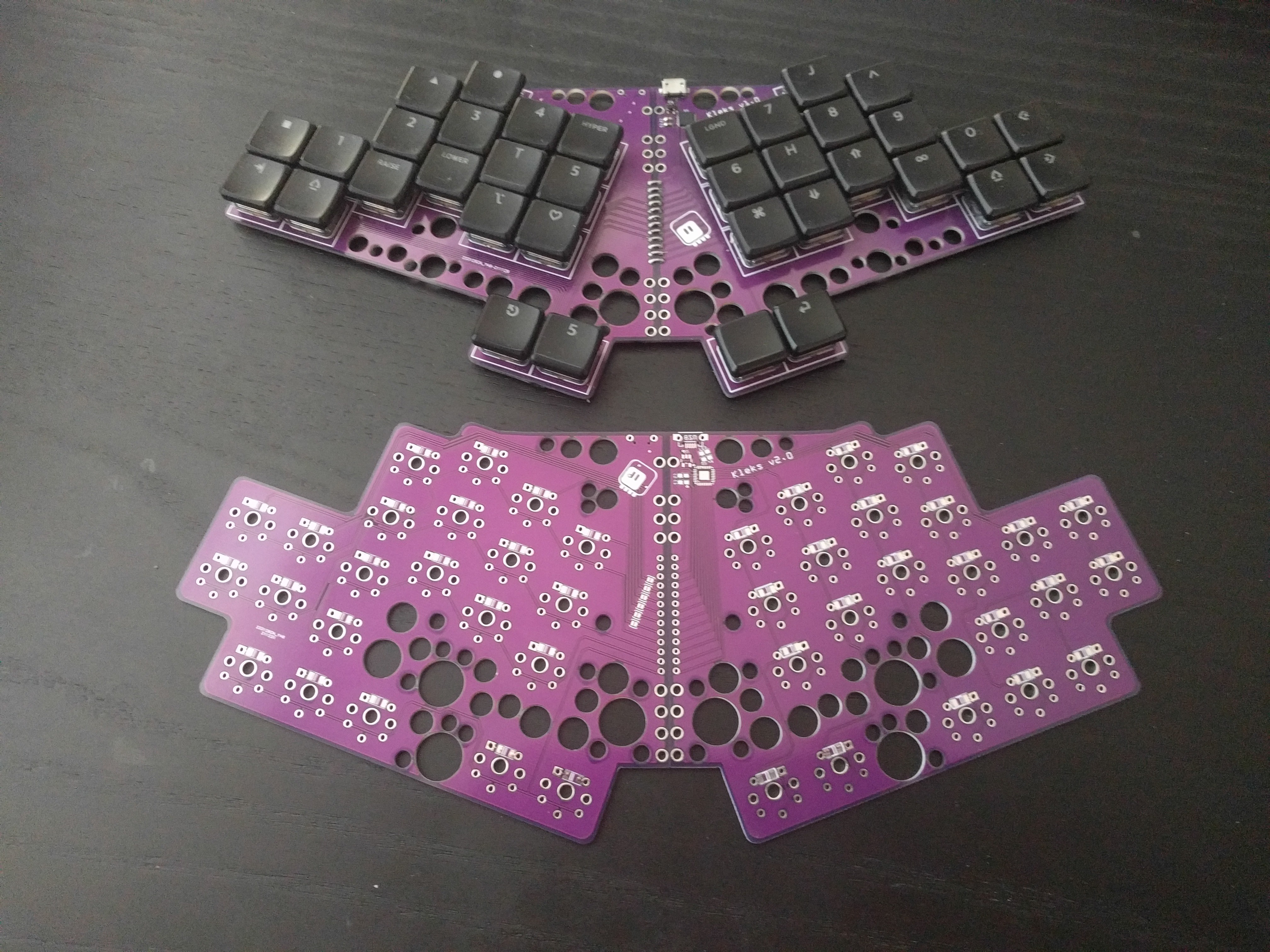
12/26/2021 at 23:00 • 0 commentsI've been using this keyboard some time, and it's close to perfect, but there are several things that could be still improved in my opinion, so I went ahead and re-designed the PCB a little bit.
![]()
![]()
I added a little stagger to the inner columns, because it was a bit hard to reach the T and Y keys. I also lowered the middle finger column a bit, because the stagger there was a bit much. The pinky cluster stays as it is, because it is perfect — I didn't even move it the 3mm needed to align it with the new keys.
I added a cluster for the cursor keys, because having them on a layer is not convenient, and I'm not touch-typing when I'm cursoring anyways. Since the board is by necessity symmetric, I will also have some extra keys on the other side — I will put the rarely used modifier keys there.
Finally, I added a place for a CapsLock LED, though I never use it. But there were free pins, so why not.
The layout will look something like this:
![]()
-
NKRO and BOOT
12/10/2021 at 22:13 • 0 commentsI took the opportunity with this new keyboard and worked a bit on my uKeeb CircuitPython library. With the custom HID descriptors we can have an NKRO keyboard, but there is a small problem: the bitmap device that this uses won't work in BIOS or with legacy KVM devices, as those expect a BOOT device. Fortunately there is a way around that: when the host expects a BOOT device, it must send you a special message telling you that, so we can switch to that protocol when needed.
The support for receiving that message was recently added to CircuitPython in version 7.1.0, so we can now add the NKRO code to the library by default.
If you are interested in the details, feel free to check the library code at https://github.com/deshipu/ukeeb
-
Programming
12/09/2021 at 20:10 • 0 commentsAll that is left is to program it. As usual, I wanted to use CircuitPython, with my ukeeb library. I flashed the bootloader with a JLink through a header I temporarily soldered to the stitches in the middle, and then I flashed the most recent CircuitPython. I'm using the board definition I made for #Fluff M0, because it exposes all the pins of the SAMD21.
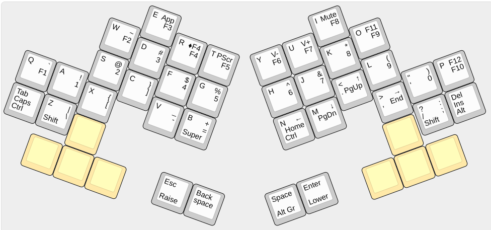
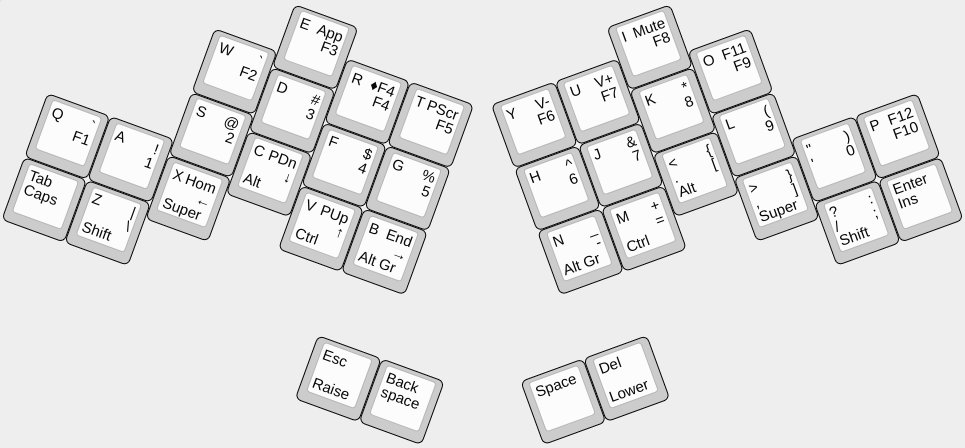
Next it's time to decide on the layout. For now I am using something like this:
![]()
The labels on the bottom of the keys is what happens when you hold the key and press another one. There are two traditional layers, switched with the Raise and Lower keys. One thing I added compared to my previous keyboard, is that if you press Raise and Backspace, you get Lower, and if you press Lower and Space you get Raise — this way you can type with one hand with access to both layers. This helps when playing games.
I'm not entirely happy with the modifier keys yet, I will probably reshuffle them somewhat, and I will probably swap the arrows keys and the home/end and pgup/pgdn layers. Otherwise it works for me.
-
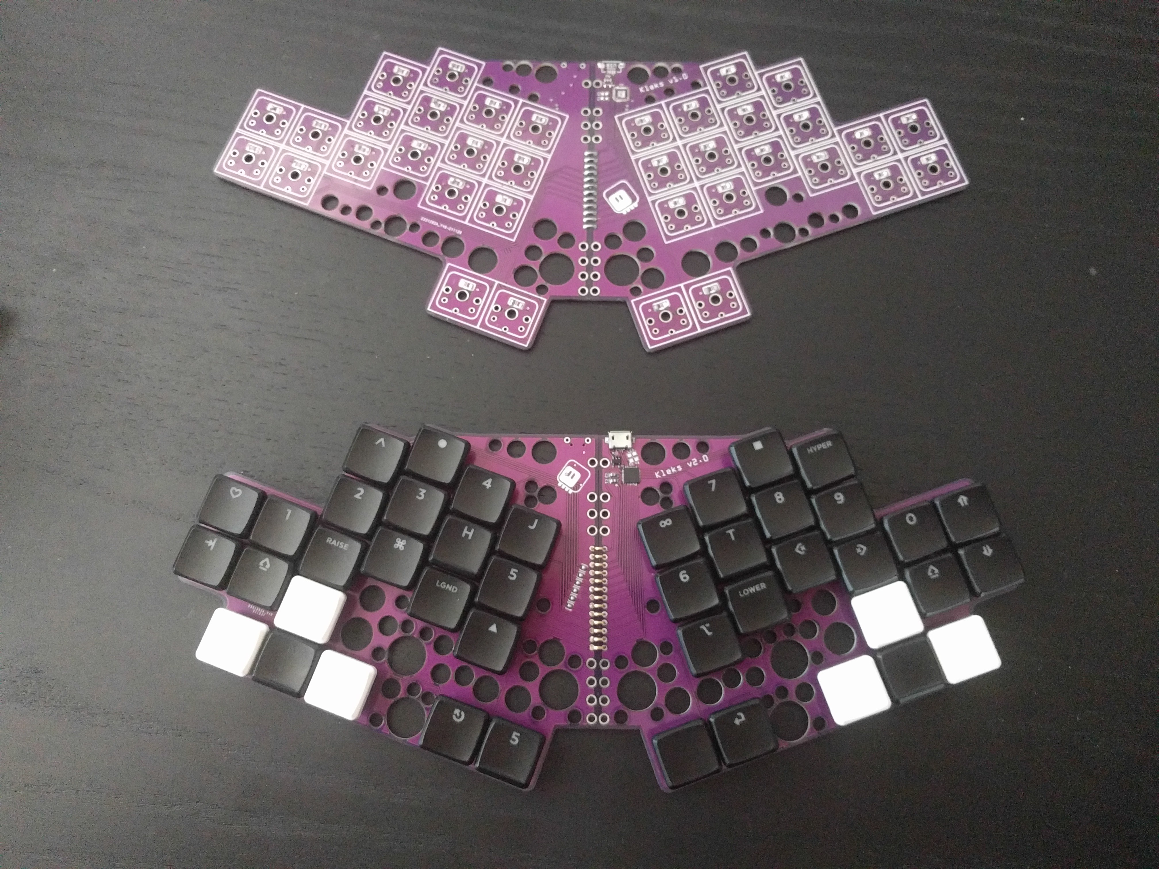
Assembled
12/09/2021 at 20:02 • 0 commentsFirst I needed to test how good the stitching of the two halves together was.
![]()
It tuns out to be pretty good. I didn't even have to use the holes I added to the edges in case there was a need for more mechanical stability. The boards are connected by a male pin header, that was soldered in one side, had its plastic part removed, and then was inserted into the other half and bent into U-shape until both halves were parallel. Then I tinned it with copious amounts of solder, to make it look like the rest of the pads on the board.
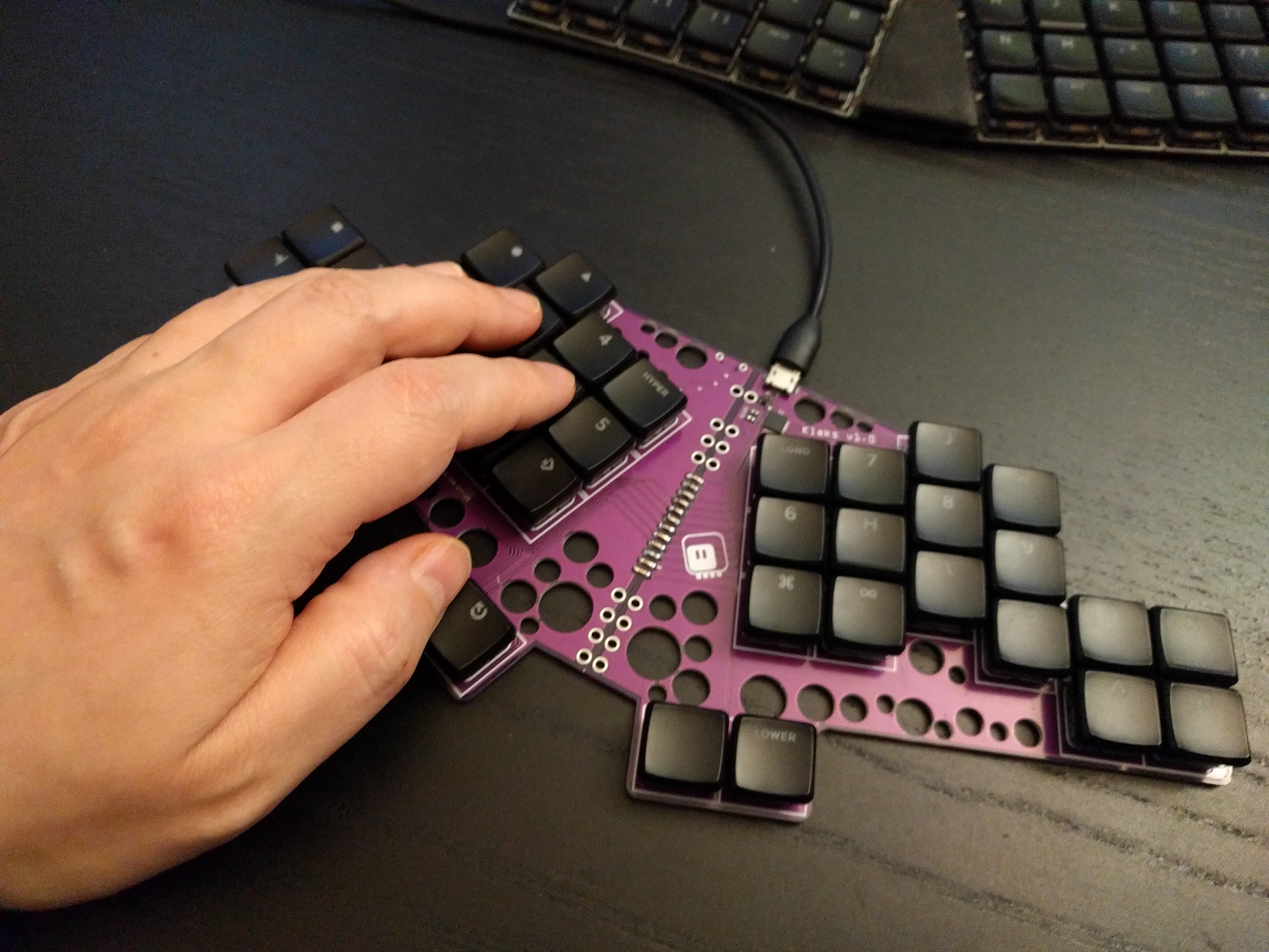
With that done and tested, I soldered the diodes, the MCU and the remaining components. Then I added the Purpz switches and MBK keycaps (somewhat randomly labeled, I'm still waiting for the MBK Legends groupbuy), and we have a keyboard.
![]()
-
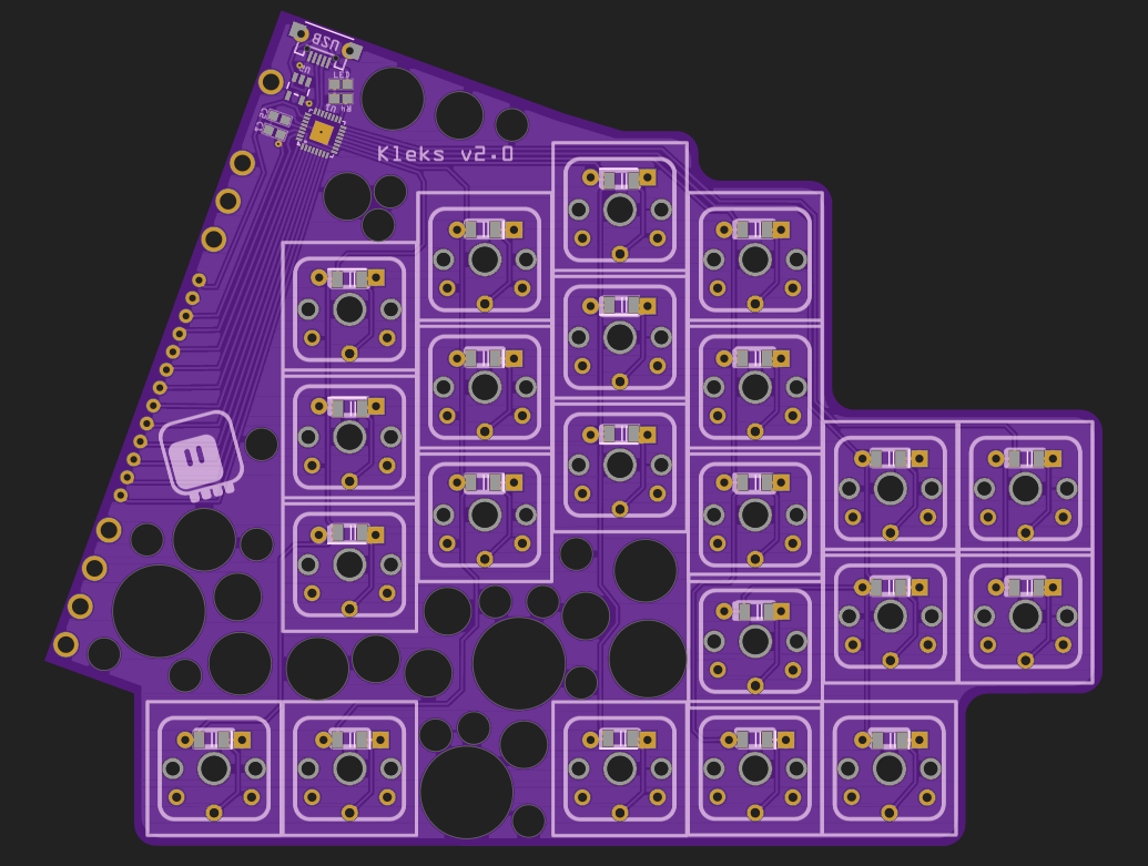
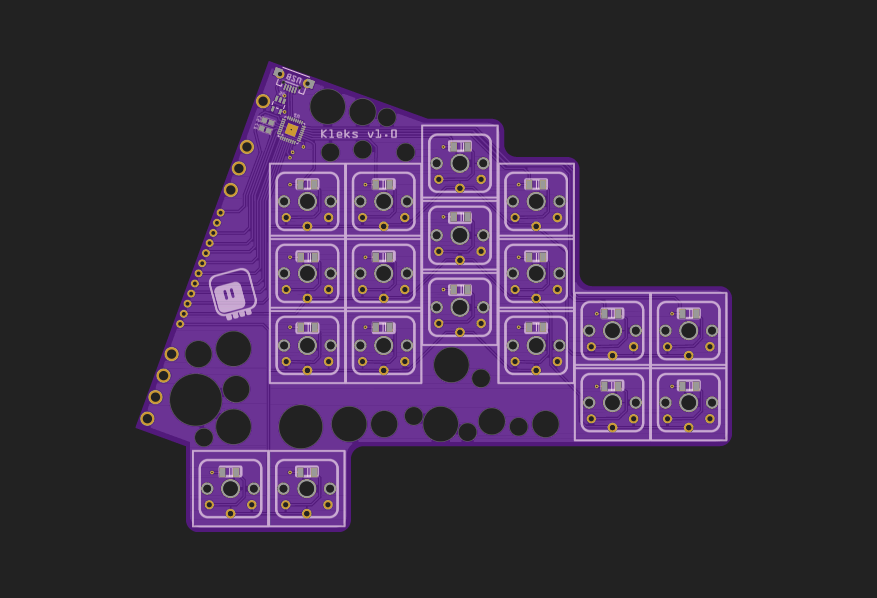
The PCBs
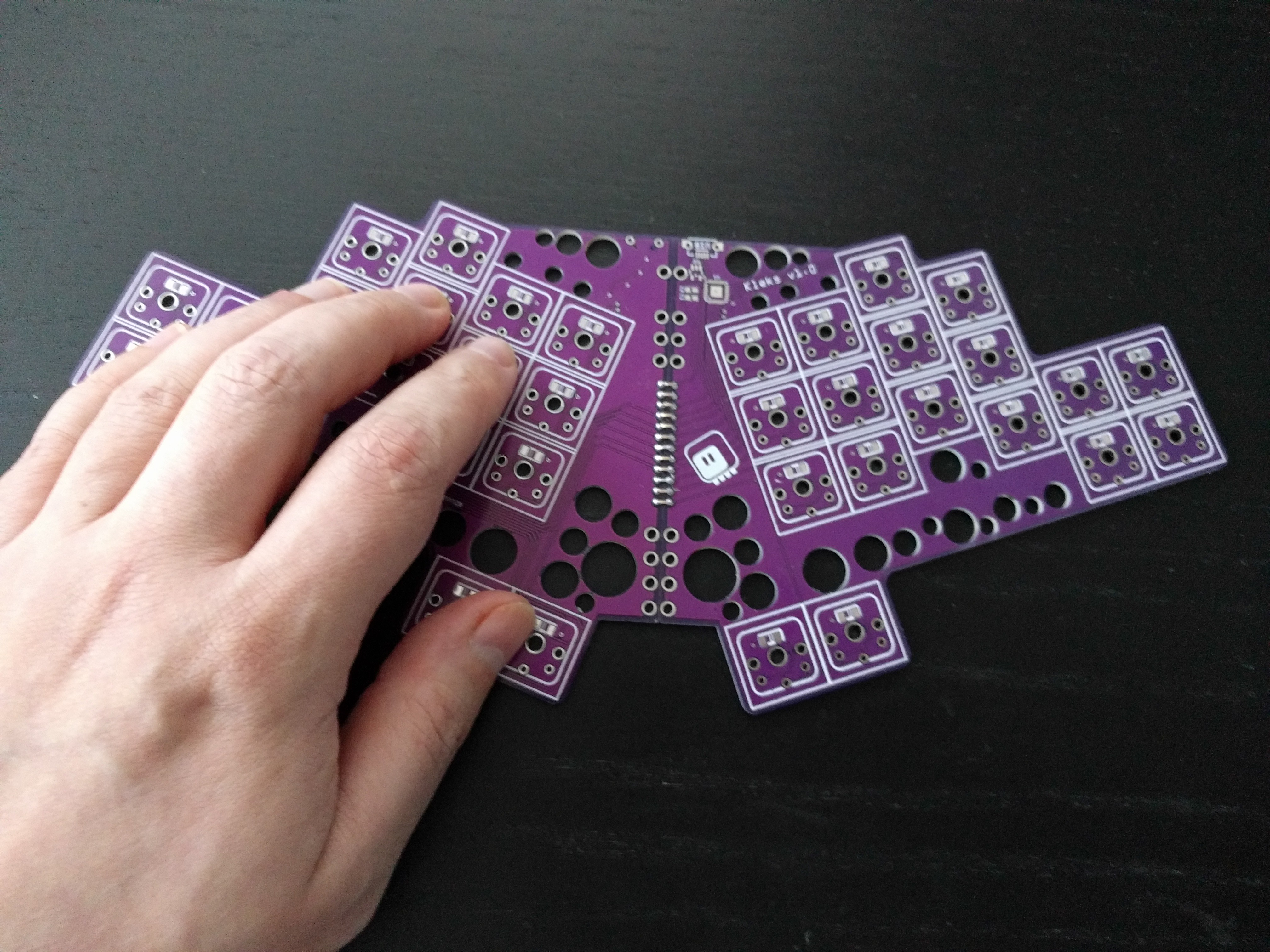
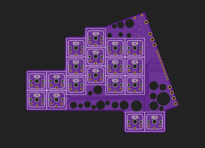
12/09/2021 at 19:56 • 0 commentsI designed the PCB for this keyboard the same way as the two-part split keyboards are often designed: the same PCB is used as the left and right part, with switch footprints on both sides, so that it can be flipped. However, in this case I only have a microcontroller on one side, so all the connections from the other half need to be brought over thorough a connector joining the two sides.
![]()
![]()
Logically the board has three rows and a dozen columns, which means that I need at least nine traces to cross to the other side. I made it 12 by also adding the connectors for power, ground and reset — they are not needed on the other side of the board, but they are useful for programming the board, and this way I didn't have to add a separate connector for this.
And before you ask, yes, the holes are purely decorative. I just like how they look, and that part of the PCB was empty anyways.