Patrick Van Oosterwijck
-
PCBA ordered from JLCPCB
01/09/2022 at 22:10 • 0 commentsI went ahead and ordered PCBs and assembly from JLCPCB. There was a little more friction to the process than I had hoped.
The service is picky about the formats for the BOM and placement files, and it seems some parts that looked available on LCSC were actually not available for the assembly service, so I had to select other ones. I would recommend that if you intend to use this, you start from the "Basic" parts library. Because I didn't, I also had a good number of special parts that added cost to my order. Oh well, lesson learned.
Unfortunately the position data for assembly exported from KiCad also couldn't be directly ingested by JLCPCB, it took some manual massaging in a spreadsheet to get it right.
But in the end, getting 5 prototype PCBs produced, fully SMT assembled and shipped for about $72 is still a very good deal!
-
KiCad prototype design
01/07/2022 at 19:46 • 0 commentsWell, I couldn't help myself I guess. 🙂
KiCad 6 had just been released, I was on vacation and sometimes needed to fill some idle time, so I decided this was a nice small project to get some more KiCad experience. Who knows, maybe if it works well, it might become a product too.
To make the LTSpice concept more practically useful, a couple of things needed to be added:
- Over discharge protection
- Preventing the battery from back feeding the 555 charger
- Under temperature protection
- A battery heater to get the battery up to temperature for charging
These needed to be added with minimal circuitry and cost to stay true to the concept that this is a 555 based circuit first and foremost.
A couple of limitations remain:
- Maximum input voltage is 16V due to the 555 input voltage limit. This is just fine, but something to keep in mind when choosing a solar panel. I switched to the SA555 to get wide temperature range for outdoor use.
- The input source needs to be a "weak" source like a solar panel. Since the switching depends on the input voltage drooping when loaded, a strong source that doesn't droop would probably burn something up. So this shouldn't be used with large powerful solar panels or wall power.
- No charge current limiting. Keep the solar panel small enough to limit the current to 1A or so.
- No over temperature protection.
I implemented it with these features:
- A board stuck to the back of an 18650 battery holder that will hold a LiFePO4.
- Screw terminals for VIN (solar panel) and VOUT (load switch protected battery voltage).
- A pot for adjusting the MPP voltage to what's ideal for the panel.
- NTC thermistor and two heating resistors on the PCB. Battery heating also adjusts to the same MPP voltage as charging does!
I'm quite happy with how such a basic and cheap circuit can do all this.
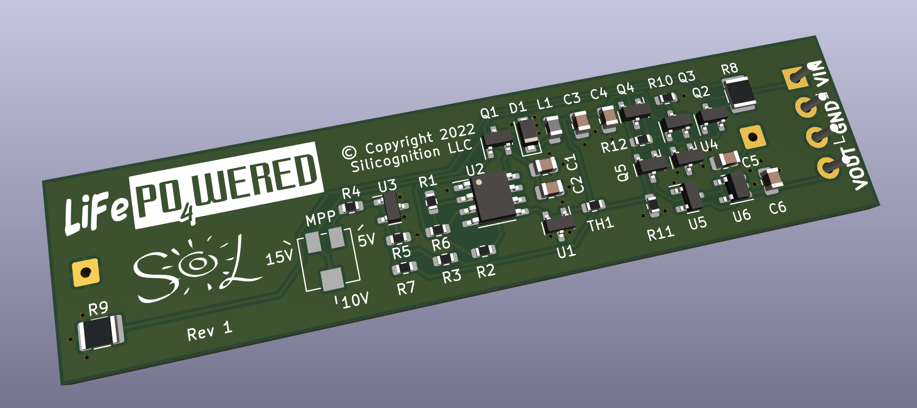
Here's the beautiful 3D view generated by KiCad:
![]()
The pretty logos were probably not necessary for a prototype that may never make it to production, but I felt it was an important part of the learning experience to see how well KiCad handles these things. And to be honest, I was a bit disappointed. There is a function to import SVGs but when I tried it, I would just get white boxes. I had to resort to using this Inkscape plugin to make it work.
Next, I think I'm going to try JLCPCB's assembly service to get some prototypes and see how that works. This should be a good test since all the parts are on LCSC anyway.
-
Have fun with it!
12/10/2021 at 23:08 • 0 commentsThis was a fun circuit to design, and it's not entirely frivolous!
In these times of chip shortages, it can be very useful to base a design on bog standard generic parts that are produced by many manufacturers, such as the 555 and TL431 used in this design, versus doing a design requiring specific components that may only be available from a single source.
You can download the file and play with it in LTSpice, it's a fun way to learn about simulation, and it can give you a nice feel for how the circuit works. Try to change the input voltage V1 or source resistance R5 and see how it affects operation. Or vary the load and see what happens. Or change R3 and see how it affects the MPP voltage.
I don't really have any plans to turn this into actual hardware, but it's tempting just to see how well it works in reality. I guess I may do it if there's enough interest!
555 MPP solar charger
A very simple, low cost MPP solar charger built around the venerable 555 timer