 Mr-Mime
-
1Make some space
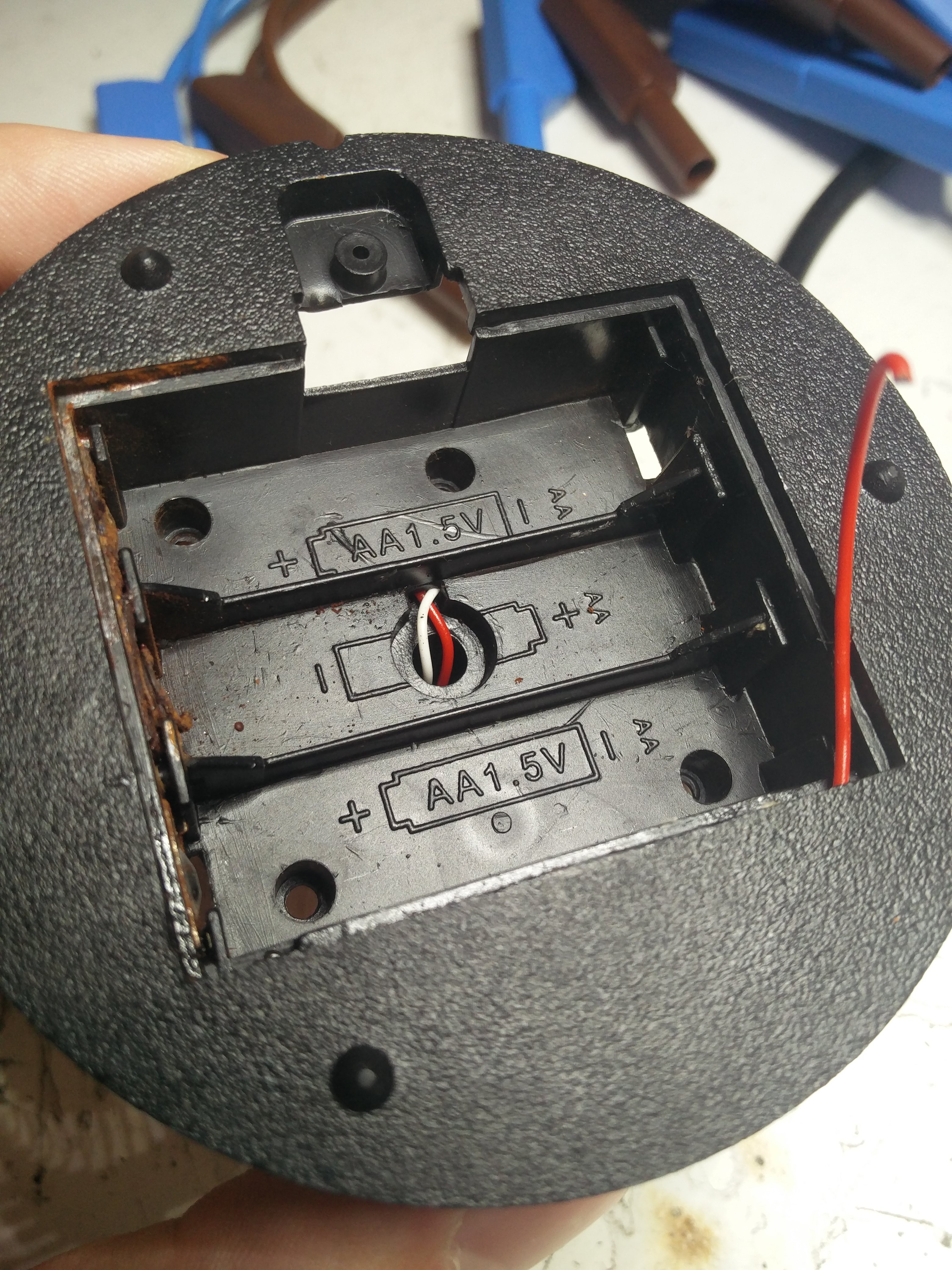
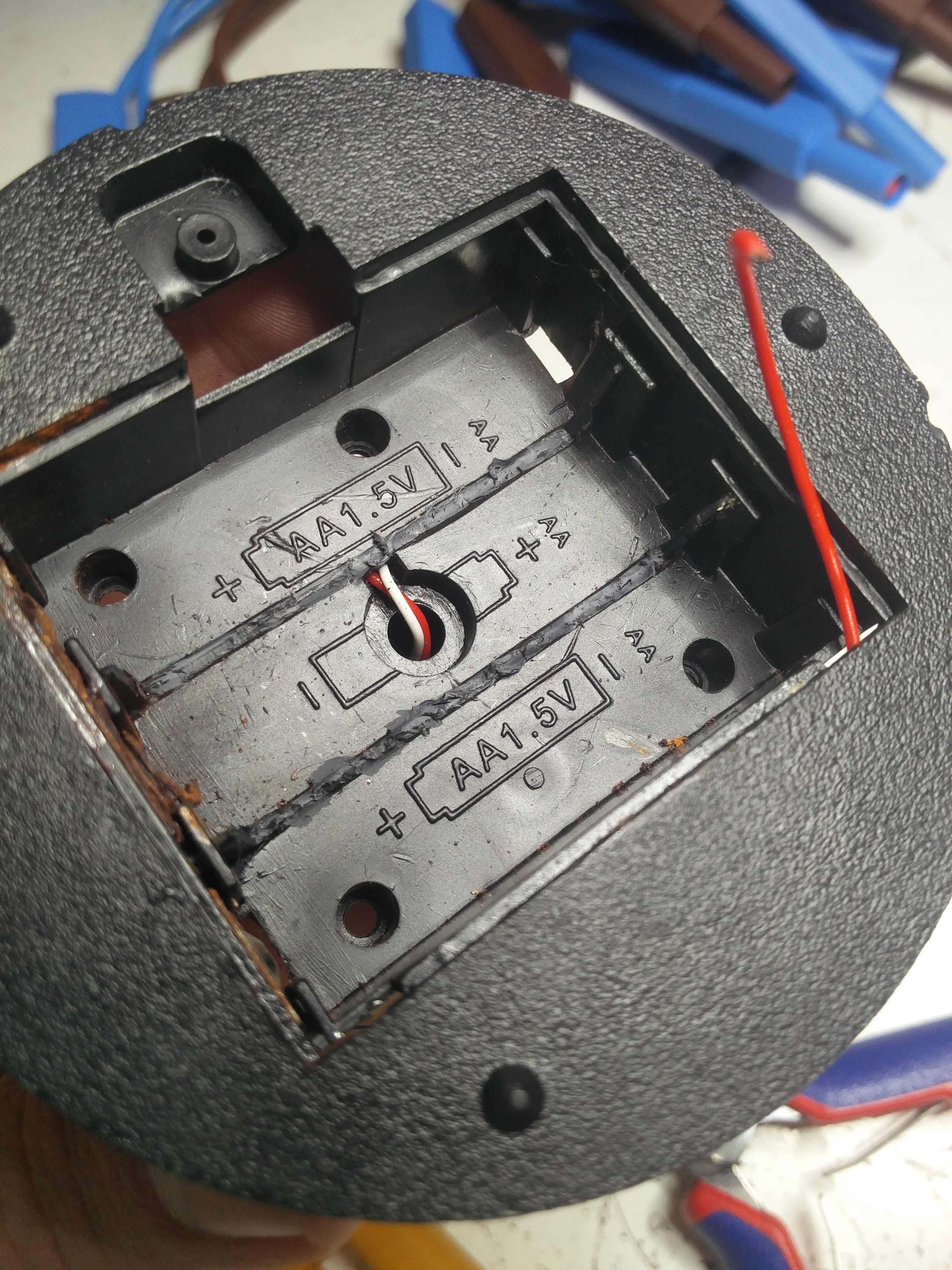
To have more space available I removed the "separation plastic parts" of the battery holder.
Before After ![]()
![]()
-
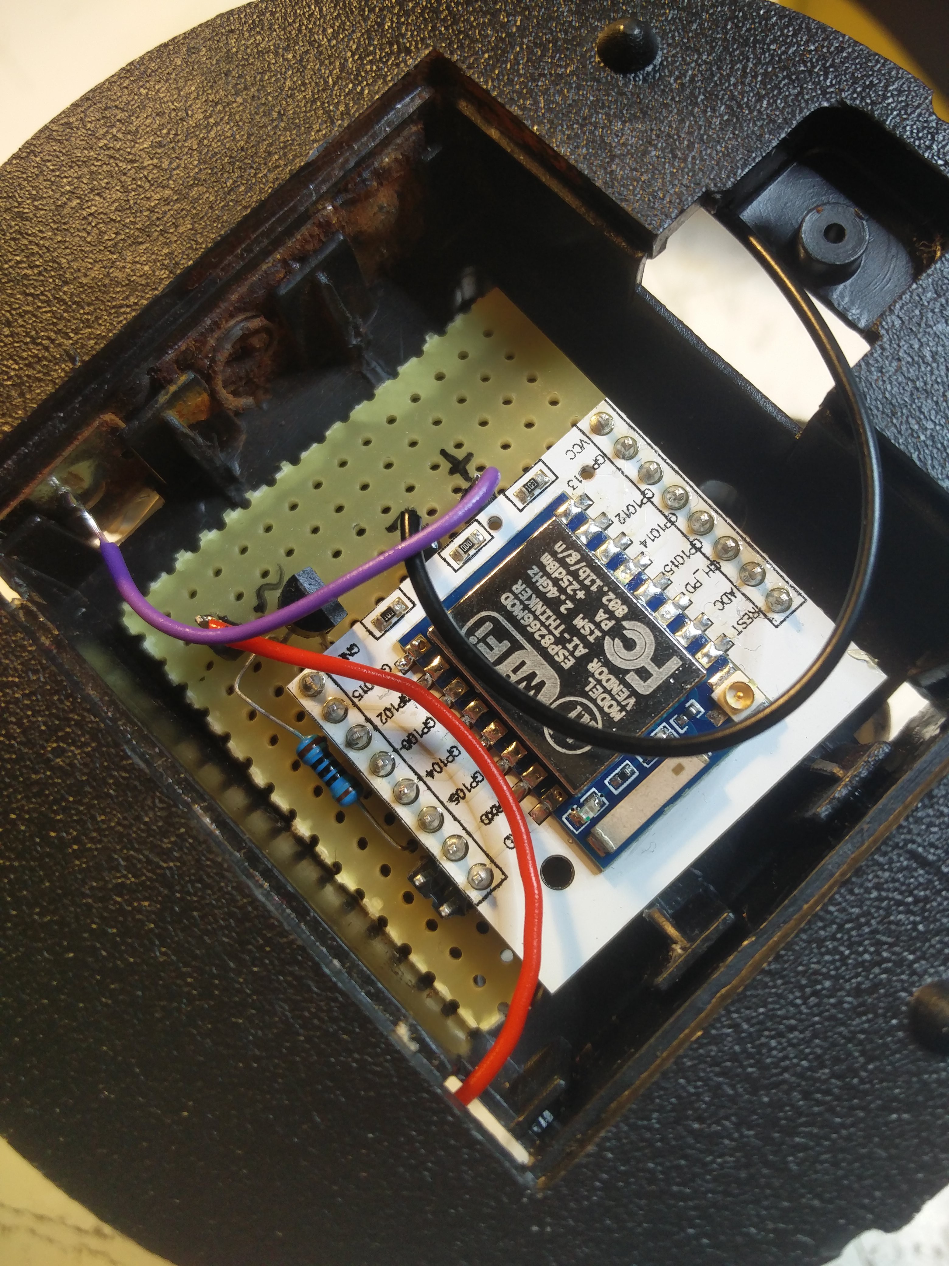
2Solder
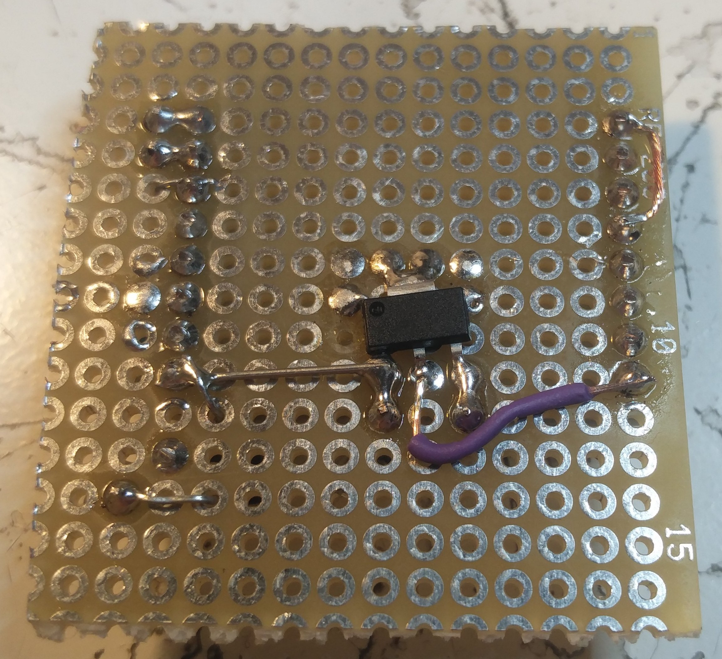
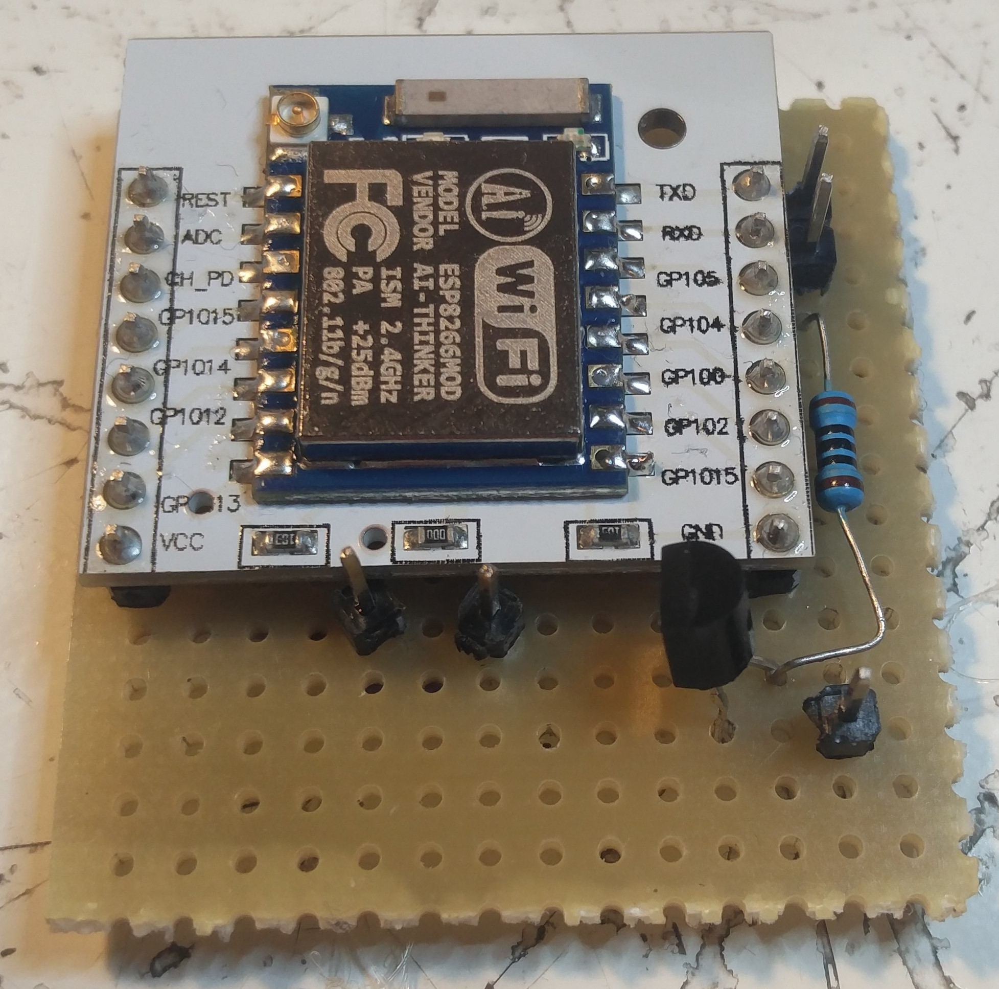
Next I soldered the components on a small perfboard, based on the schematic.
To connect power and the siren I exposed some single male pins, to which the wires will be soldered later.
![]()
![]()
-
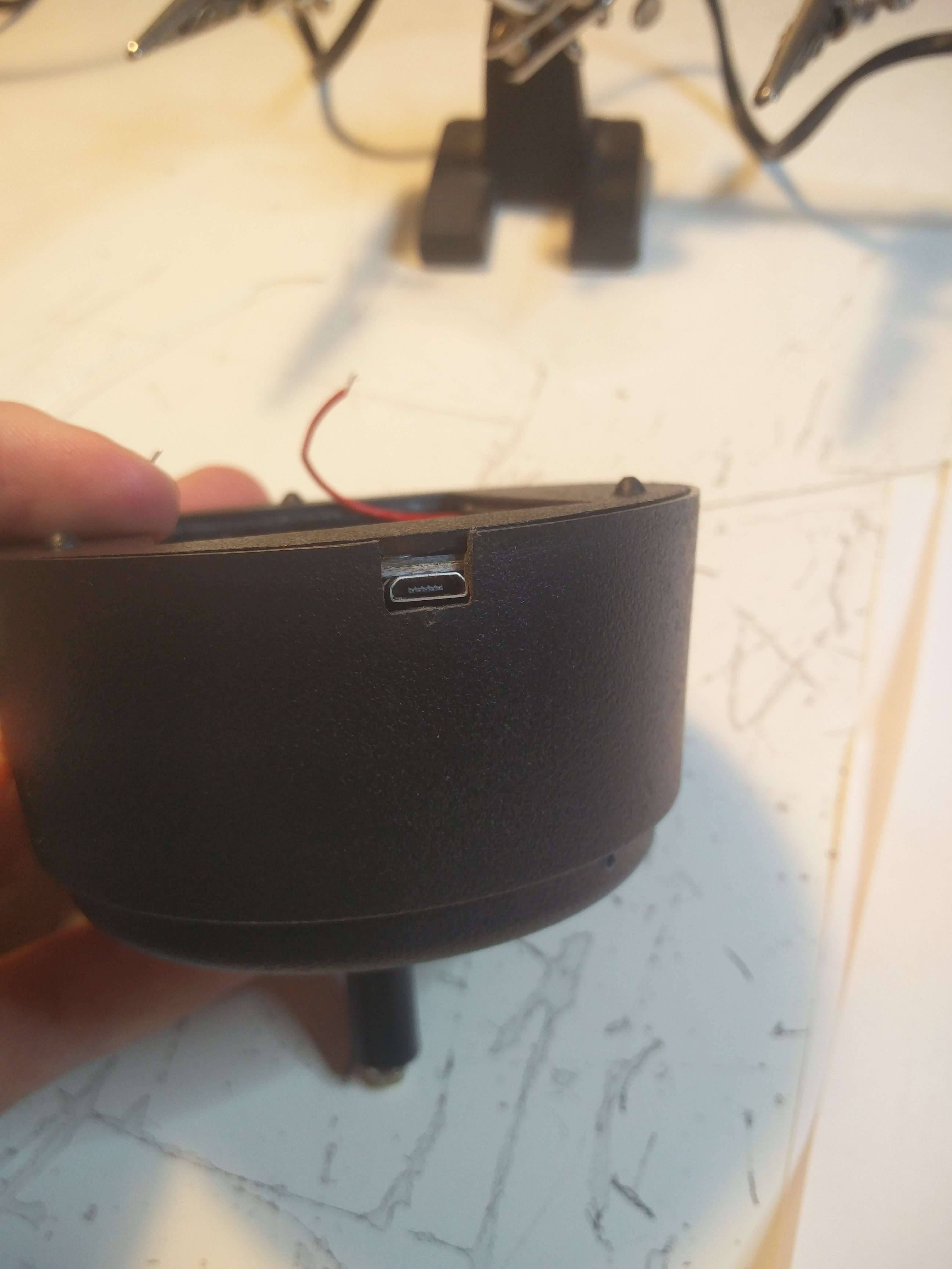
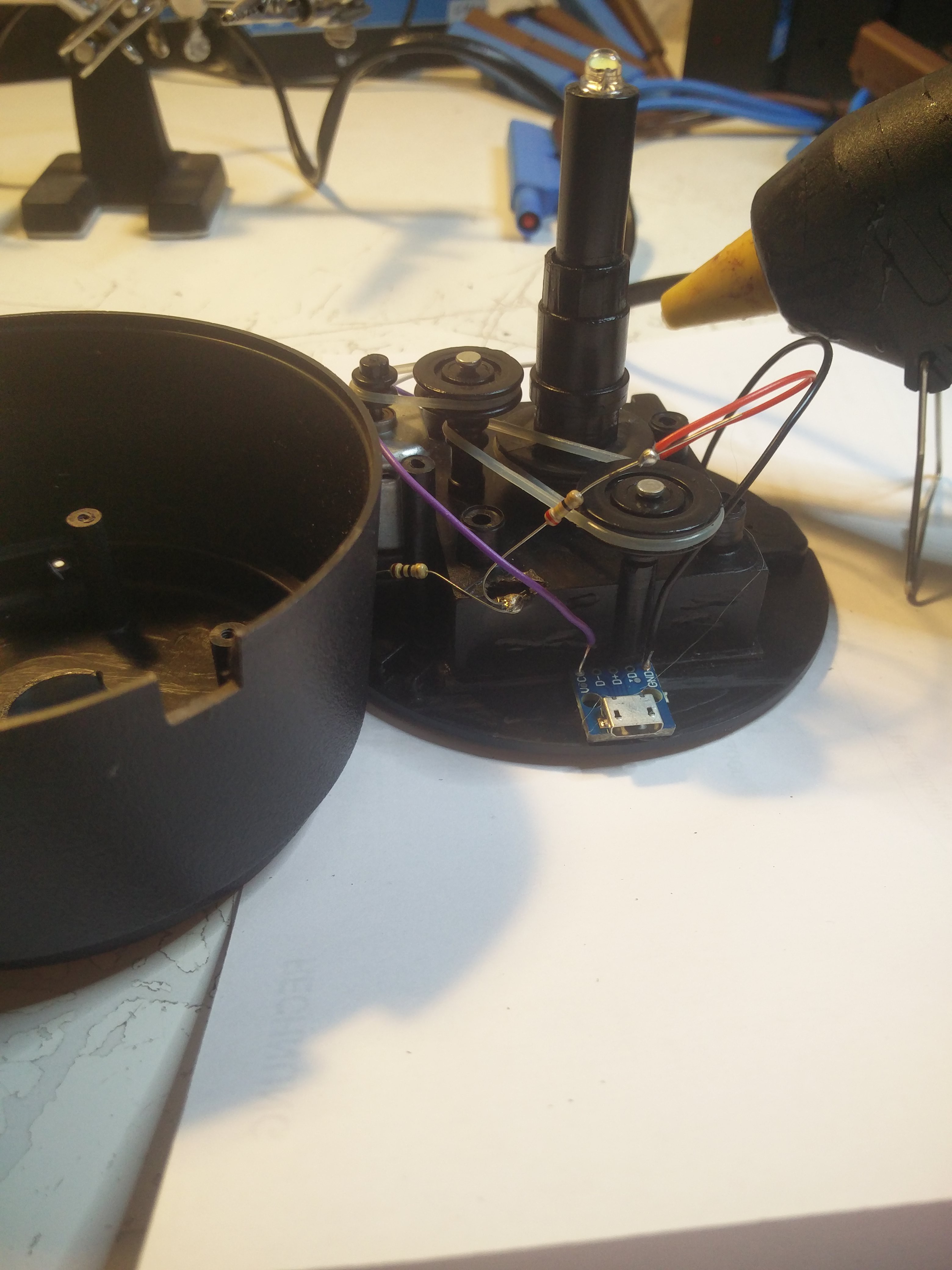
3Add micro usb connector
IMO the opposite side of the switch, is the best place for the power input.
I simply used some hot glue to attach the small board. I know not the best method, but as it perfectly fits it can not move forward or backward when (un-) plugging the cable, thus it holds (for now...)
I also made a small cutout in the outer case to expose the connector.
![]()
![]()
-
4Final assembly
Then I connected all wires that needed to be connected.
5V from micro usb to one connector of the switch, other connector of the switch to the 5V on the board.
GND from micro usb to GND on the board.
The connection to the siren to the exposed pin of the transistor.
Then I stuffed the board in the battery case and closed it.![]()
Discussions
Become a Hackaday.io Member
Create an account to leave a comment. Already have an account? Log In.