 AlliedEnvy
Next up is sequential logic. We could make our own from ANDN gates, but since we have an RS latch already, this would be wasteful. We just need to figure out how to set the inputs to get our desired behavior.
Let's look at our truth table again:
| !R | CE | C | Th | !Tr | Set | Reset |
|---|---|---|---|---|---|---|
| 0 | x | x | x | x | 0 | 1 |
| 1 | 0 | x | 1 | 1 | 0 | 1 |
| 1 | 0 | x | 0 | 1 | 0 | 0 |
| 1 | 0 | x | x | 0 | 1 | 0 |
| 1 | 1 | 0 | 0 | x | 0 | 0 |
| 1 | 1 | 0 | 1 | x | 0 | 1 |
| 1 | 1 | 1 | x | 0 | 1 | 0 |
| 1 | 1 | 1 | x | 1 | 0 | 0 |
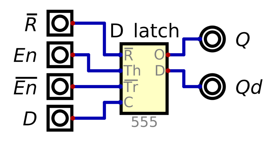
We'd like to create a basic D latch with an enable pin and a data pin. Data should be passed through when enable is high, and latched on the falling edge of enable. A reset pin would also be nice.
Clearly, !R should be our reset. We can combine Th and !Tr as our enable, if we treat Th as En and !Tr as !En, making sure to always drive them opposite to each other (we can use an inverter for this if needed). C becomes our data pin.
Latches are nice, but what would be nicer is a flip-flop. We can cascade two of our latches, with opposite clock polarities, to create a flip-flop:
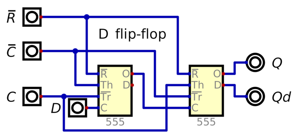
Note that the first latch is of opposite polarity to our standalone D latch, to allow the flip-flop to clock in data on the rising edge of the clock signal.
We now have all the basic building blocks needed for our clock.
Discussions
Become a Hackaday.io Member
Create an account to leave a comment. Already have an account? Log In.