 AlliedEnvy
The clock will use 7-segment LED displays for the time. We need to decode the state of the Johnson counters into one output per segment.
The first task is to determine how to decode the bits of the Johnson counter into individual one-hot outputs. (We could, if we wanted, make a 4017 out of 555s this way).
Here are the ten states of our decade counter (state number down the side, output along the top. !4 is on both sides for clarity.
 _     _
 4012344
0-_____-
1--____-
2---___-
3----__-
4-----_-
5_-----_
6__----_
7___---_
8____--_
9_____-_
We can decode a state by detecting the rising edge (0-4) or falling edge (5-9). This is an ideal match for our ANDN gates -- one input detects the high of the edge, and the other detects the low. Furthermore, we can sometimes decode multiple states at one time by skipping outputs. For example, O0&!O3 decodes 1|2|3.
Now that we can determine specific states, we need to decode to our seven segment display. Traditionally the segments are labeled a through g, going clockwise from 12:00 and g in the center. Another ASCII diagram:
 a   _       _   _       _   _   _   _   _
fgb | |   |  _|  _| |_| |_  |_    | |_| |_|
edc |_|   | |_   _|   |  _| |_|   | |_|   |

a = ~(1|4)
b = ~(5|6)
c = ~2
d = ~(1|4|7|9)
e = 0|2|6|8
f = ~(1|2|3|7)
g = ~(0|1|7)
We'd like to use the Discharge pins to drive the segments, since they can sink several mA of current. This means that the outputs are active-low and the items above are inverted. With a bit of thinking and experimentation, we get:
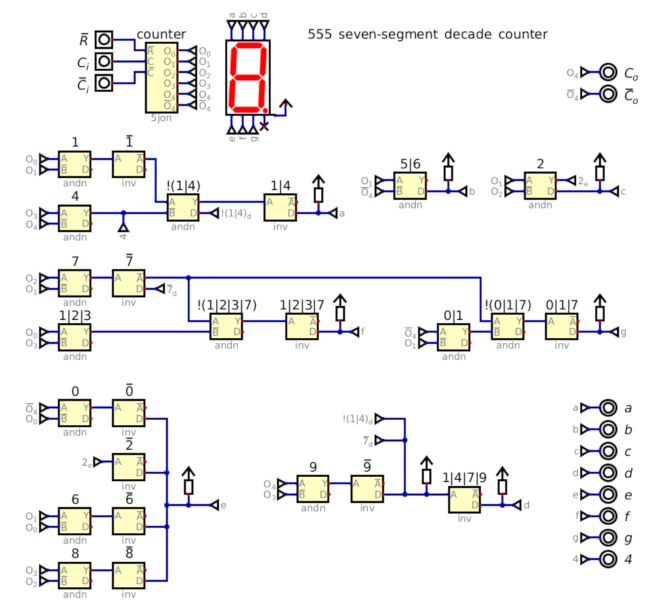
Likely some more optimization can be done, but this is a good start. Note that in addition to a-g outputs, we also have clocks out, and an output for decoded state 4 (this will be used to roll over hours at 24:00). Smaller decoded counters for tens places can be done by simplifying this decade counter.
Discussions
Become a Hackaday.io Member
Create an account to leave a comment. Already have an account? Log In.