Adrian Studer
-
Diffuser
03/04/2022 at 21:48 • 0 commentsStill chaotic and hard to control, but it looks a lot nicer with a piece of styrofoam as diffuser. And it's easier on the eyes 😎
-
Mysteries solved!
12/26/2021 at 05:58 • 0 commentsThat was quick! The mysteries from my previous project log are already solved. 🥳
Pedantic LEDs
A friend of mine remembered reading about an issue with resetting NeoPixels. He sent me a link to this blog post by Particle which resolves that mystery:
https://blog.particle.io/heads-up-ws2812b-neopixels-are-about-to-change/
TL;DR the minimum length of the reset pulse for the WS2812B changed from 50us to 280us.
A short twist on the trim pot of the 555 in charge of the reset pulse and my 16x16 RGB matrix lights up! Good thing the range of this trimmer was extended from 150us to 350us due to parts availability.
555 Reset Behavior
The other head-scratcher was that the 555 timers didn't immediately stop when their reset pin was pulled low. Turns out I ran into another 555 speed limit.
Googling for 555 reset behavior I found lecture notes stating:
"Delay time from reset to output is typically on the order of 0.5 μS, and the minimum reset pulse width is 0.5 μS. Neither of these figures is guaranteed, however, and may vary from one manufacturer to another."
I didn't find any mention of this in the datasheet for the Texas Instruments TLC556 that I use. However it is mentioned briefly in the LM555 datasheet:
"Delay time reset to output is 0.47 μs typical. Minimum reset pulse width must be 0.3 μs, typical."
In my screenshots I eyeball a delay of about 0.4 us, so that checks out.
Interestingly, while covered in the datasheet for the TLC556, the LM555 datasheet doesn't mention the effects of propagation delays on maximum frequency. Go figure!
-
Pedantic LEDs
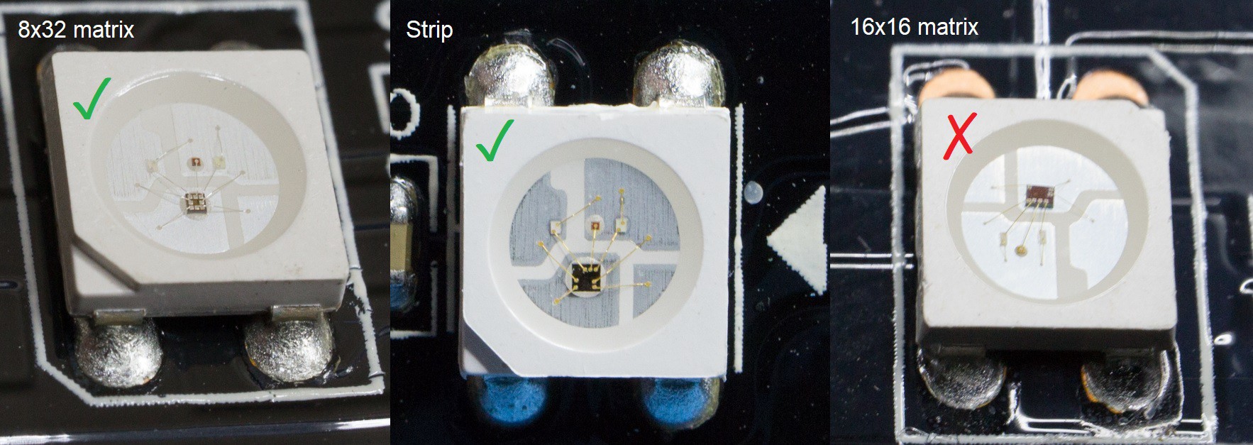
12/26/2021 at 01:10 • 0 commentsAs mentioned in my previous update, I have a 16x16 RGB LED matrix that, unlike the LED strip and the 8x32 matrix, does not light up with the NeoPixel Punk Console.
I used an Arduino and the sample sketch of the Adafruit NeoPixel library to verify that the LED matrix is not defective, and that works as expected. So the issue is definitely caused by something that my circuit does.
NeoPixel is a brand name invented by Adafruit to cover a whole class of RGB LEDs that use the same protocol. The most famous is the WS2812, but there are also WS2812B, SK6812, and likely several more.
And indeed, despite having bought all my RGB LED toys from the same vendor/brand (BTF-Lighting) and being from the same product line (WS2812B ECO), they all use different LEDs!
![]()
While they all speak the same protocol, #3 seems to be more pedantic about following the specifications.
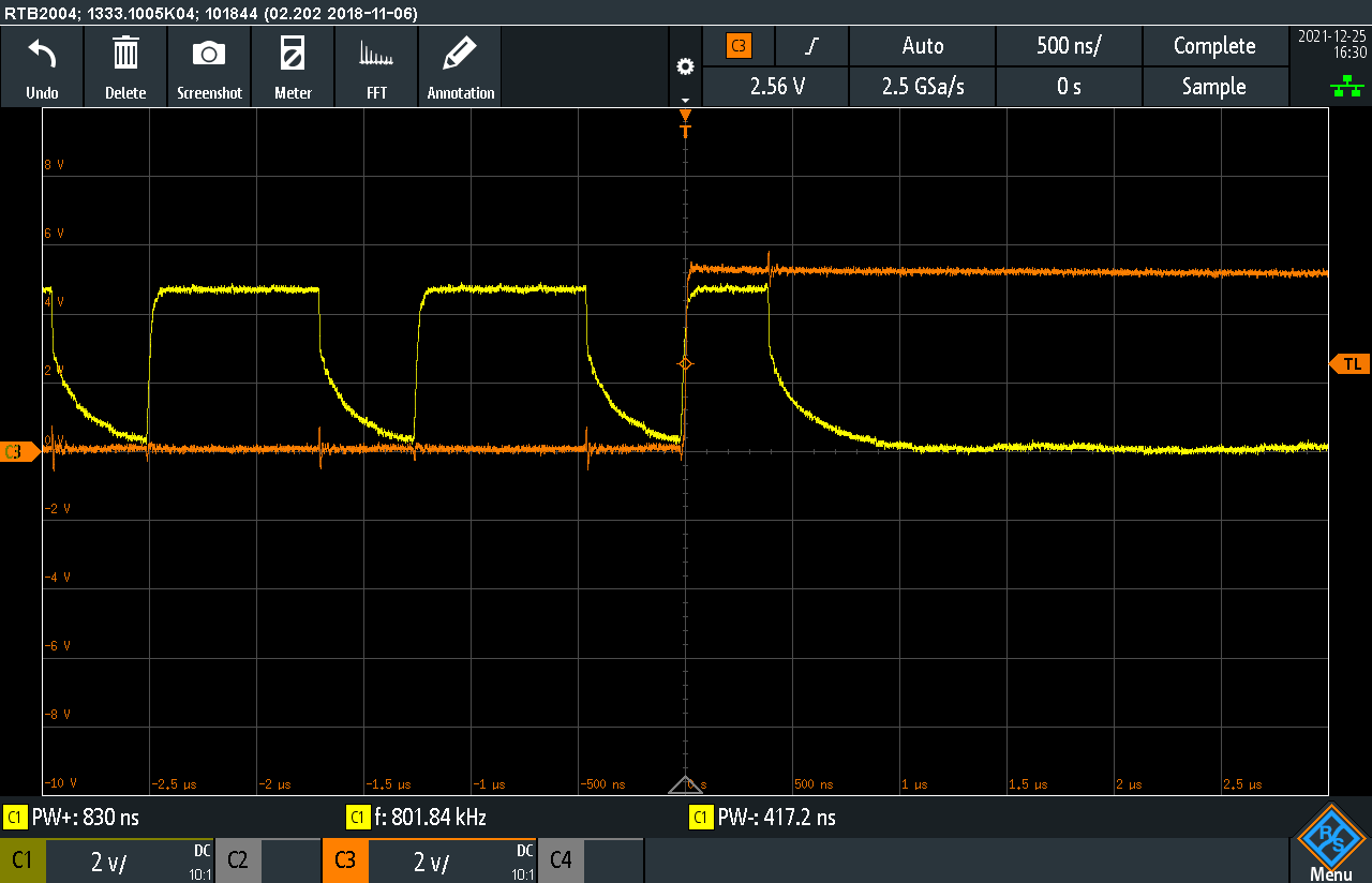
My first thought was about timing or signal quality. But probing the data out pin on a few of the LEDs on the 16x16 matrix shows that the LEDs are recognizing, processing and forwarding 0, 1 and reset pulses as expected. So that doesn't seem to be the issue.
But while probing around, I noticed a glitch that may upset some NeoPixel variants: When the reset pulse is due (orange trace, RST_PULSE in the schematic), the NeoPixel Punk Console still sends out an extra pulse before going low (yellow trace, DATA_OUT in the schematic).
![]()
Side note: The negative edge of DATA_OUT is quite slow due to the diode-logic OR using a pull-down resistor. I tried a lower resistor value which cleaned up the signal but didn't fix the issue with the 16x16 matrix.
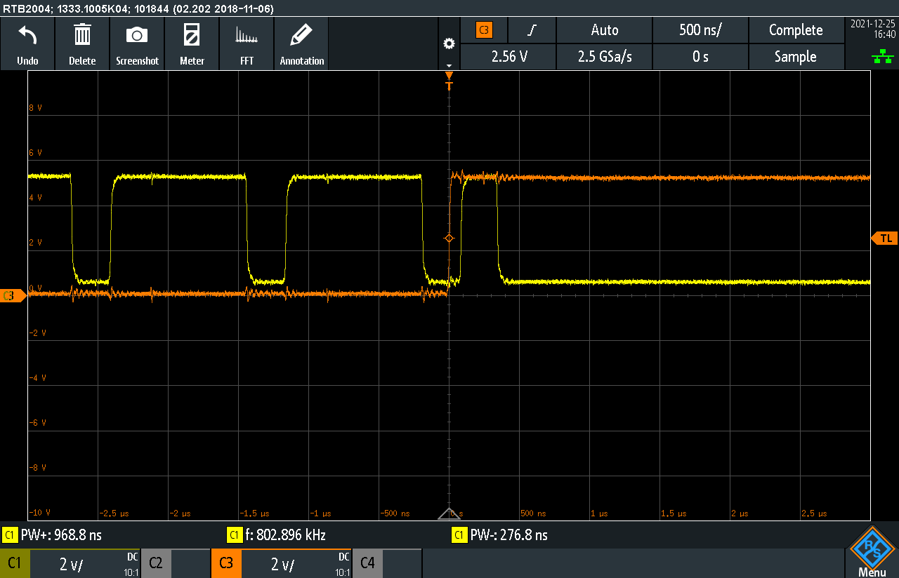
To force DATA_OUT low during reset, the inverted RST_PULSE is connected to the reset input R of the 555 timers generating CLK, LO and HI pulses. I expected this to force their output Q low instantly. But looking at CLK as an example (yellow trace), this is not the case:
![]()
My current working theory is, that the state machine inside the RGB LED used on the 16x16 matrix is interpreting this pulse differently than the others. For example, the LED could zero its "color" register at the start of each new 24-bit packet of pixel data, which in case of an extra 0-pulse like above would result in all LEDs staying dark.
To fix this glitch I plan to directly combine the inverted RST_PULSE with DATA_OUT through an AND gate. Funnily, that's how it's wired in my original sketch, but I tried to be smart and save a gate. 🙄
PS: I'm stumped why the 555 timers still generate a pulse while reset is already low. Any ideas?
PS2: Mysteries solved! See next log.
-
8x32 LED Matrix
12/22/2021 at 23:10 • 0 commentsWorks great with this 8x32 RGB LED matrix!
For some reason a 16x16 matrix from the same vendor doesn't work at all.
Update: The 16x16 matrix also works after tweaking the reset timing. Details here.
-
Speed Limit 555
12/22/2021 at 01:24 • 0 commentsYou may have noticed that the adjustable ranges of the pulse generators just barely meet the requirements of the RGB LED.
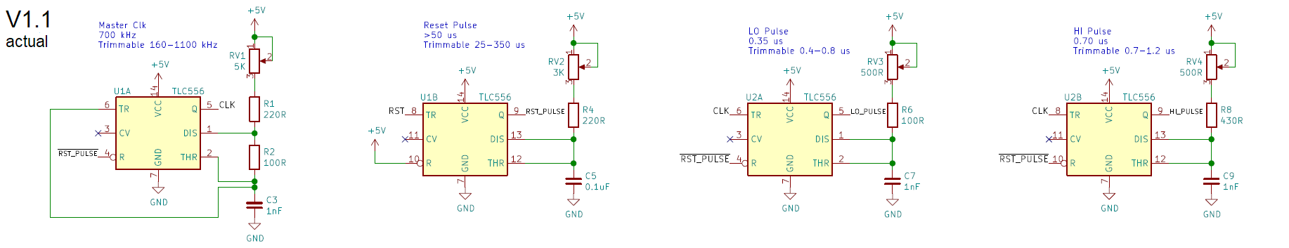
![]() The ranges noted in the schematic v1.1 were measured with an oscilloscope on the assembled circuit. They are quite different from what I noted on my original schematic v1.0:
The ranges noted in the schematic v1.1 were measured with an oscilloscope on the assembled circuit. They are quite different from what I noted on my original schematic v1.0:![]()
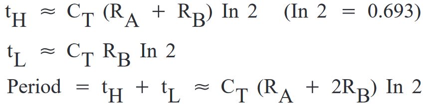
For the original design I picked resistors and capacitors to get ranges with my requirements sitting comfortably within. The range was calculated based on the formula found in the datasheet.
![]()
Ok, I cheated and used an online calculator.
It worked well for the reset generator, which ranges down to 25 us, equivalent to 40 kHz (the upper end changed because the 1K potentiometer was replaced with 3K due to component availability). But the lower end of the LO and HI pulse, as well as the top frequency of the master clock circuits were way off. Even after lowering the resistor values the circuit only barely meets the requirements.
The datasheet of the Texas Instruments TLC556 specifies the maximum frequency as 1.2-2.1 MHz. We're getting close to that, but still seem to be within the specs.
![]()
Note that the datasheet gives us component values used to measure the maximum frequency. If we plug those into the 555 formula, we get a maximum frequency of 8.3 MHz and pulse widths of 0.03-0.1 us. That's way faster than the specified 1.2-2.1 MHz!
Well, turns out that the formula is an approximation assuming an ideal 555.
My first thought was parasitic capacitances in the 555 and my circuit. Adding 1 nF to Ct gets us closer to the theoretical values, but that seems a bit high for a CMOS chip on a printed circuit board.
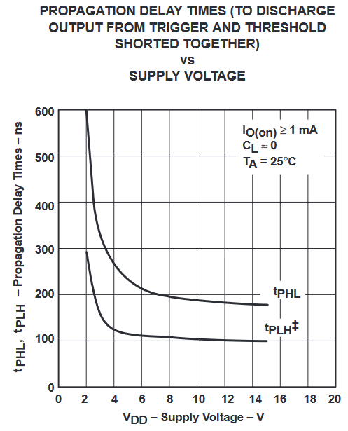
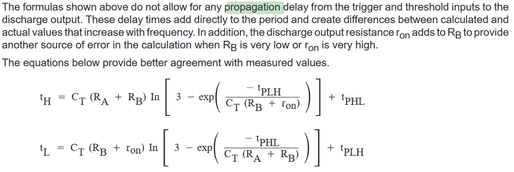
A more relevant factor seems to be the propagation delay of the comparators in the 555. The TLC556 datasheet specifies propagation delay with this chart:
![]()
At 5V, the chart indicates 120-250 ns delay from triggering to actual discharge, which is significant if our goal are 300-700 ns pulses!
And lo and behold, searching the datasheet for propagation delay reminds me that I should read chapters from end-to-finish, not just run with the first formula! 🤦
![]()
Ah well.. my NeoPixels light up, so I won't dwell on this any further. ¯\_(ツ)_/¯
PS: The v1.0 schematic also used AC coupling for the triggers. The RC elements of this circuit created a low-pass filter that was way too slow for my requirements. I had some success by replacing the 1 uF capacitor with 1 nF, but in the end it was easier to simply connect the triggers directly to their source signal.
-
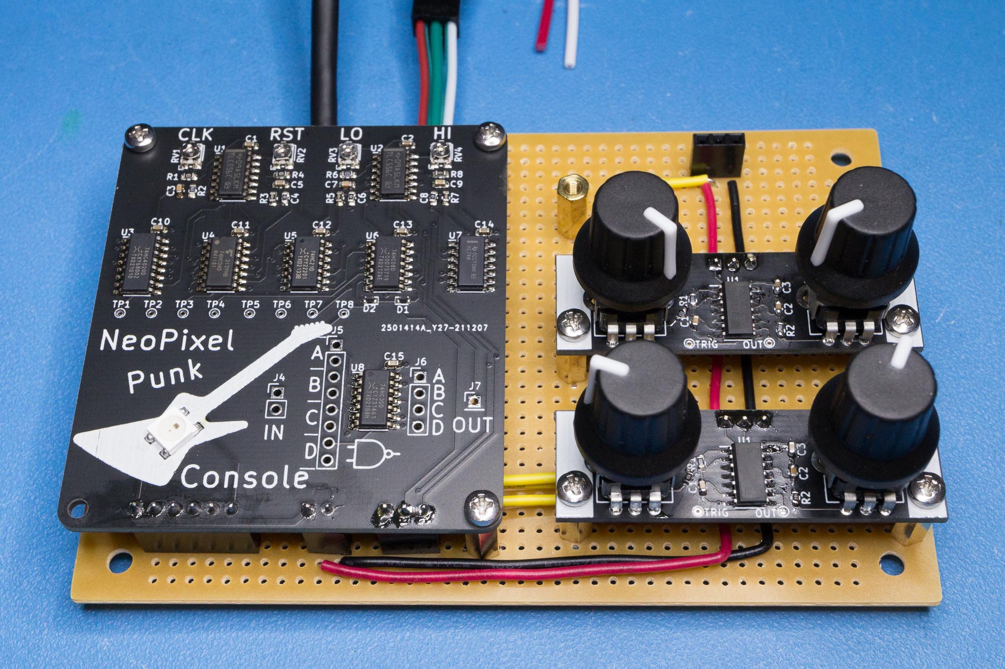
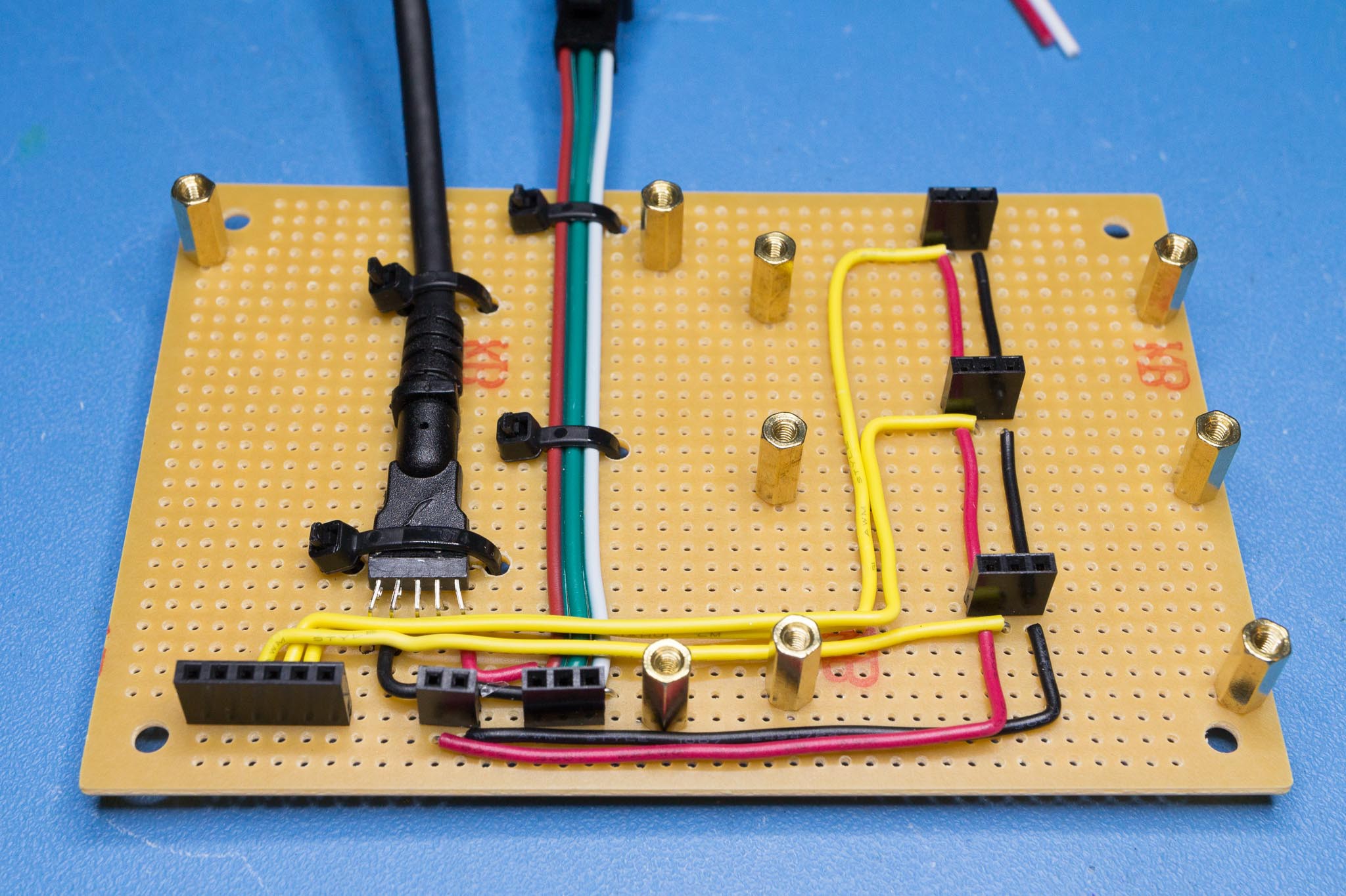
From Breadboard to Perfboard
12/21/2021 at 05:54 • 0 commentsI migrated from a tangle of jumper wires and breadboards to a more permanent setup.
![]() The red-green-white cable is a pigtail that came with the LED strip. The connector at its end seems to be semi-standard used by various RGB LED strips and matrices. The thick black cable is a USB cable salvaged from a cheap USB 3 hub. The business end of that cable is a USB A plug used to supply 5V power from a battery or phone charger.
The red-green-white cable is a pigtail that came with the LED strip. The connector at its end seems to be semi-standard used by various RGB LED strips and matrices. The thick black cable is a USB cable salvaged from a cheap USB 3 hub. The business end of that cable is a USB A plug used to supply 5V power from a battery or phone charger.
And here how it looks with everything plugged in. The second color oscillator board is still missing.![]()
I should clean up those solder joints with a bit of IPA. 🙄 -
Touchy-Feely
12/19/2021 at 05:36 • 0 commentsThe NeoPixel Punk Console turned out to be a very sensitive apparatus.
If you let it just sit with a cool effect dialed in, within a few minutes the LEDs will slowly drift back into flashing chaos. I suspect that some of the low-value resistors are heating up, and being sourced from a Chinese 5% SMD assortment their temperature coefficients are probably terrible, which will ruin any harmony.
There are also configurations where the LEDs behave somewhat.. hesitant?
My theory is, that as some LEDs wander on and off the strip the current draw changes, which makes the supply voltage raise or drop, which influences the oscillator timings. -
It's alive!
12/18/2021 at 05:37 • 0 commentsHere are a few videos of the current state of this project.
First light with just the pixel oscillator. The LEDs are mostly white, but look blue in this video due to white balance and the blue backing tape of the strip.
In the second video I added one color oscillator, and got very lucky with knob twiddling resulting in an effect close to what I hoped for.
Unfortunately, getting something else than frantic flashing is quite finicky. Below a few minutes of me trying unsuccessfully to reproduce the above effect. The annoying sound is a speaker hooked up to the output of the pixel oscillator.
I will have to explore different approaches for generating the bit stream.
NeoPixel Punk Console
Blinking RGB LEDs with 555s and a handful of 74-series logic
 The ranges noted in the schematic v1.1 were measured with an oscilloscope on the assembled circuit. They are quite different from what I noted on my original schematic v1.0:
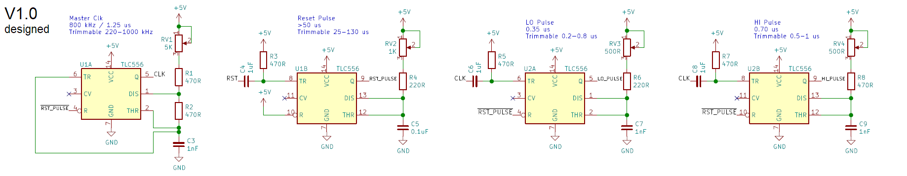

 The red-green-white cable is a pigtail that came with the LED strip. The connector at its end seems to be semi-standard used by various RGB LED strips and matrices. The thick black cable is a USB cable salvaged from a cheap USB 3 hub. The business end of that cable is a USB A plug used to supply 5V power from a battery or phone charger.