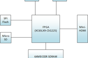
This project uses a PCB board with a NodeMCU ESP8266, coded to control 216 NeoPixels, that animates the side of a computer tower with the famous "raining code" animation from the Matrix franchise.
The NeoPixel control board is a modular, customizable PCB breakout board for controlling multiple strips of NeoPixels with user input options to control the speed and brightness of the display with potentiometers and control the animation mode with a push button.
This project does use tools like laser cutters that are not accessible to everyone, so alternative options and suggestions throughout this project such as creating a spray paint stencil with a traditional printer and also building a breadboard circuit instead of having the PCB boards fabricated via online services.
Computer with a power supply that has one 5V and GND pin available. Alternatively can bypass the inbuilt power supply and power the circuit by a traditional 5V 5Amp power supply
Tools
Laser cutter (optional but recommended)
Soldering iron
Allen key for M3 bolt
Miscellaneous tools: Wire strippers, snips
2
PCB Fabrication
I designed this PCB in Fusion 360 electrical, in the next section you can see the electronic schematic. To fabricate the board I sent the Gerber files to PCBWay at www.pcbway.com (Disclaimer: the YouTube video I posted of this build process is sponsored by PCBWay).
Download the latest Gerber files zip version from the GitHub repo. As of publishing (Dec 12 2021), the latest version is v1-2-0. This zip file can be uploaded directly to the PCB fabrication website with the default options left as is. https://github.com/WillDonaldson/NeoPixel_Control_Board/tree/main/gerber-files
When assembling the PCB you will notice in the pictures above I have marked the PCB with all the labels of where the different resistors, diodes, chips, and other components go.
Alternatively, if you do not want to have this board fabricated you can assemble the circuit on a breadboard, following the wiring schematic in the next section.
3
Circuit Assembly
As mentioned in the previous section, the first picture in this section shows the electronic schematic. This can be used as a reference when assembling the circuit, although I did my best to label all the components directly on the PCB so you can follow the markings directly on the board when assembling the circuit.
Alternatively, you can also assemble the circuit on a breadboard. I have a picture showing this although I opted to use an Arduino Nano for this whereas the PCB uses an ESP8266, you are free to use any microcontroller, you'll just need to update the pin assignments in the code accordingly.
soooo cool!