Close
0%
0%

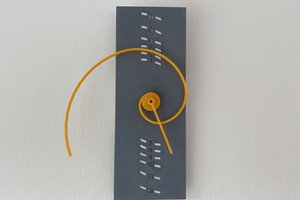
Belgian Railway Station Clock

A 3D printed, double sided view, Belgian Railway Station Clock, synchronized with the network time.

Similar projects worth following
This project describes the making of a 'Belgian Railway Station Clock'. The clock is connected to the netwerk via WiFi. In this way, the clock is controlled by the exact (local) time. The clock can be viewed from both sides. The major part of the components are 3D printed.

The working of the clock is in the same way as the mechanism of the Belgian railway station clock. This means, the seconds hand starts his cycle at the beginning of a new minute. It takes about 57 seconds to make one rotation. The seconds hand terminates his orbit at the highest marker indicator. Standing there, he has to wait untill the new minute begins. At the same moment, the minutes hand makes a jump to the new corresponding minute marker.

Although the clock is designed for double-sided view, the clock can be made for only a single sided view. In this way, the number of components and the number of parts to be 3D printed will be reduced.

For printing the 3D parts, you can open the SketchUp file in annex and you can make the corresponding STL-file.

It's also possible to illuminate the clockface. For more information, follow the instructions.

The program in the Arduino makes the clock work like a real Belgian station clock. However, if you take a look at the station clock in e.g. the Netherlands or in Germany, the working of the clock is almost in the same way. Hereby, I want to say, that the movement of the seconds hand can be different. I saw that in Germany, the seconds hand moves with a 'tick'. Otherwise, in the Netherlands, the seconds hands moves from one mark to the next mark with a small moving jump. If you wish, with some research, you can adapt the source code of the Arduino, so that the clock works like a real station clock in other countries.

Enjoy your station clock and have fun making this nice thing.

BelgianStationClock_NTPClient_login_password_hided.ino

ESP8266 (ESP-01) sketch for the WiFi connection to the network.

ino - 1.15 kB - 12/19/2021 at 16:13

Download

BelgianStationClock.ino

Arduino Nano sketch for clock driver.

ino - 6.70 kB - 12/19/2021 at 16:13

Download

BelgianStationClock.skp

SketchUp (2016) drawing file.

SSEYO Koan Play File - 6.35 MB - 12/19/2021 at 16:13

Download

  • 2 × Arduino Nano Controller for the clock (only 1 required for a single sided clock).
  • 1 × ESP-01(S) ESP8266 WiFi module to make the connection to the network.
  • 6 × IR tacho sensor IR optocoupler to detect the positions of the clock hands (only 3 required for a single sided clock).
  • 6 × 28BYJ-48 5V + driver board Stepper motor 28BYJ-48 5V + ULN2003 driver board (only 3 required for a single sided clock).
  • 1 × PVC pipe 25cm PVC pipe with an outer diameter of 25 cm, inner diameter of 24 cm, and a length of 10 cm (the length can be shortened to 8 cm for a single sided clock).

View all 13 components

  • 1
    Body of the Clock

    Take a PVC pipe with an outer diameter of 25 cm (inner diameter of 24 cm) and saw off a piece of 10cm.

    In the center of the frame, drill a hole to make the suspension of the clock. The size depends on the diameter of the bolt you want to use. In my case I used a M5 bolt.

    A second hole, to bring in the power cable, could already be drilled. The location of this hole is also in the middle of the pipe, at a distance of approximately 5cm of the previous hole. The diameter depends on the diameter of the cable.

  • 2
    Assemble the clock mechanism

    Start 3D printing the frame of the clock mechanism. You always need to print two of the frame parts. If you want to build a single sided clock, you only need to print one detector and one holder.

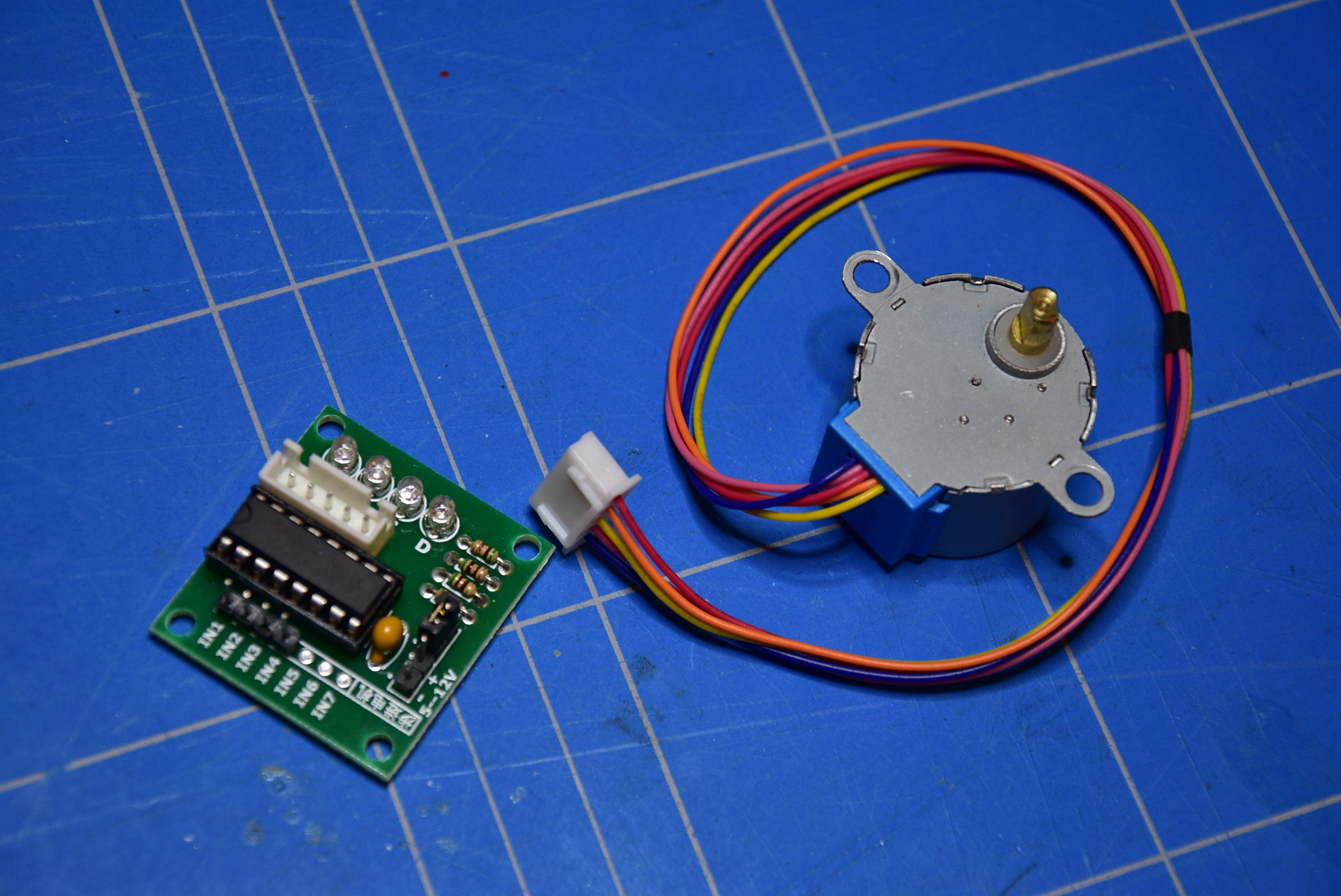
    Take the 28BYJ-48 5V stepper motors with the UNL2003 driver board and cut off/desolder all the connectors, LED's and resistors from the PCB.

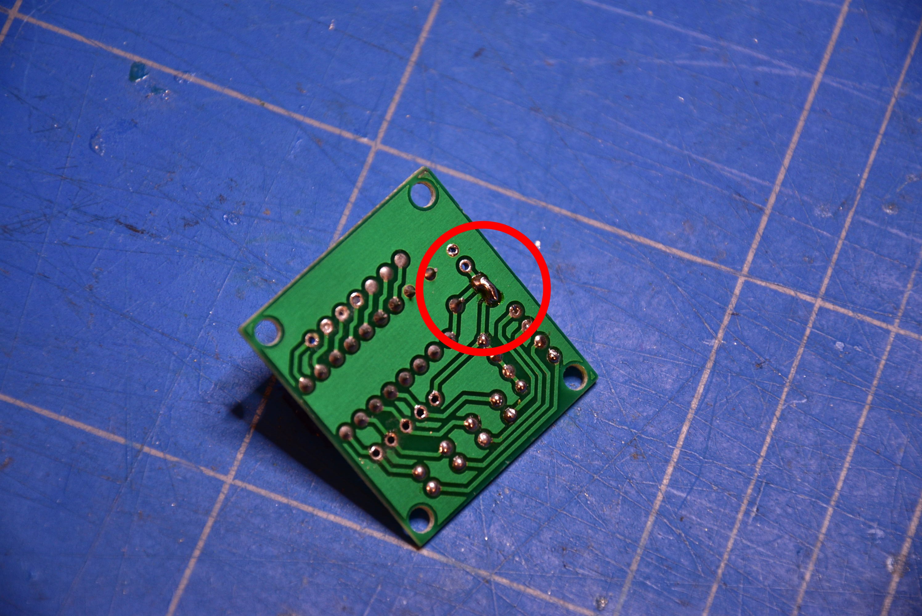
    On the bottom side of the PCB, solder a bridge to make a connection.

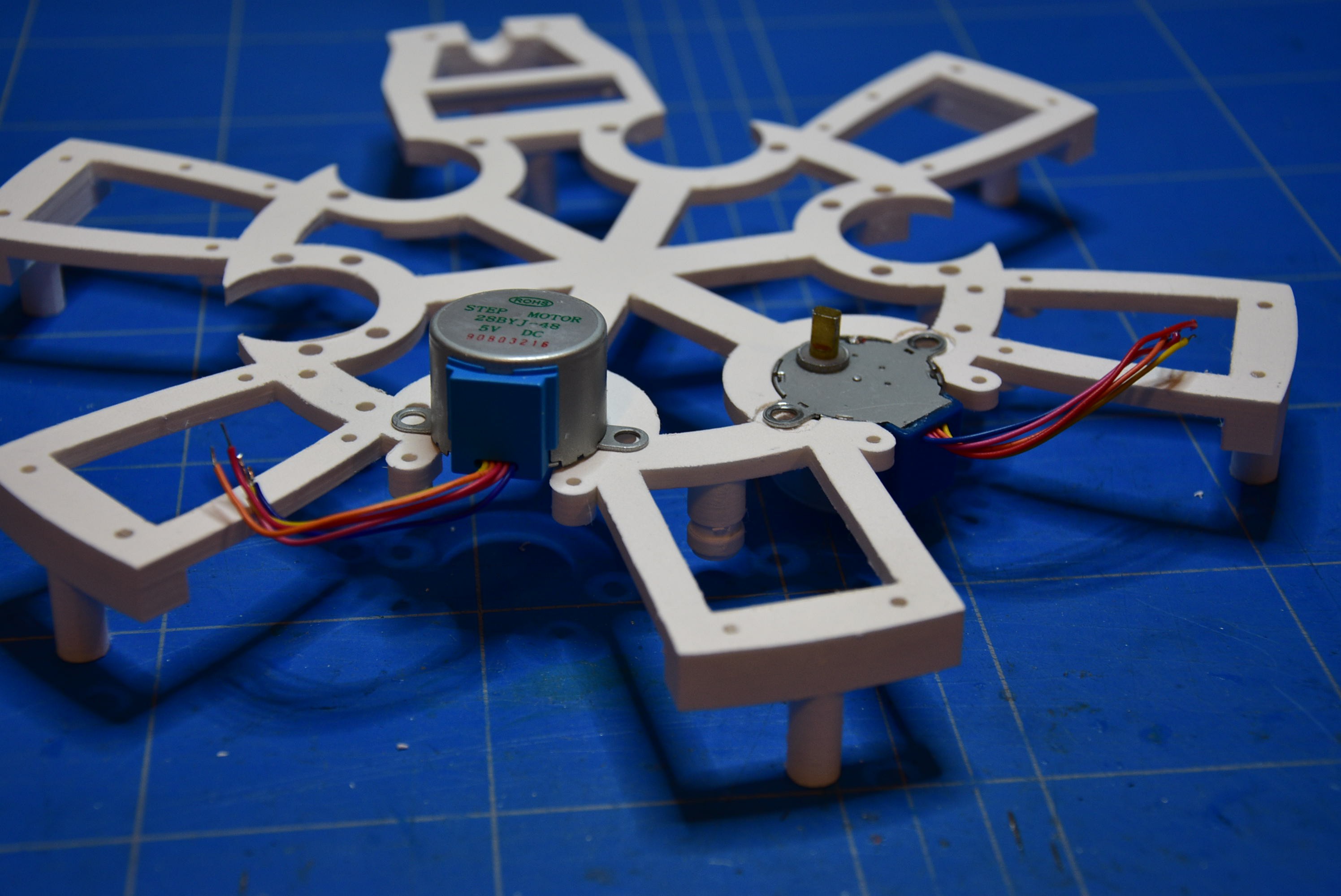
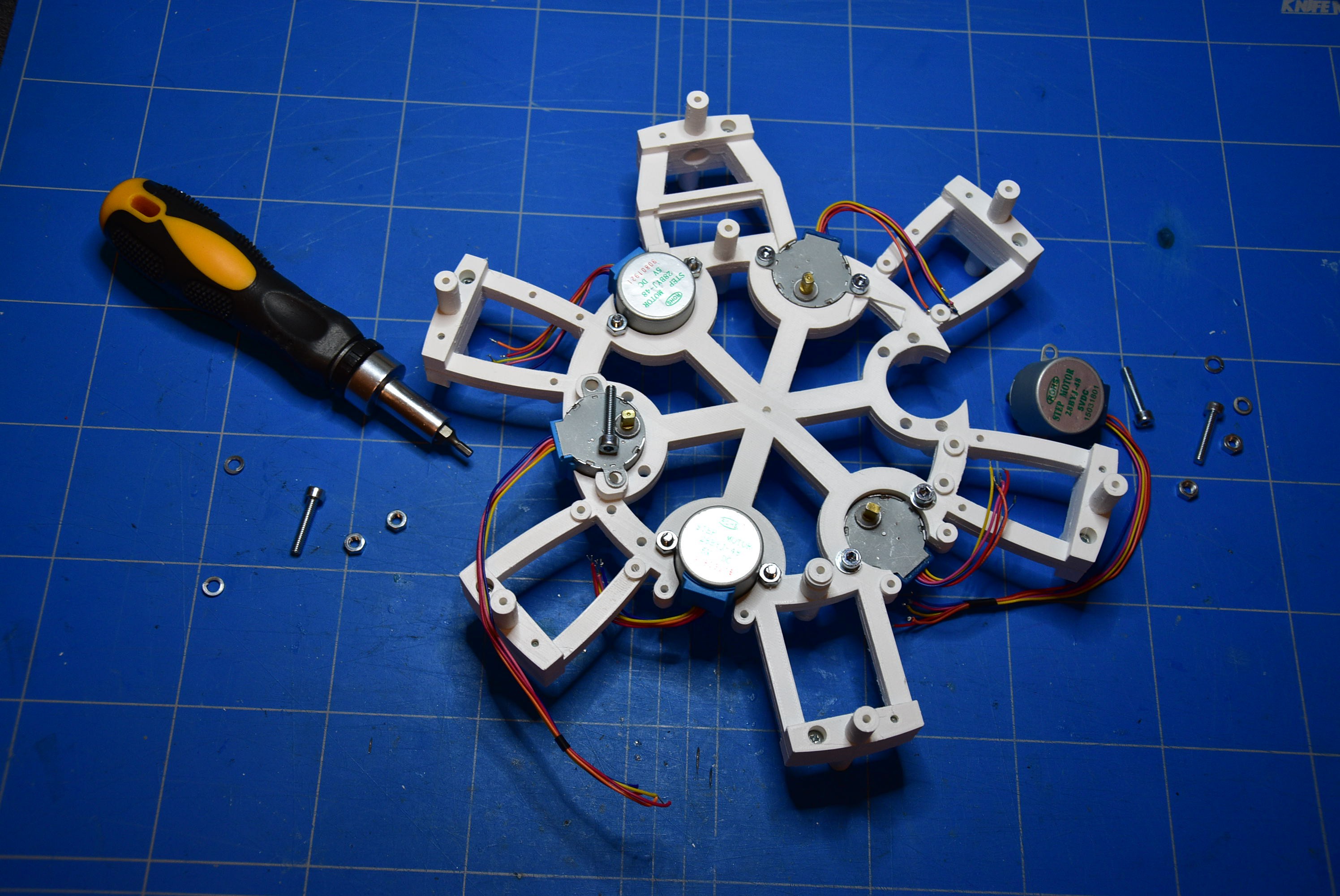
    As shown on the image below, lay down the motor (for the seconds) on one piece of the frame. You only need one stepper motor if you want to bild a single sided clock.

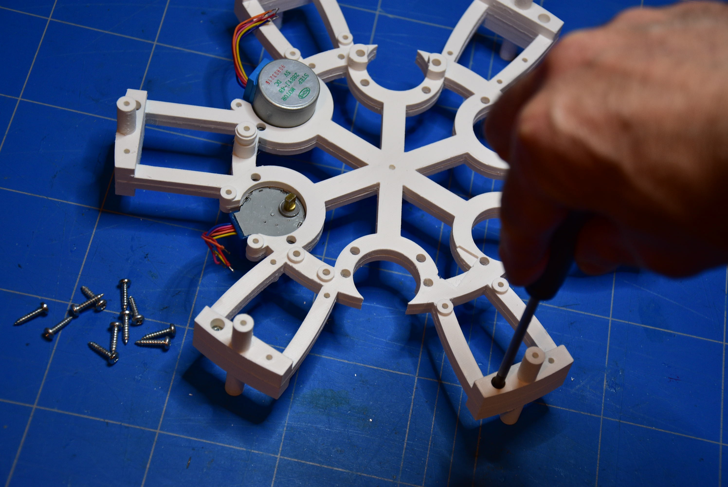
    Cover this with the other part of the frame and fix them together with the screws (2,9mm x 13mm).

    Assemble all the other stepper motors to the frame and fix them with the bolts (M4 x 20mm/25mm).

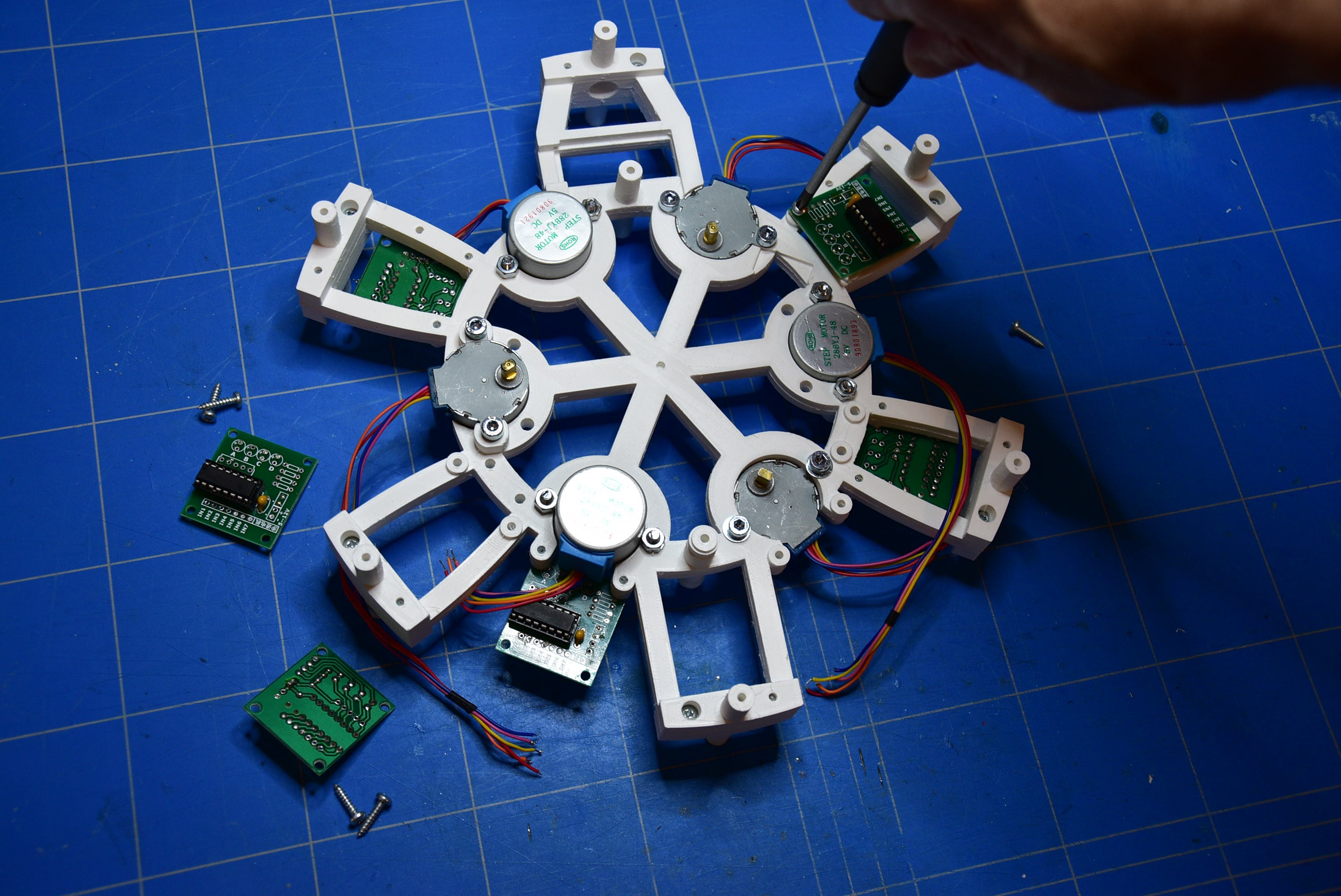
    Fasten the ULN2003 PCB's with the screws (2,9mm x 13mm) to the frame in the correct positions.

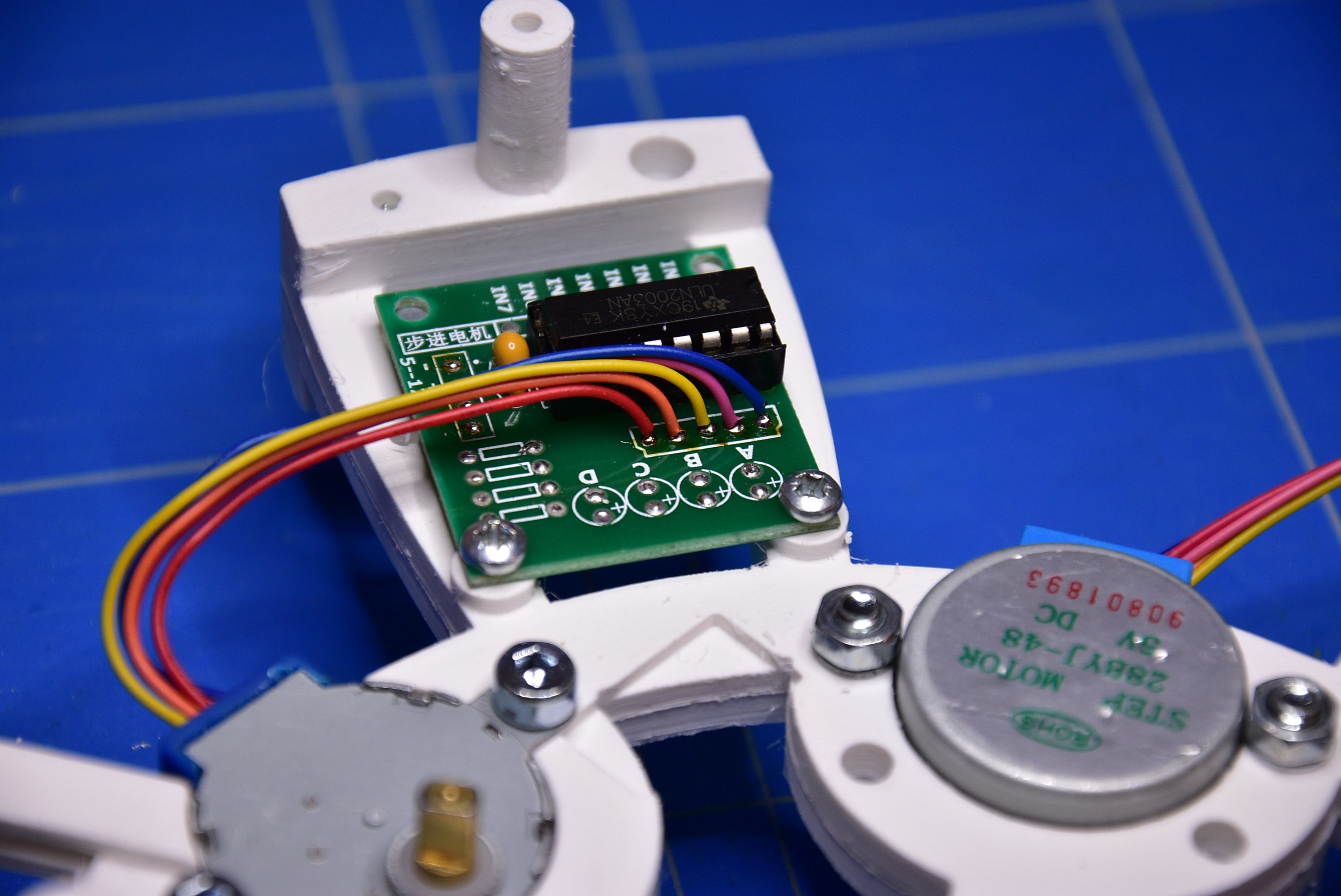
    Solder the wires of the steppers to the PCB's.

    I've noticed that for some stepper motors the colors of the wires are ordered in another way. So, to solder the wires on the PCB's keep the same sequence as the color positions of the connector that was cut off before.

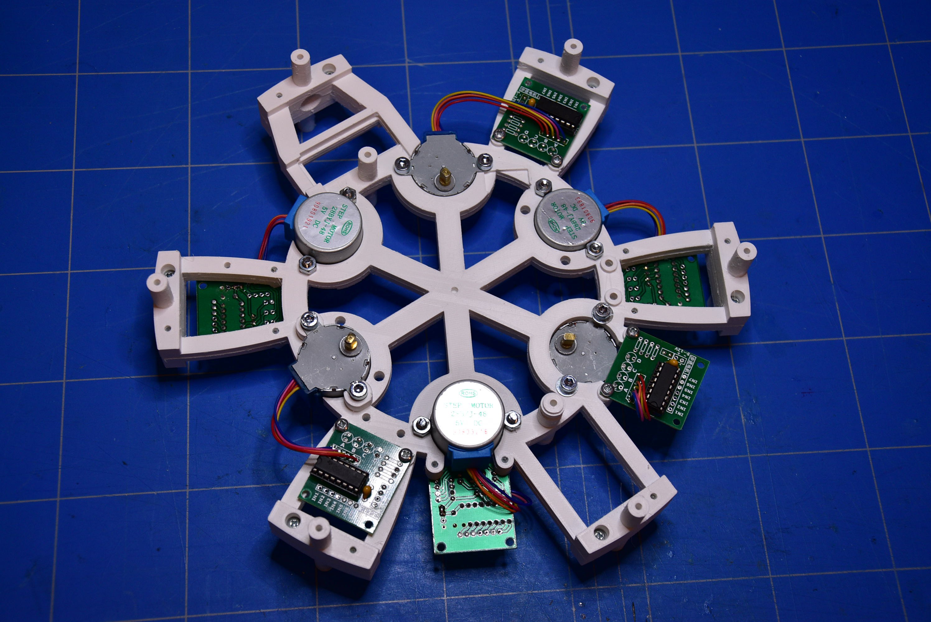
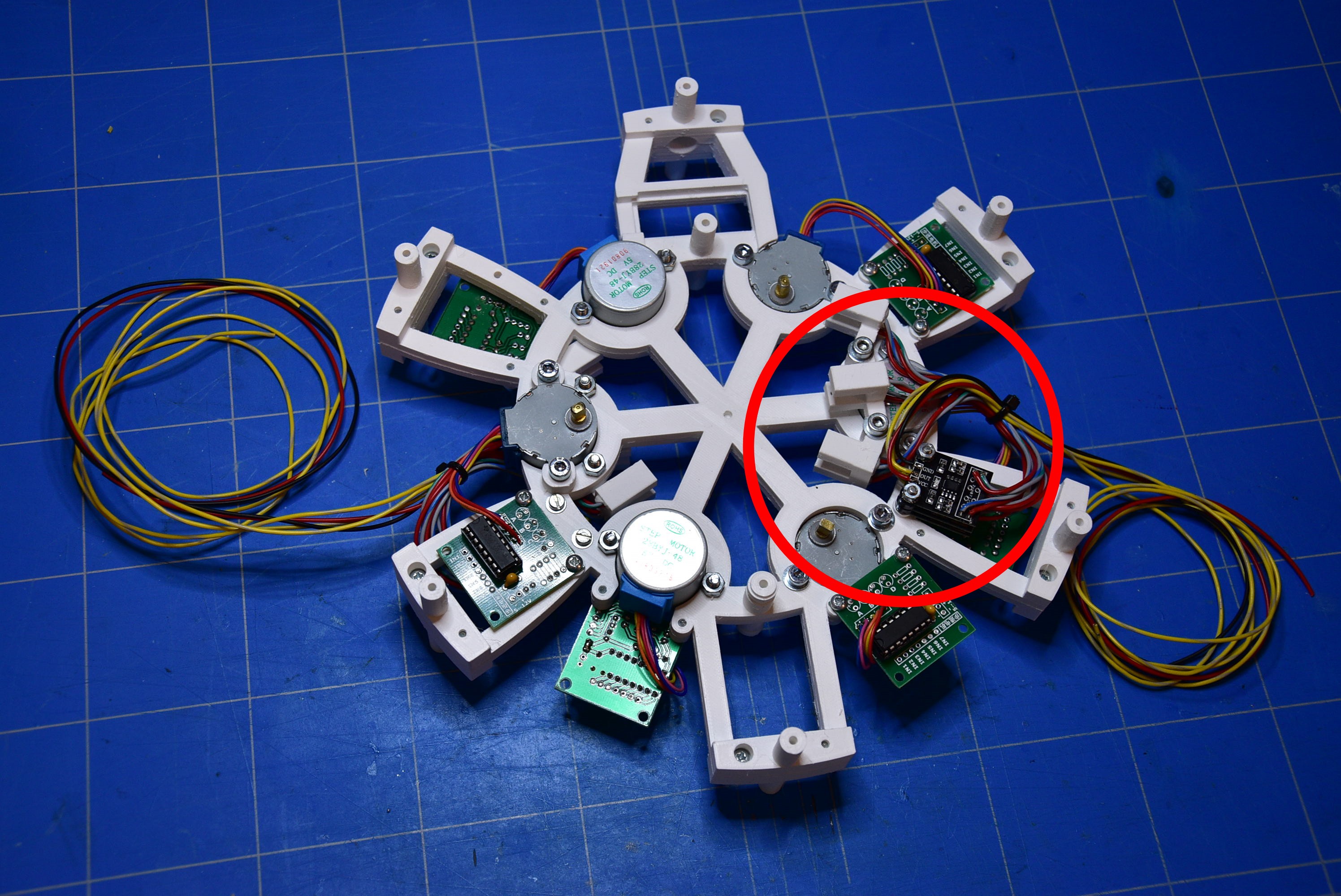
    When al this work is finished, you must have an assembly that looks like the image below.

  • 3
    Clock hand position detectors

    The detection of the position of the clock hands is made by IR detectors.

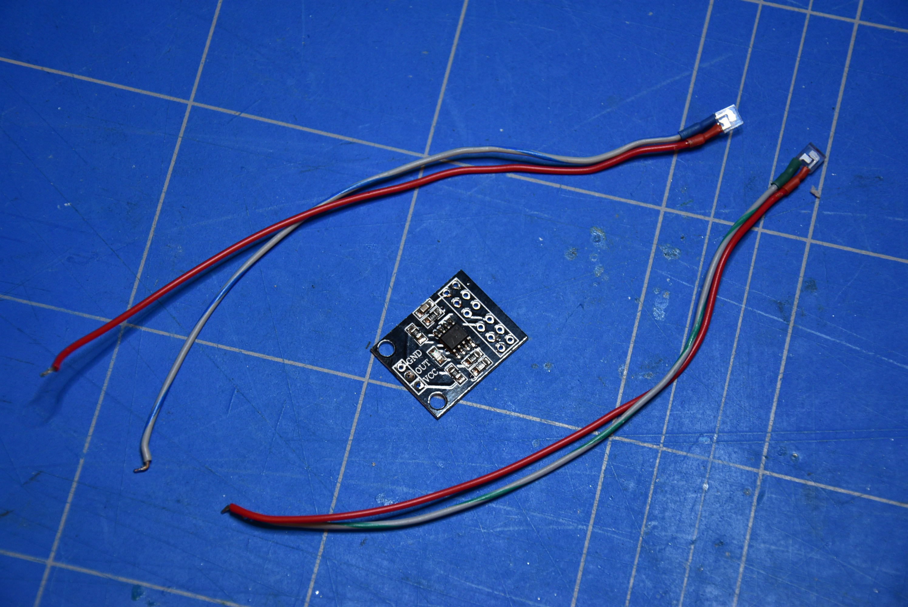
    Take off the hood from the IR detector. Desolder the IR transmitter and the IR receiver, but make a note or set a mark on the components to known how the connection was before ! Solder an extension wire to the pins of the IR transmitter and the IR receiver. Use colored wires so that you can't go wrong and that mistakes are excluded.

    Insert the IR transmitter and the IR receiver into the 3D printed detector frame. Close the gap with some putty.

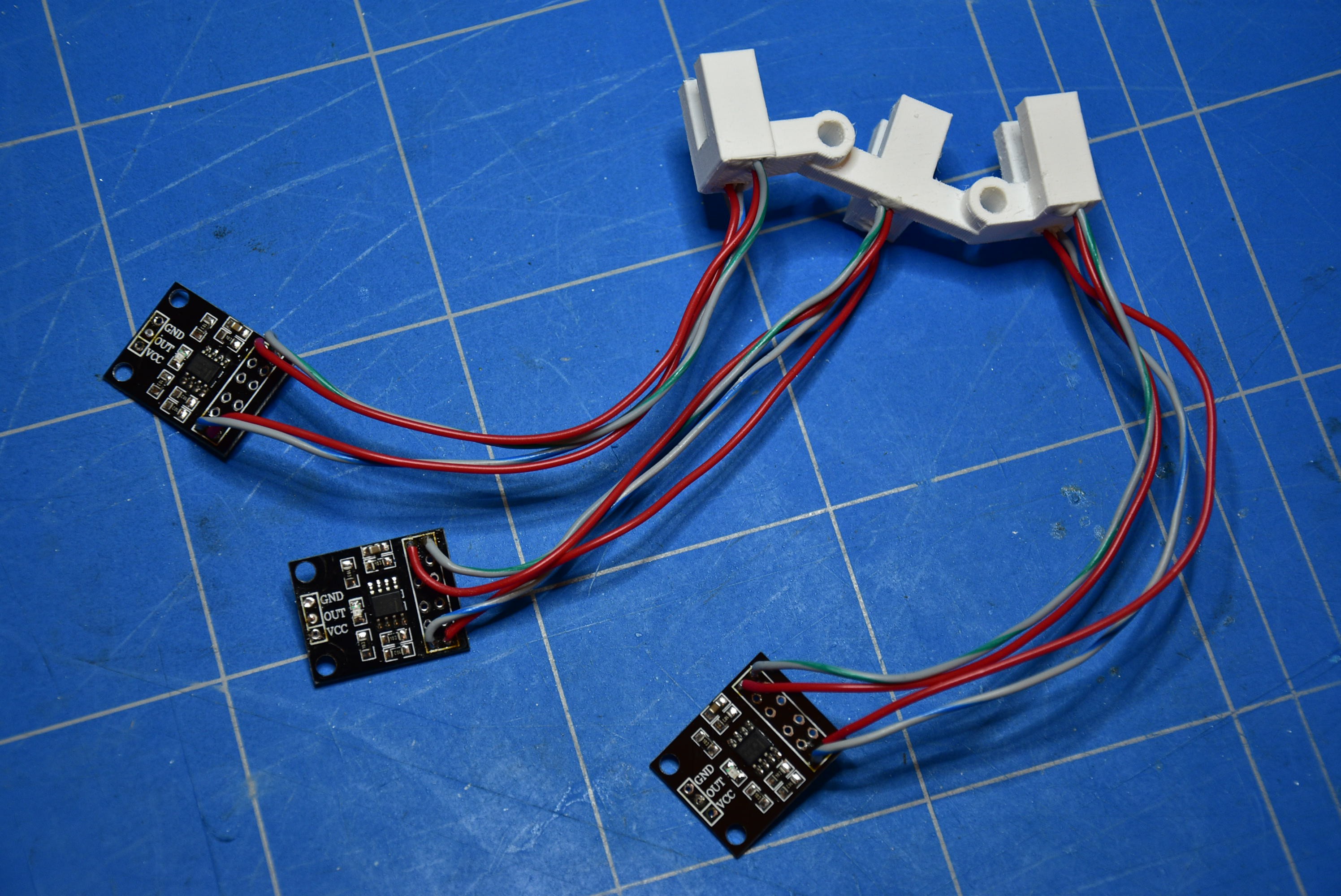
    After preparing the three detectors, you should get an assembly like this.

    Put the three detectors together with a M3 bolt (M3 x 30mm) and some spacers. For each channel, on the 'OUT' pin, connect a wire of about 30cm long. Solder a strap through the PCB so that the 'GND' pins and 'VCC' pins are connected together.

    Attach the detector assembly to the frame. Also solder a black and red wire to the 'GND' and 'VCC' pins, with a length of 30cm.

    Finally, the construction should look like this.

View all 9 instructions

Enjoy this project?

Share

Discussions

radiusmike wrote 12/28/2021 at 00:03 point

Very cool project.  Love it

  Are you sure? yes | no

Similar Projects

Does this project spark your interest?

Become a member to follow this project and never miss any updates