 EBP Controller
-
1Body of the Clock
Take a PVC pipe with an outer diameter of 25 cm (inner diameter of 24 cm) and saw off a piece of 10cm.
In the center of the frame, drill a hole to make the suspension of the clock. The size depends on the diameter of the bolt you want to use. In my case I used a M5 bolt.
A second hole, to bring in the power cable, could already be drilled. The location of this hole is also in the middle of the pipe, at a distance of approximately 5cm of the previous hole. The diameter depends on the diameter of the cable.
![]()
-
2Assemble the clock mechanism
Start 3D printing the frame of the clock mechanism. You always need to print two of the frame parts. If you want to build a single sided clock, you only need to print one detector and one holder.
![]()
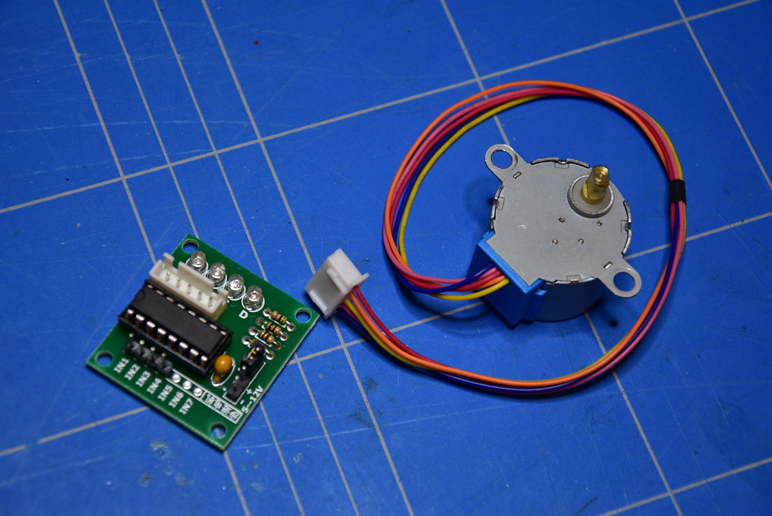
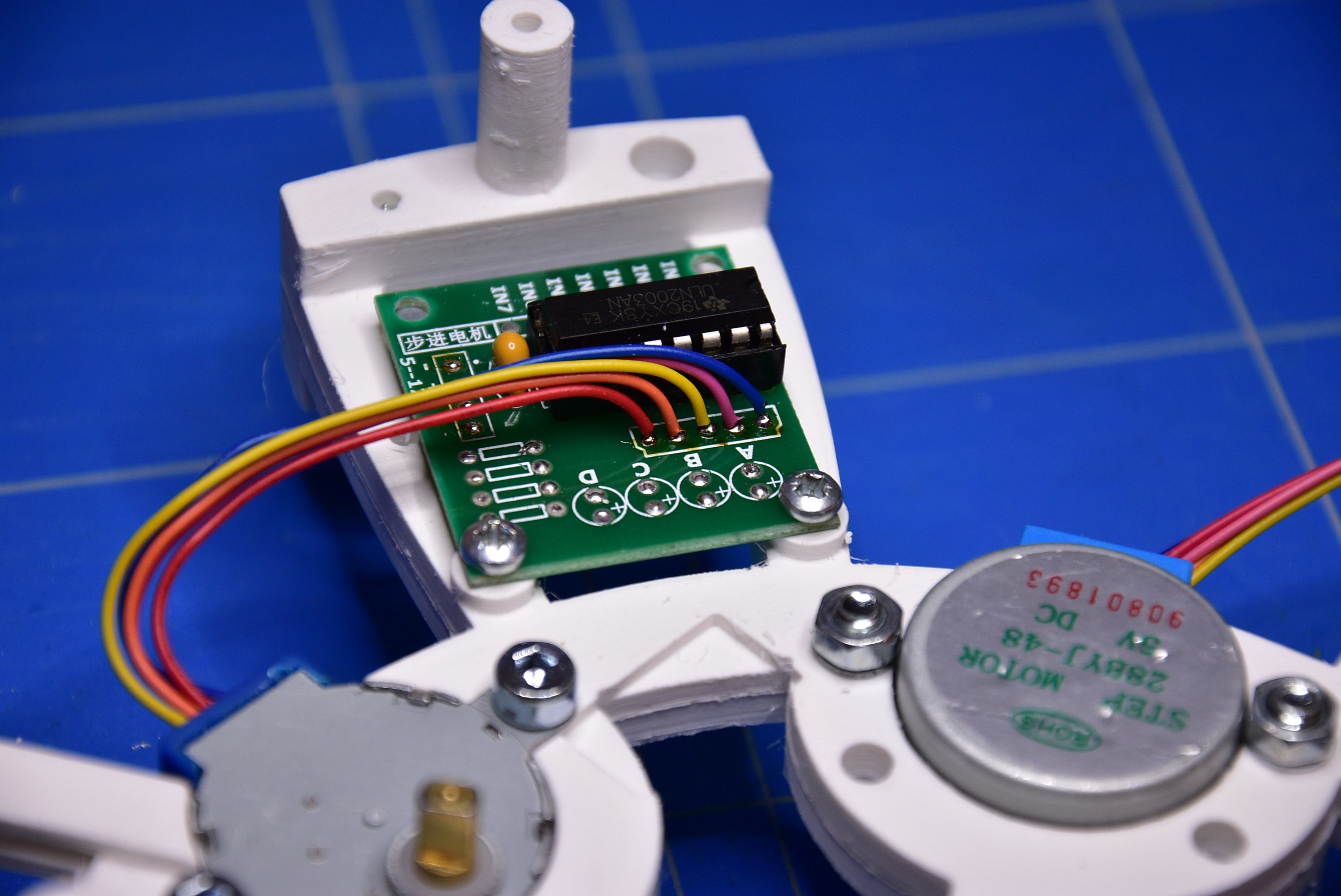
Take the 28BYJ-48 5V stepper motors with the UNL2003 driver board and cut off/desolder all the connectors, LED's and resistors from the PCB.
![]()
![]()
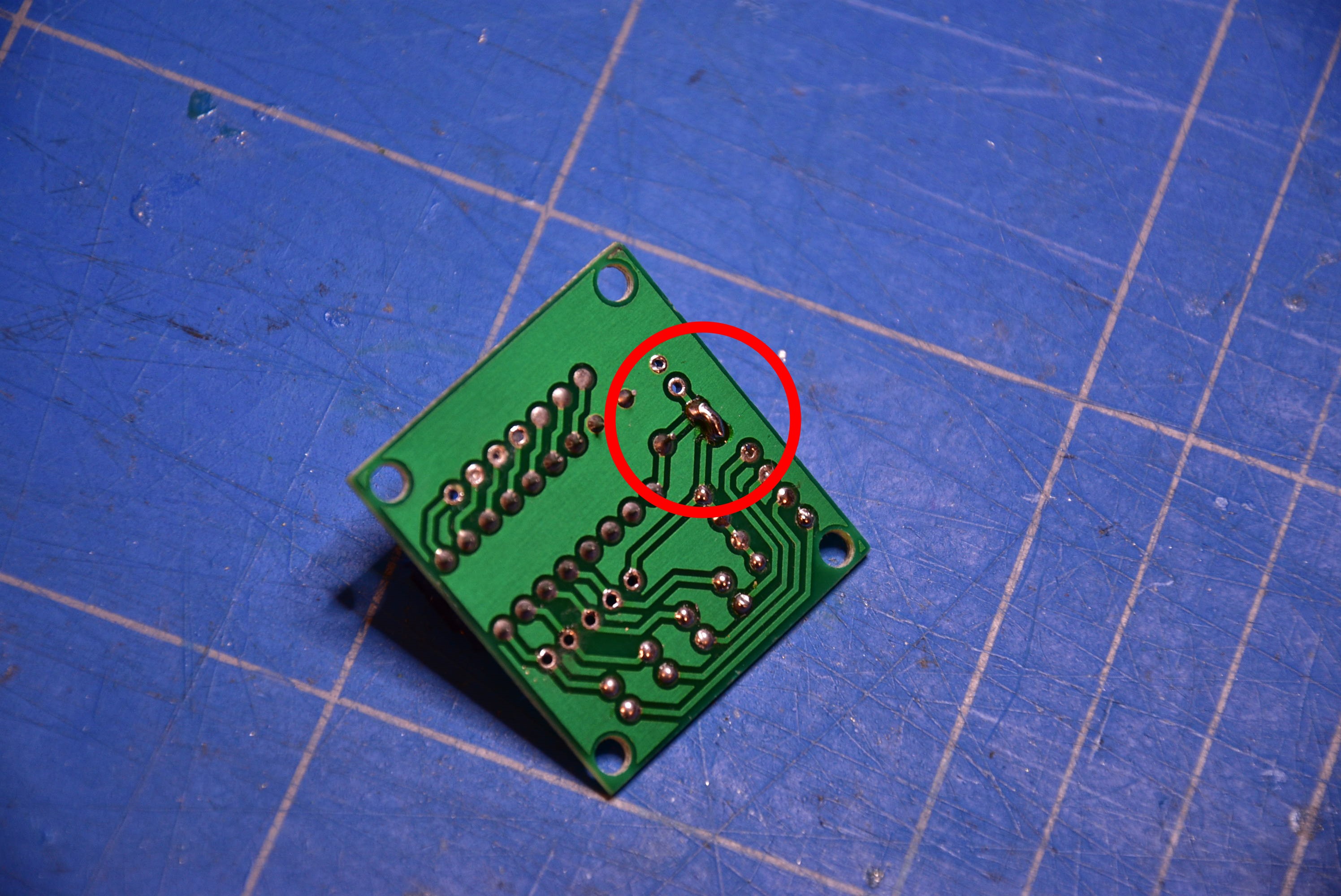
On the bottom side of the PCB, solder a bridge to make a connection.
![]()
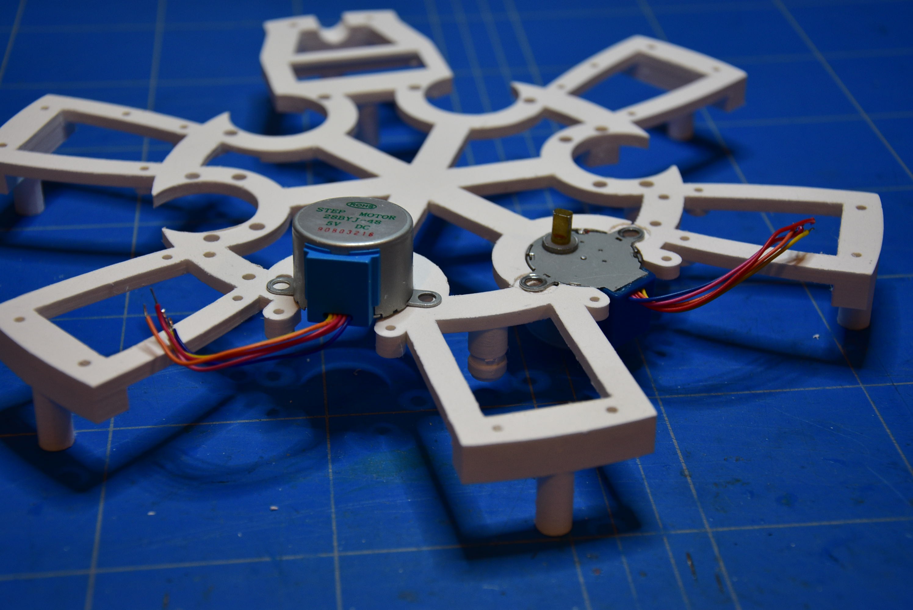
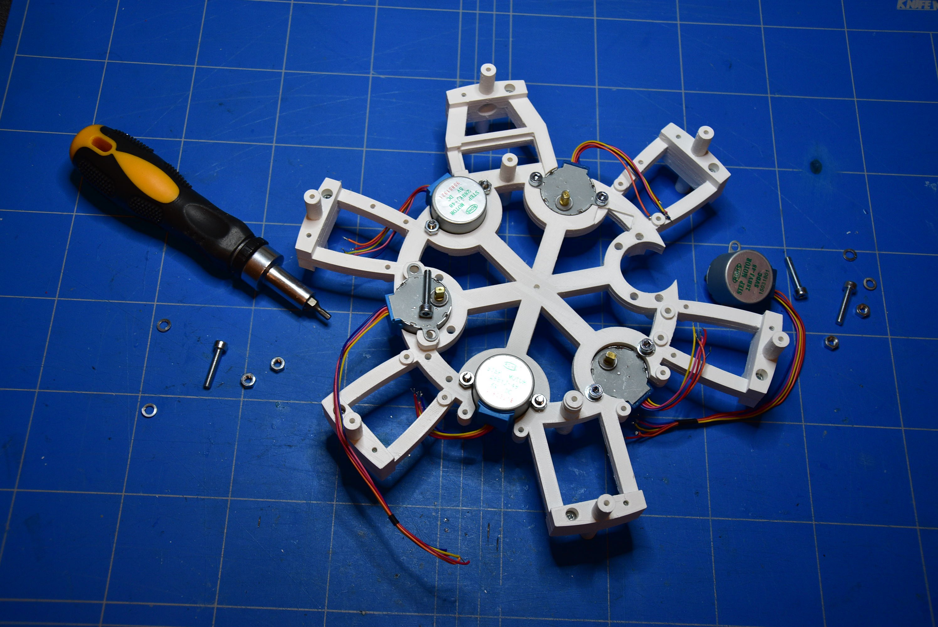
As shown on the image below, lay down the motor (for the seconds) on one piece of the frame. You only need one stepper motor if you want to bild a single sided clock.
![]()
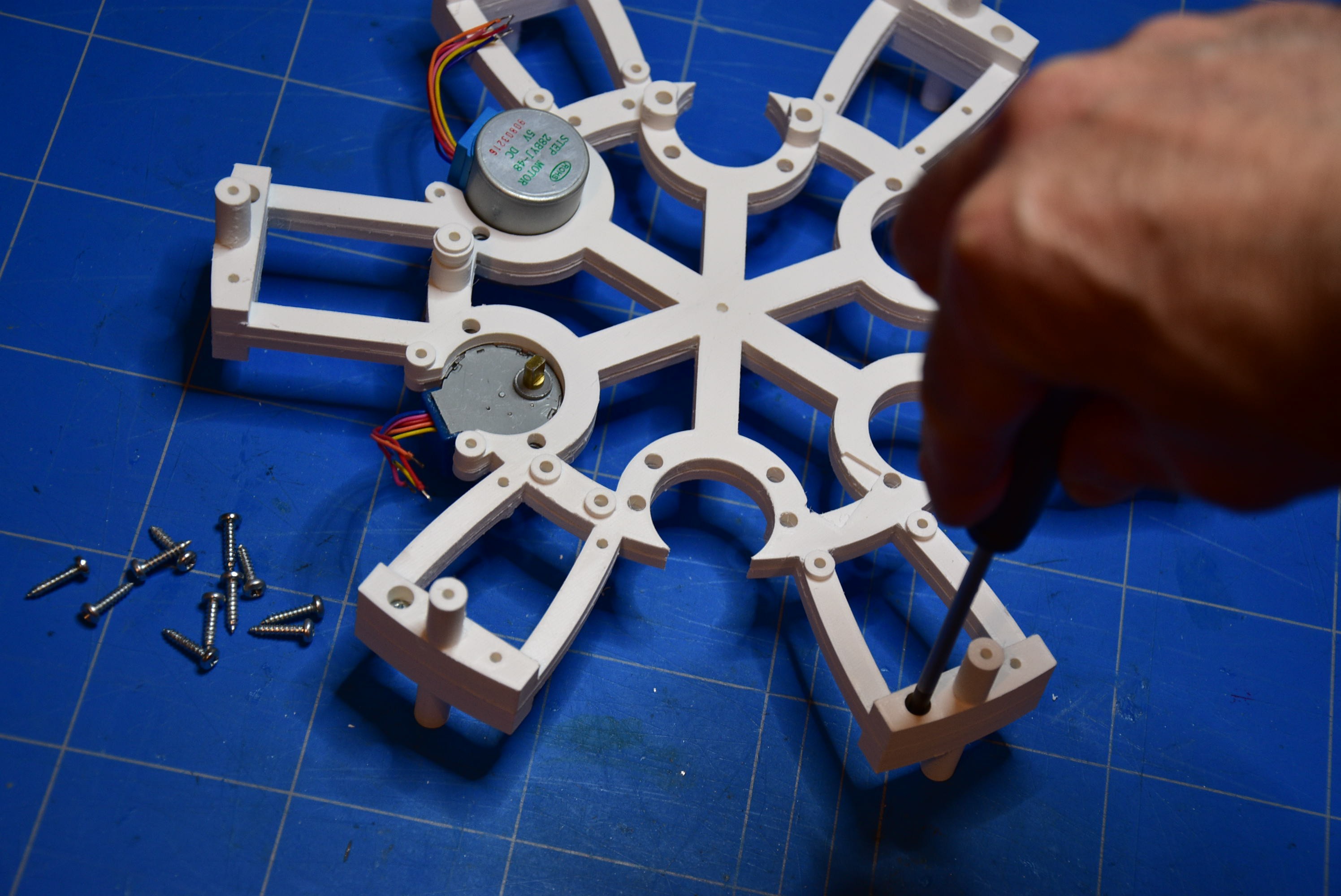
Cover this with the other part of the frame and fix them together with the screws (2,9mm x 13mm).
![]()
Assemble all the other stepper motors to the frame and fix them with the bolts (M4 x 20mm/25mm).
![]()
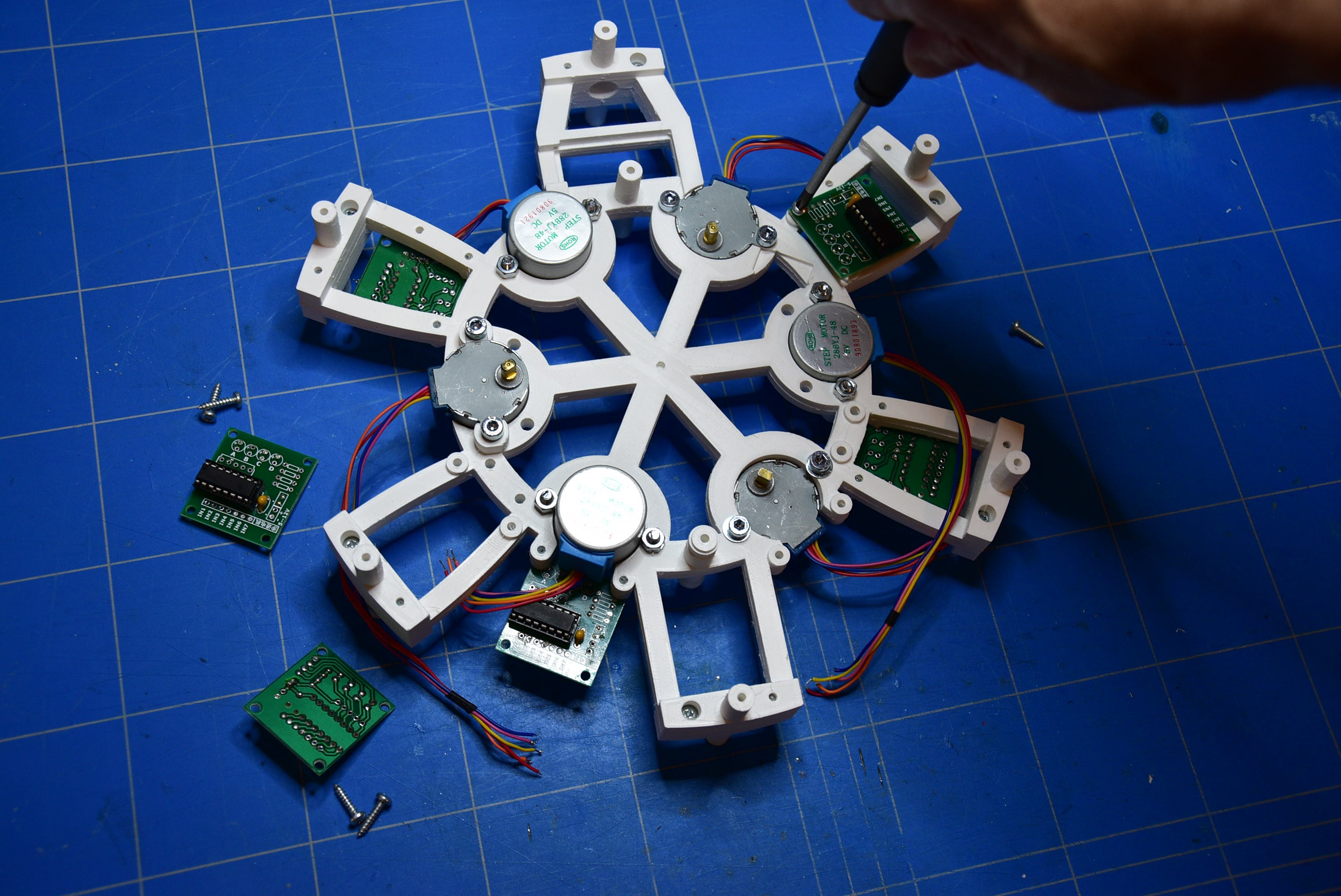
Fasten the ULN2003 PCB's with the screws (2,9mm x 13mm) to the frame in the correct positions.
![]()
Solder the wires of the steppers to the PCB's.
I've noticed that for some stepper motors the colors of the wires are ordered in another way. So, to solder the wires on the PCB's keep the same sequence as the color positions of the connector that was cut off before.
![]()
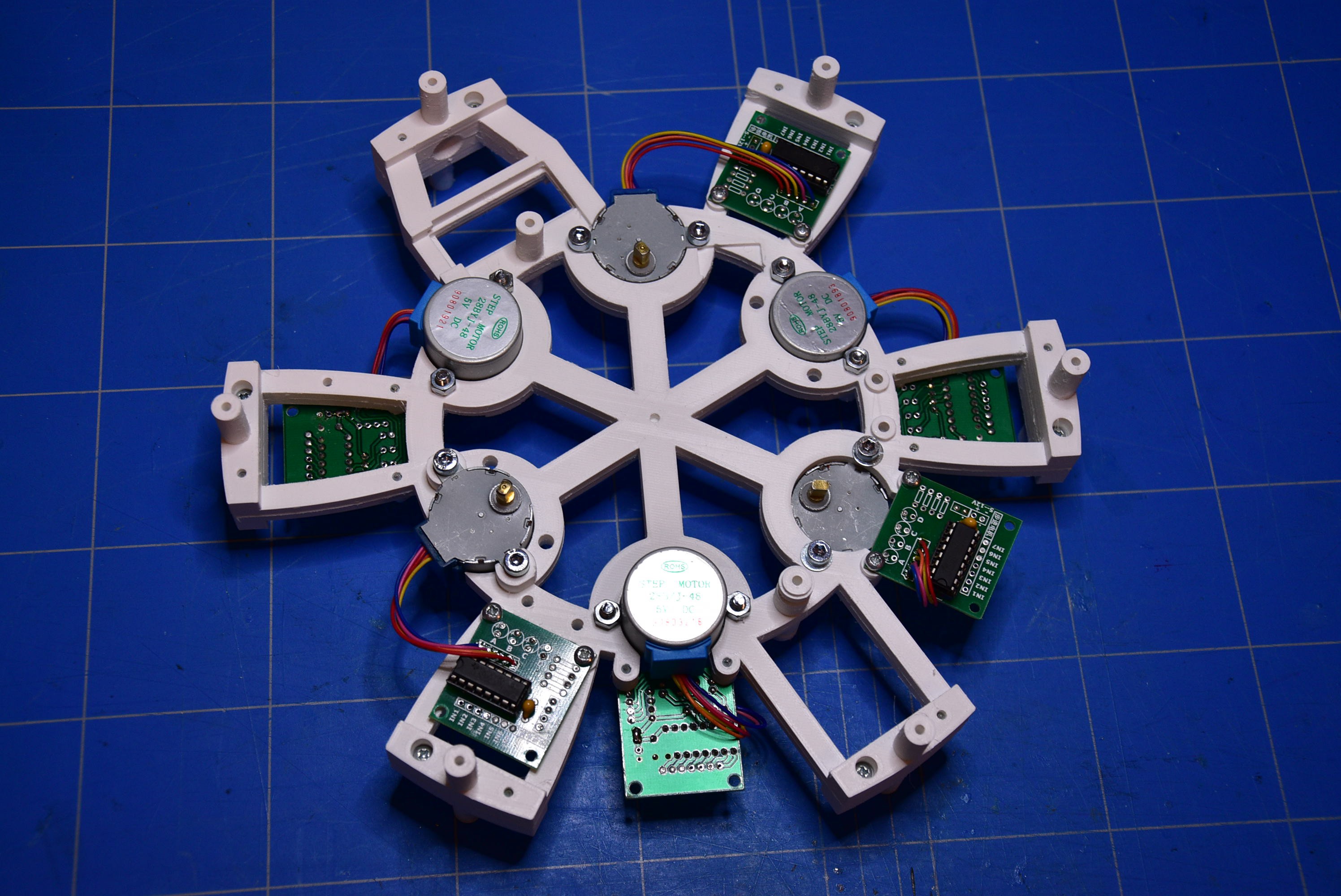
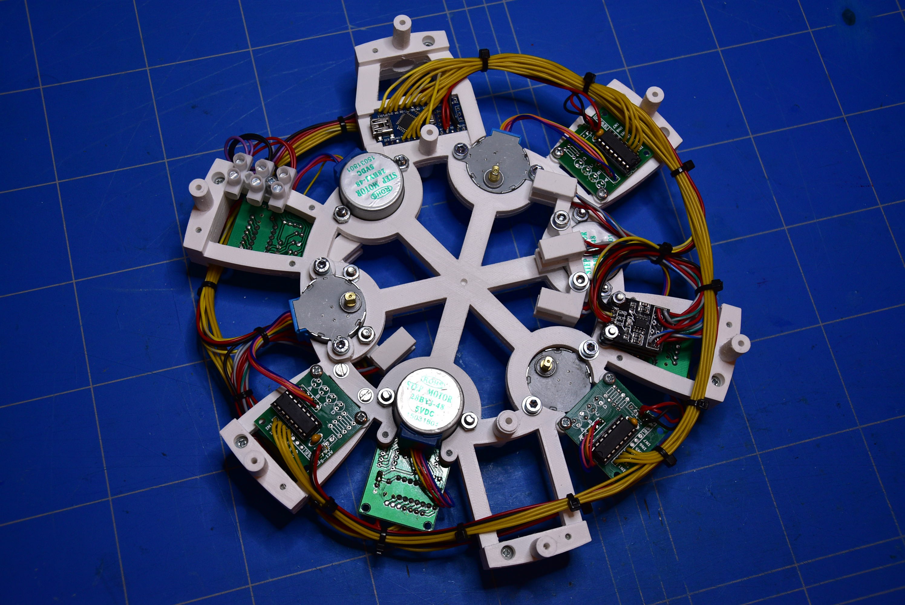
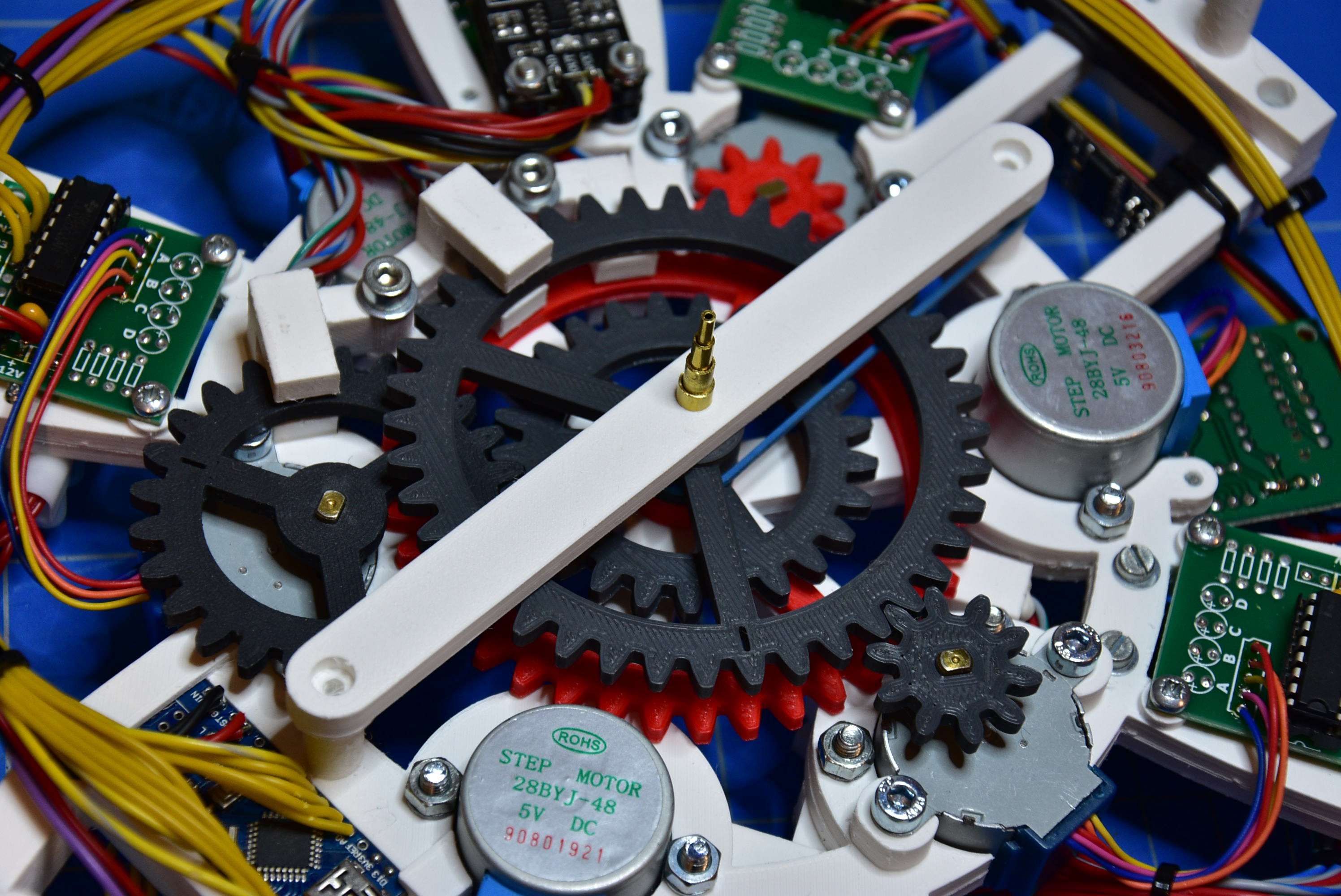
When al this work is finished, you must have an assembly that looks like the image below.
![]()
-
3Clock hand position detectors
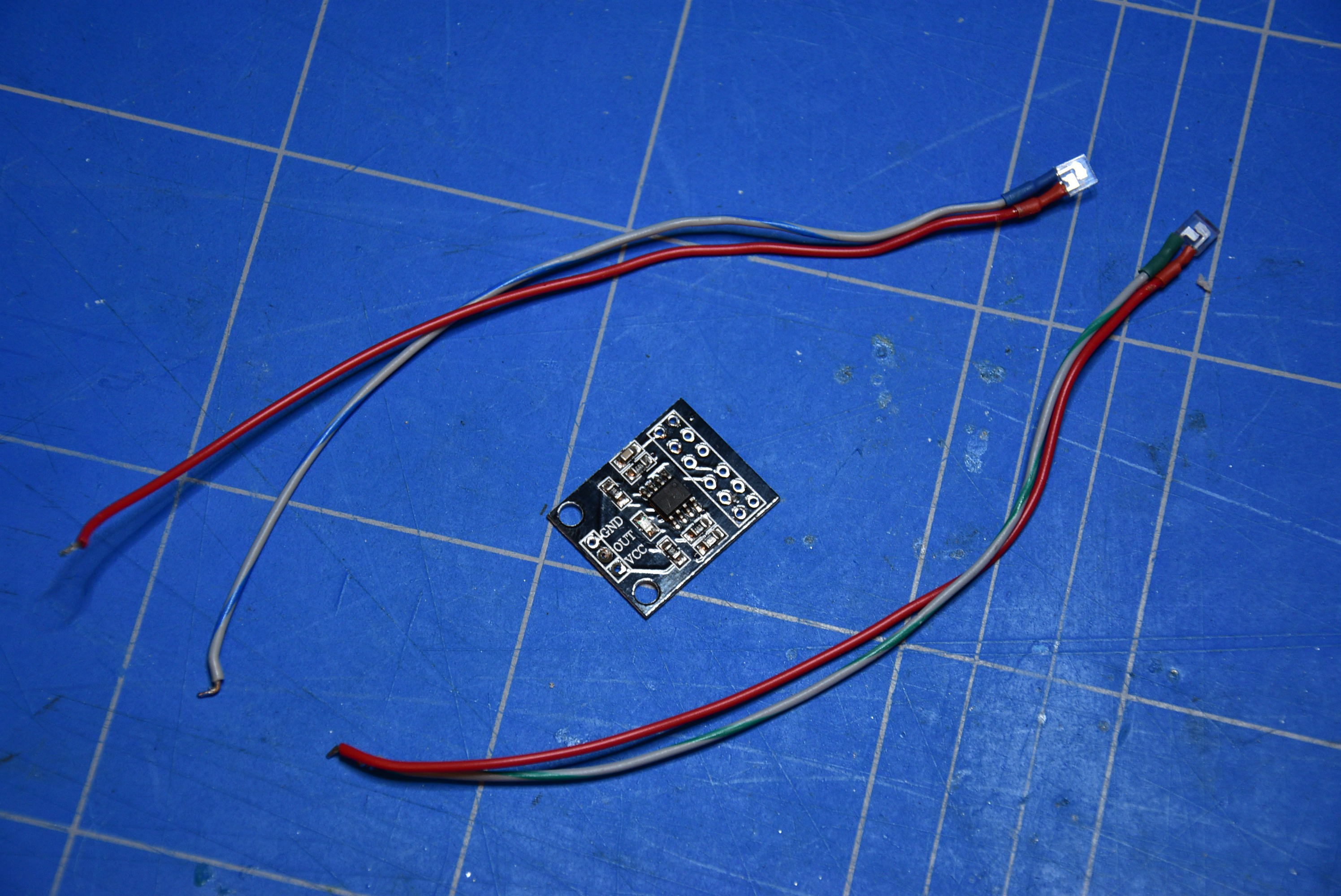
The detection of the position of the clock hands is made by IR detectors.
Take off the hood from the IR detector. Desolder the IR transmitter and the IR receiver, but make a note or set a mark on the components to known how the connection was before ! Solder an extension wire to the pins of the IR transmitter and the IR receiver. Use colored wires so that you can't go wrong and that mistakes are excluded.
![]()
Insert the IR transmitter and the IR receiver into the 3D printed detector frame. Close the gap with some putty.
![]()
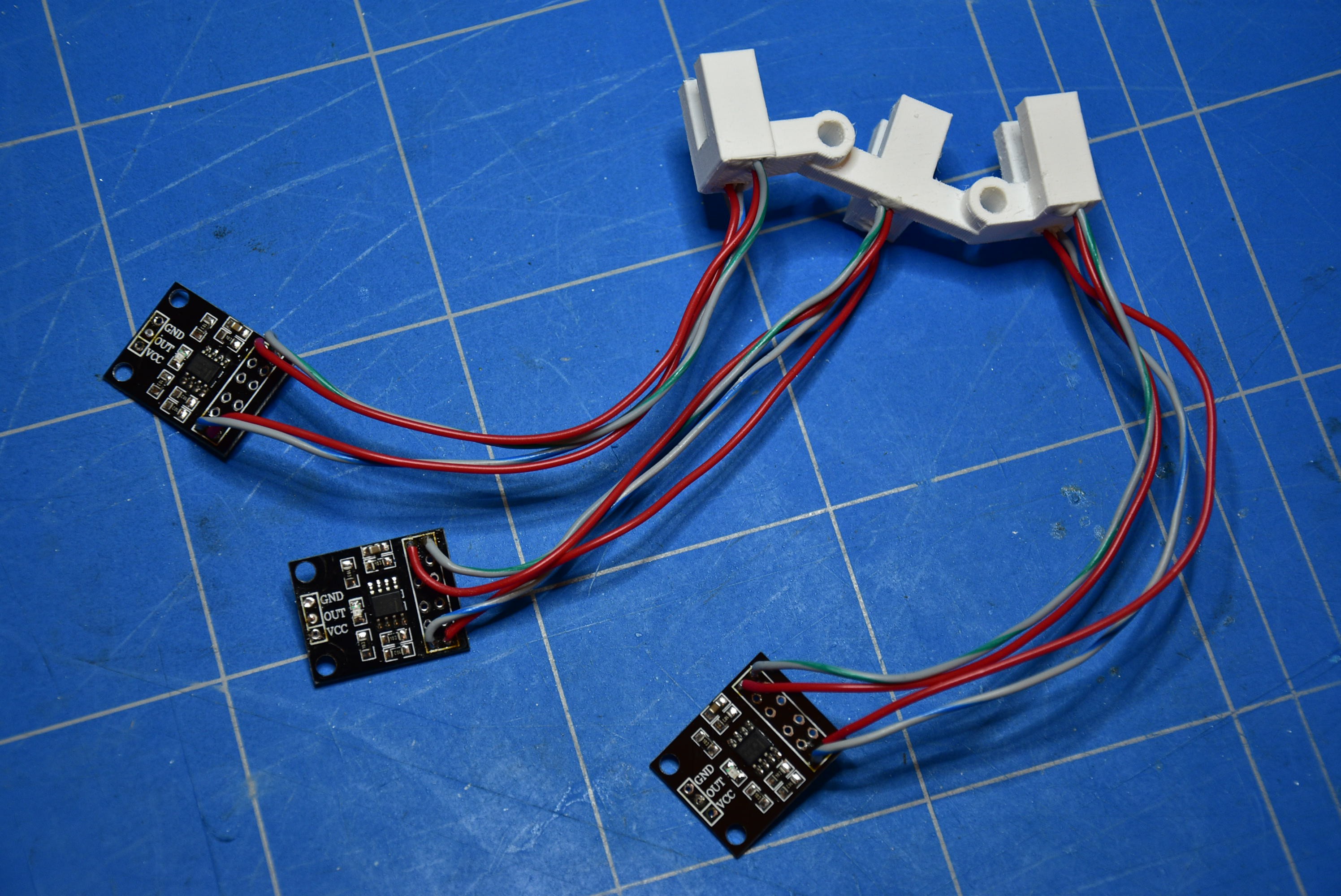
After preparing the three detectors, you should get an assembly like this.
![]()
Put the three detectors together with a M3 bolt (M3 x 30mm) and some spacers. For each channel, on the 'OUT' pin, connect a wire of about 30cm long. Solder a strap through the PCB so that the 'GND' pins and 'VCC' pins are connected together.
![]()
Attach the detector assembly to the frame. Also solder a black and red wire to the 'GND' and 'VCC' pins, with a length of 30cm.
![]()
Finally, the construction should look like this.
![]()
-
4Connections to the Arduino
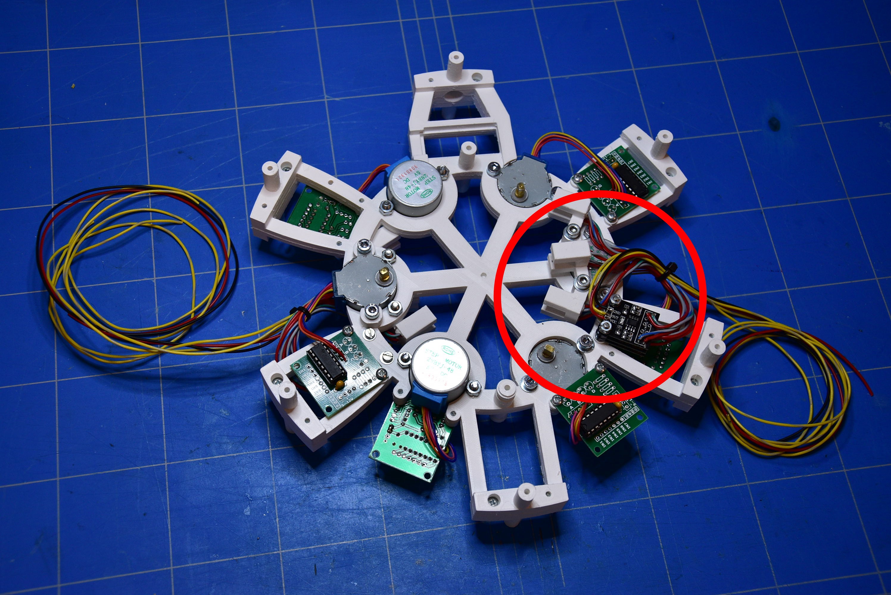
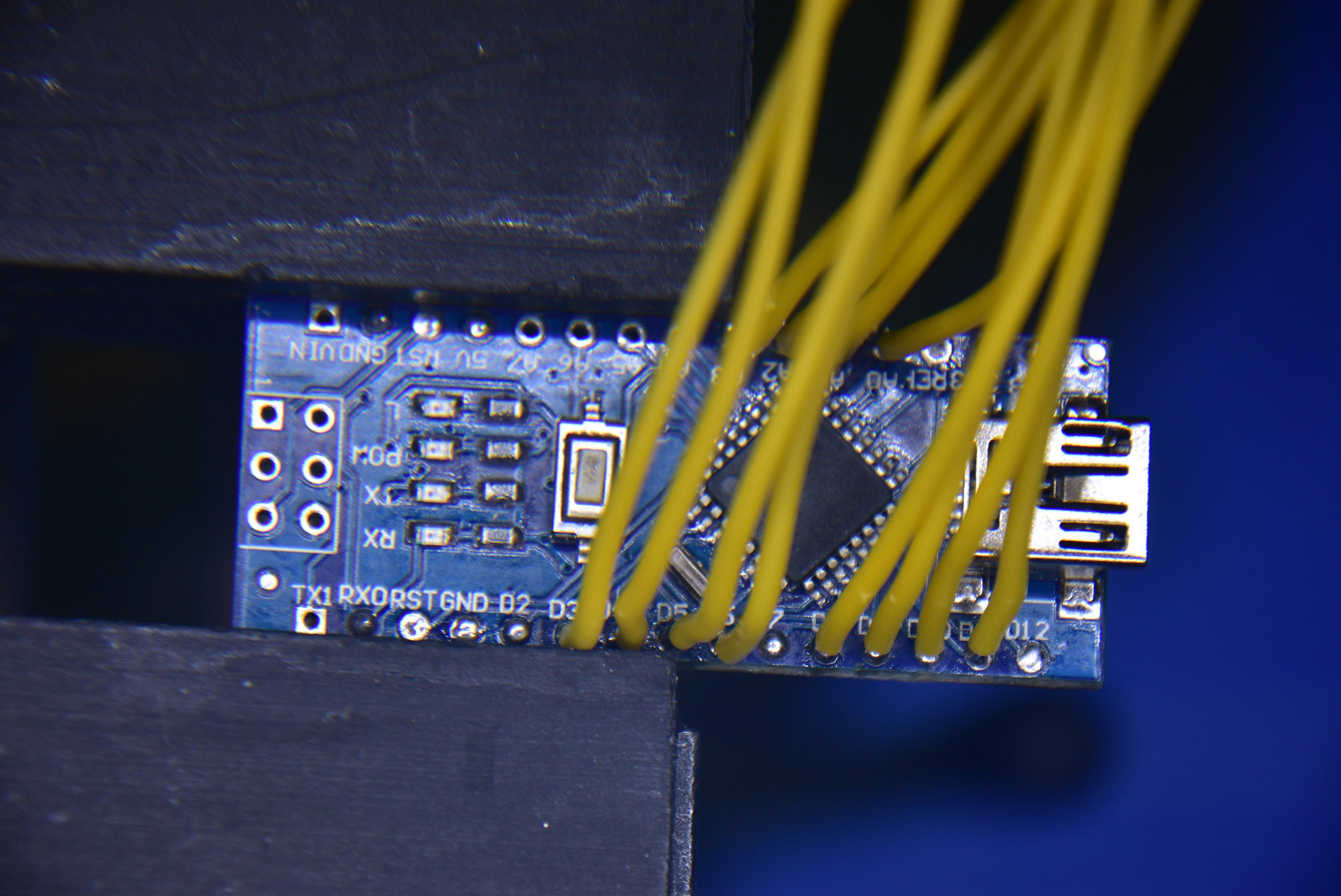
As you can see in the table on the notebook, solder the wires on the ULN2003 driver boards and connect them to the corresponding Arduino pins.
The detector and the stepper motor, most below positioned, are for the seconds gear. The detector and the stepper in the middle belong to the minutes gear and the upper detector and stepper are for the gear which controls the hours.
![]()
![]()
-
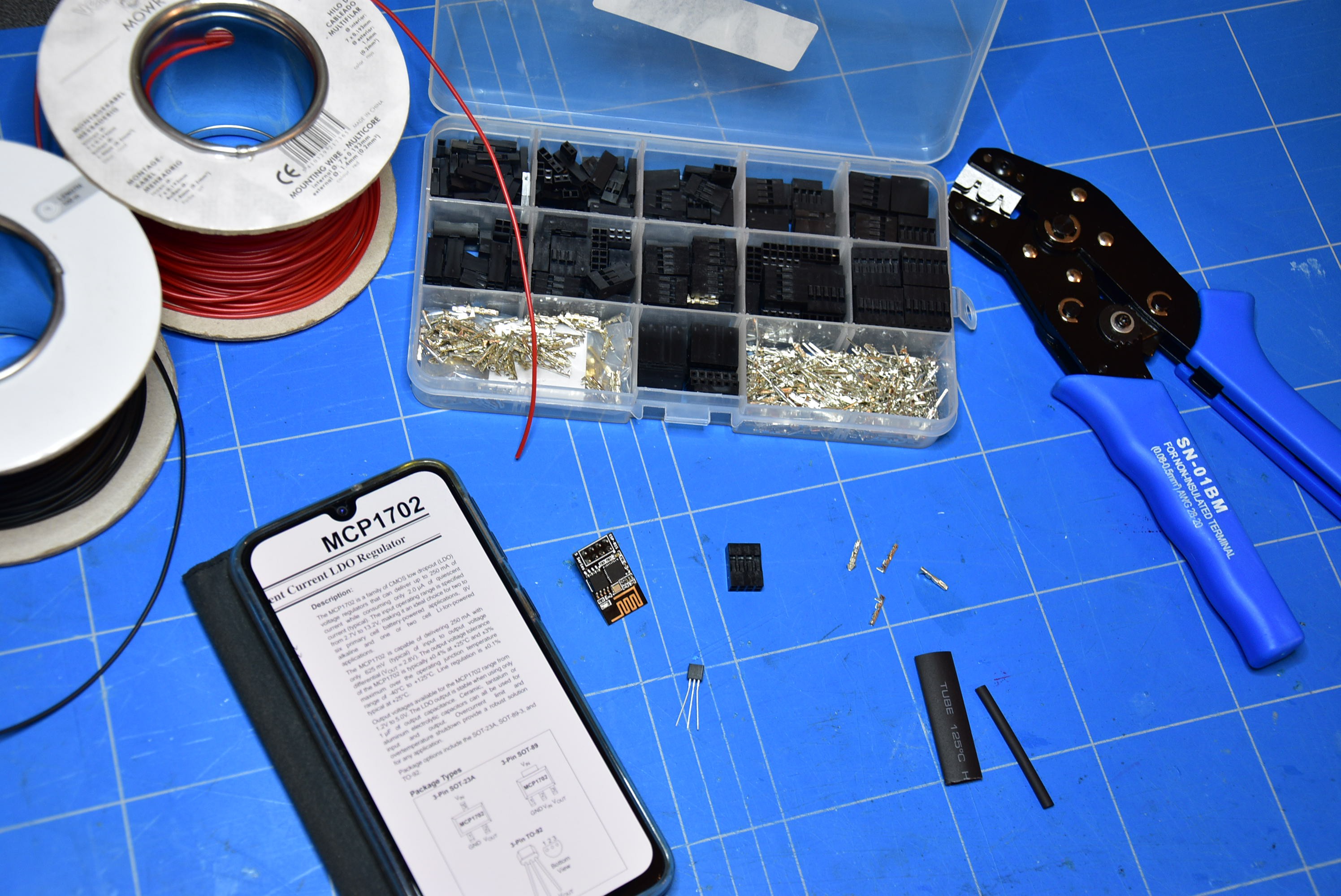
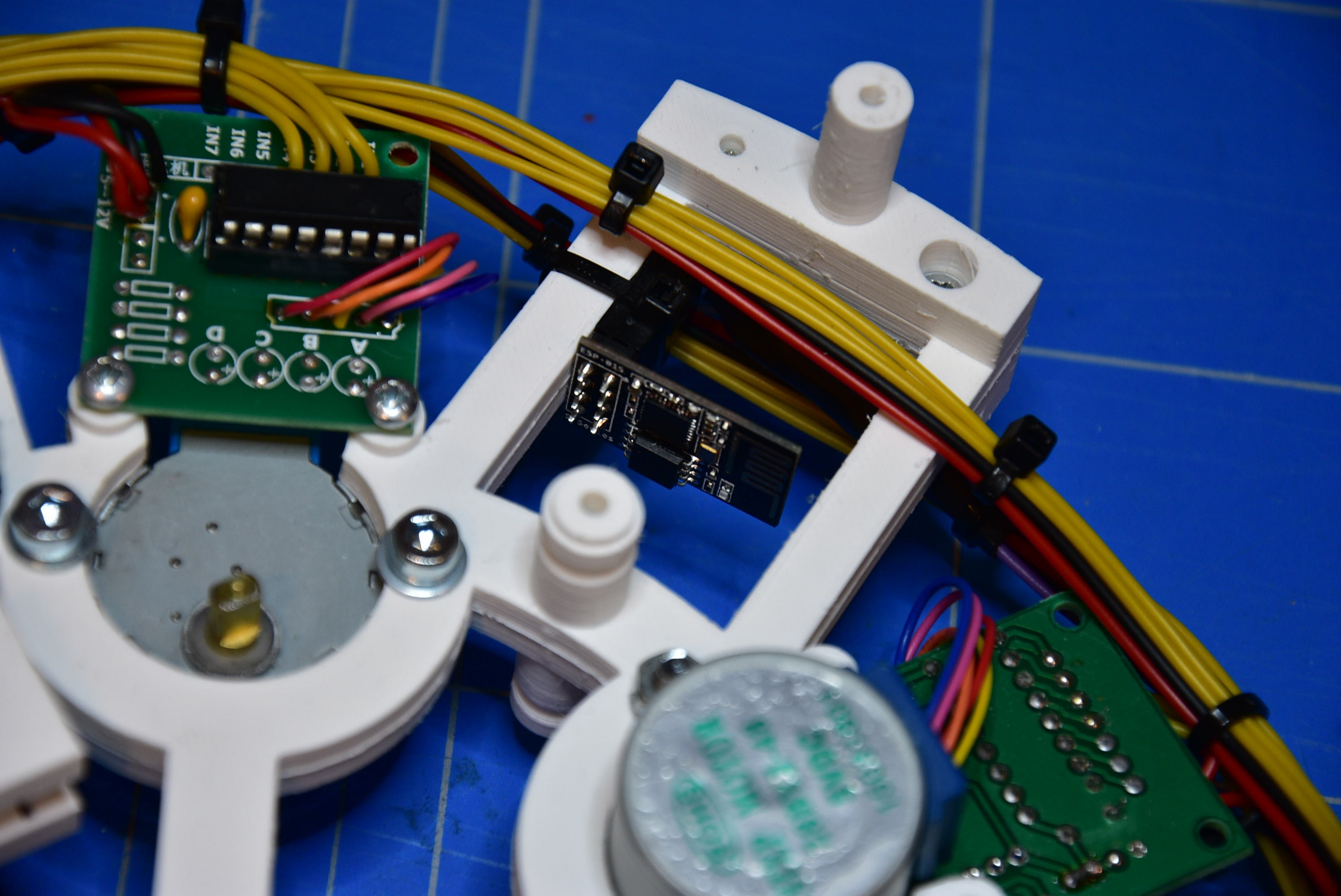
5The ESP-01 WiFi module
The ESP-01 WiFi module establishes the connection to the network. In this way, the exact time for the corresponding timezone will be obtained. The ESP-01 module works on 3V3. Because the Arduino and the steppermotors have a power supply of 5V, we need to make a voltage convertor. For this, I used a MCP1702 3V3 LDO regulator.
![]()
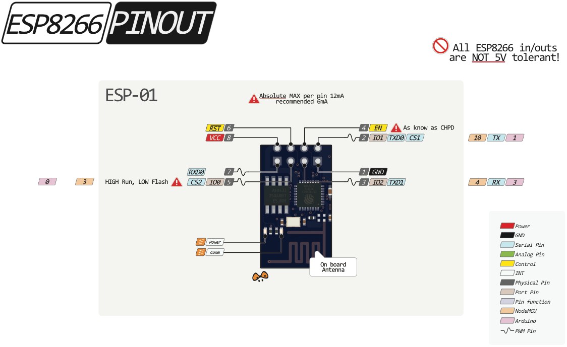
In the table below you can find the connections you have to make.
ESP-01 (Pin) 1 2 3 4 5 6 7 8 GND TXD - EN - - - VCC ![]()
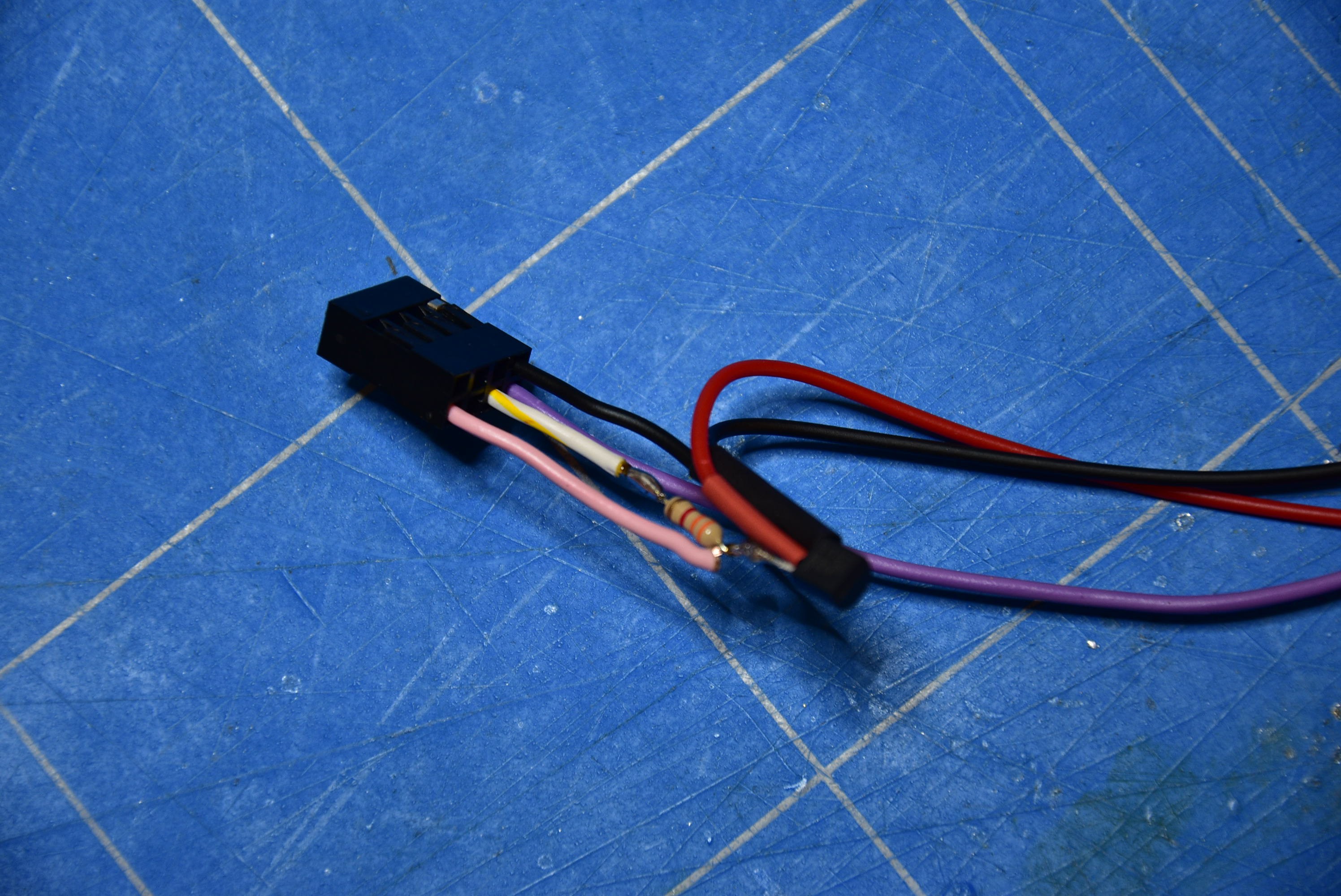
Solder a (red) wire with a length of 30cm to the middle pin of the MCP1702. This must be connected to the 5V. The pin left of the LDO regulator (3V3 output) has to be connected to pin 8 (VCC) of the ESP-01. Also from this pin, you must solder a resistor of 3K3 Ohms to the pin 4 (EN) of the ESP-01. Pin 2 (TXD) is the output pin and has to be connected to the RXD of the Arduino. Finally, connect the pin 1 (GND) of the ESP-01 to the GND of the MCP1702 and to the GND of the Arduino.
![]()
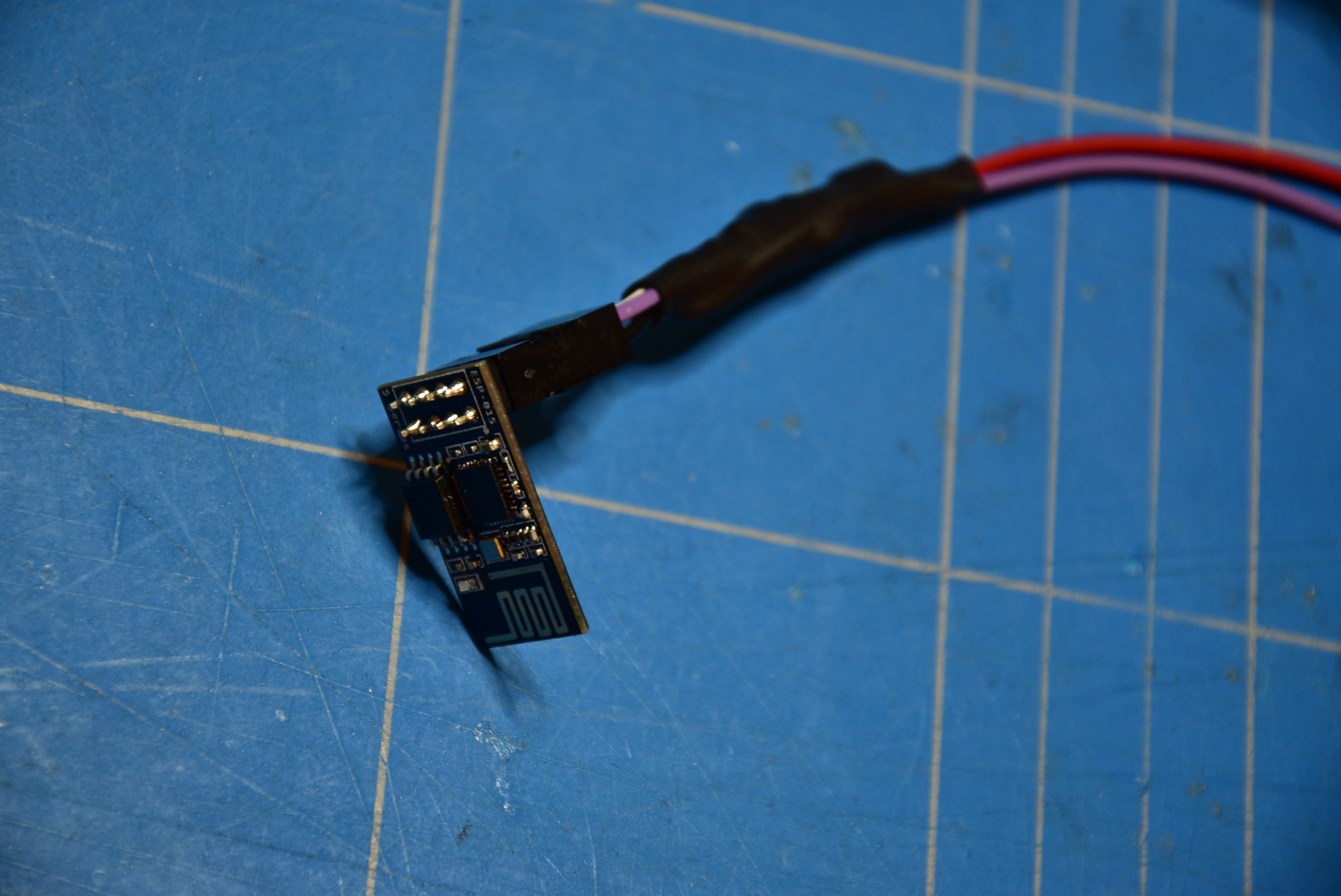
With the help of a heat shrink tube, protect the circuit and clean-up the assembly.
![]()
-
6All the wires together
Use a tie wrap to fix and hold the ESP-01 module in the correct possition.
![]()
For the connection of the power supply (GND / 5V) you can use a terminal block and fix it with a screw (2,9mm x 13mm) to the frame.
![]()
Make the wire bundle clean and proper, with tie wraps. After all the connections are made, your work should look like this.
![]()
-
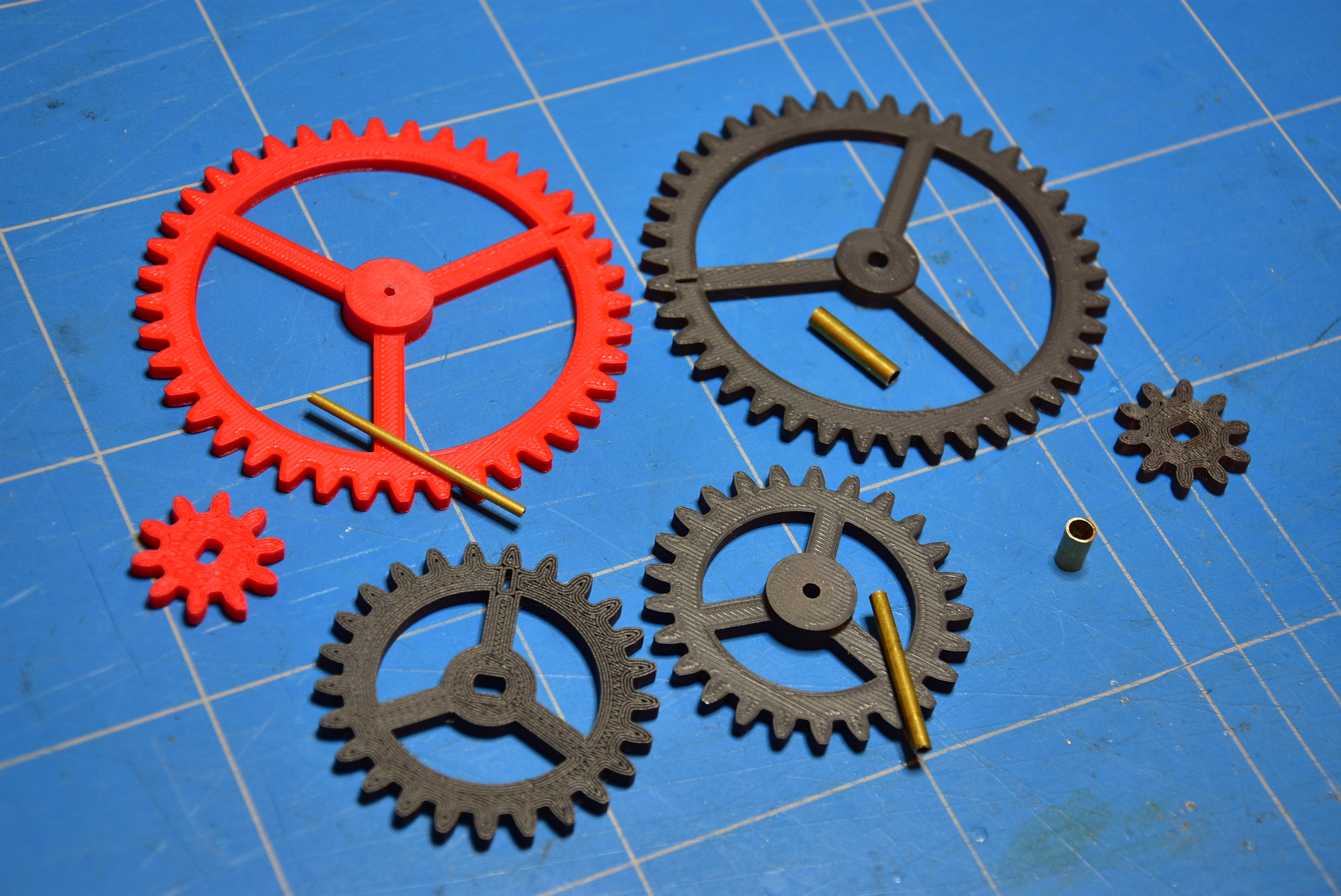
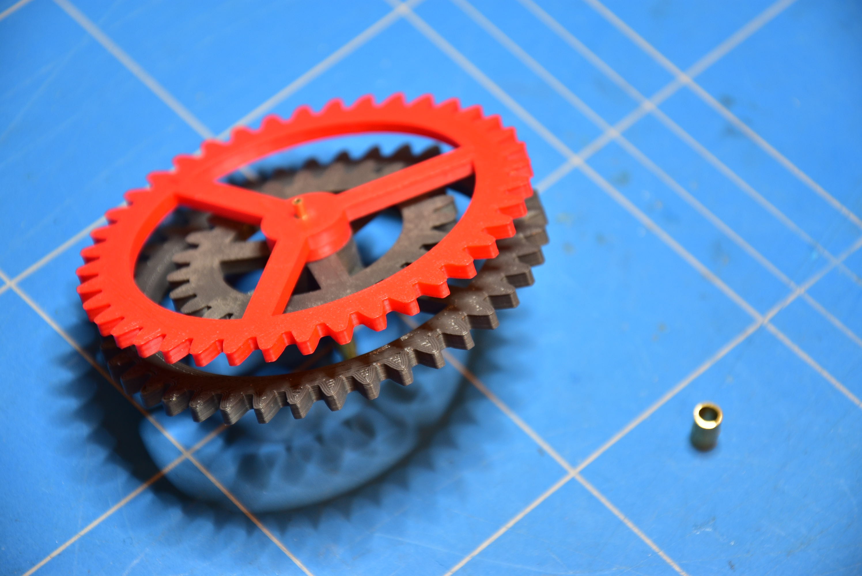
7The gears and the shafts
Start printing the gears. There are 12 gears in total you have to make (6 gears for a single sided clock). If you want, for a nicer view, you can use different colors for the hours, minutes and seconds.
You also need 4 axles with different diameters and different lengths.
- for the seconds: 2mm shaft with a length of 42,5mm
- for the minutes: 3mm shaft with a length of 29mm
- for the hours: 4mm shaft with a length of 18,5 mm
- in the middle of the frame: 3mm shaft with a length of 3mm
![]()
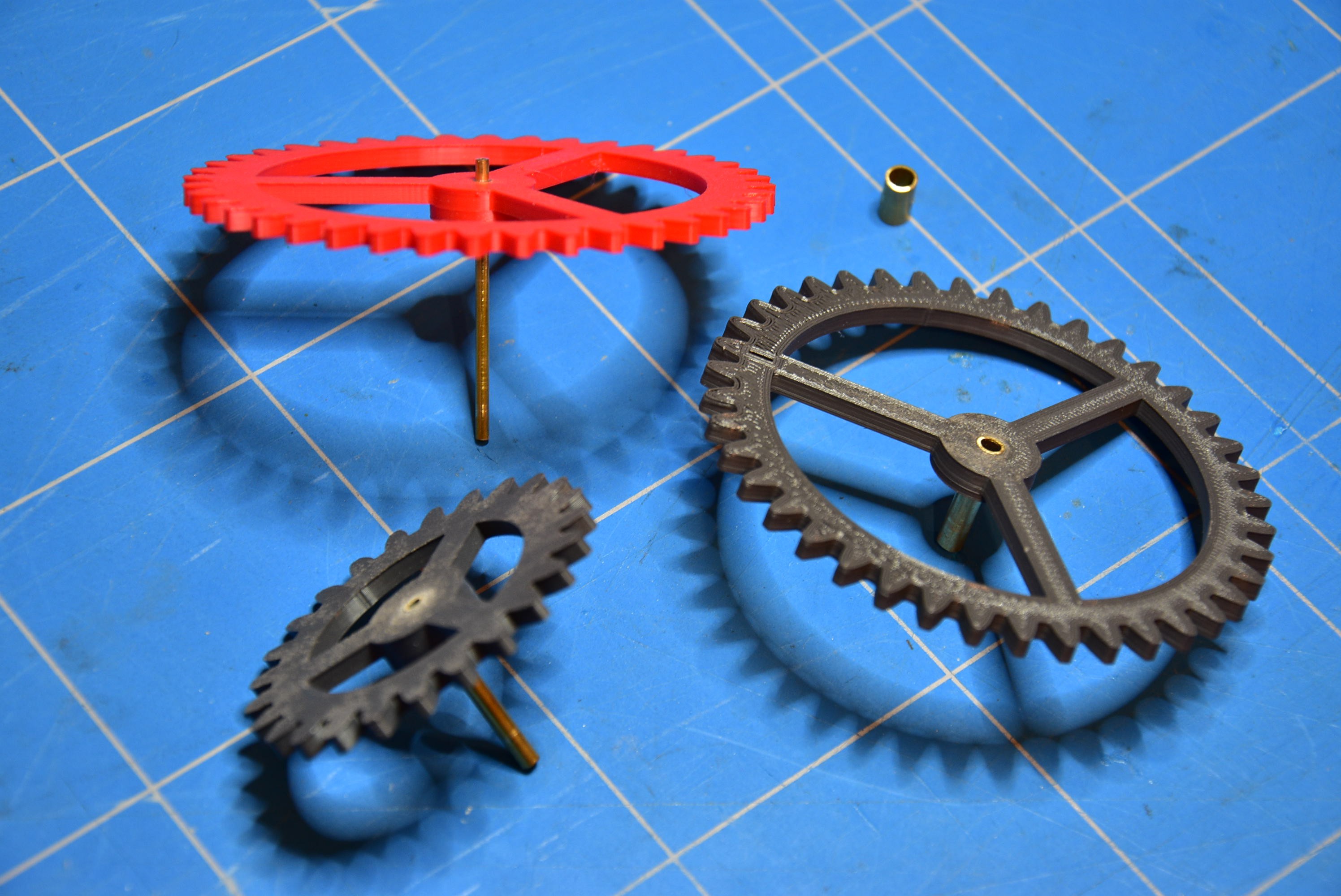
With some glue, fix the axle in the center of the corresponding gear.
![]()
Assemble the three gears together. Make sure they can spin freely and there is as little as possible friction between the gears.
![]()
In the center of the frame insert the 3mm shaft.
![]()
Set the gears in place.
![]()
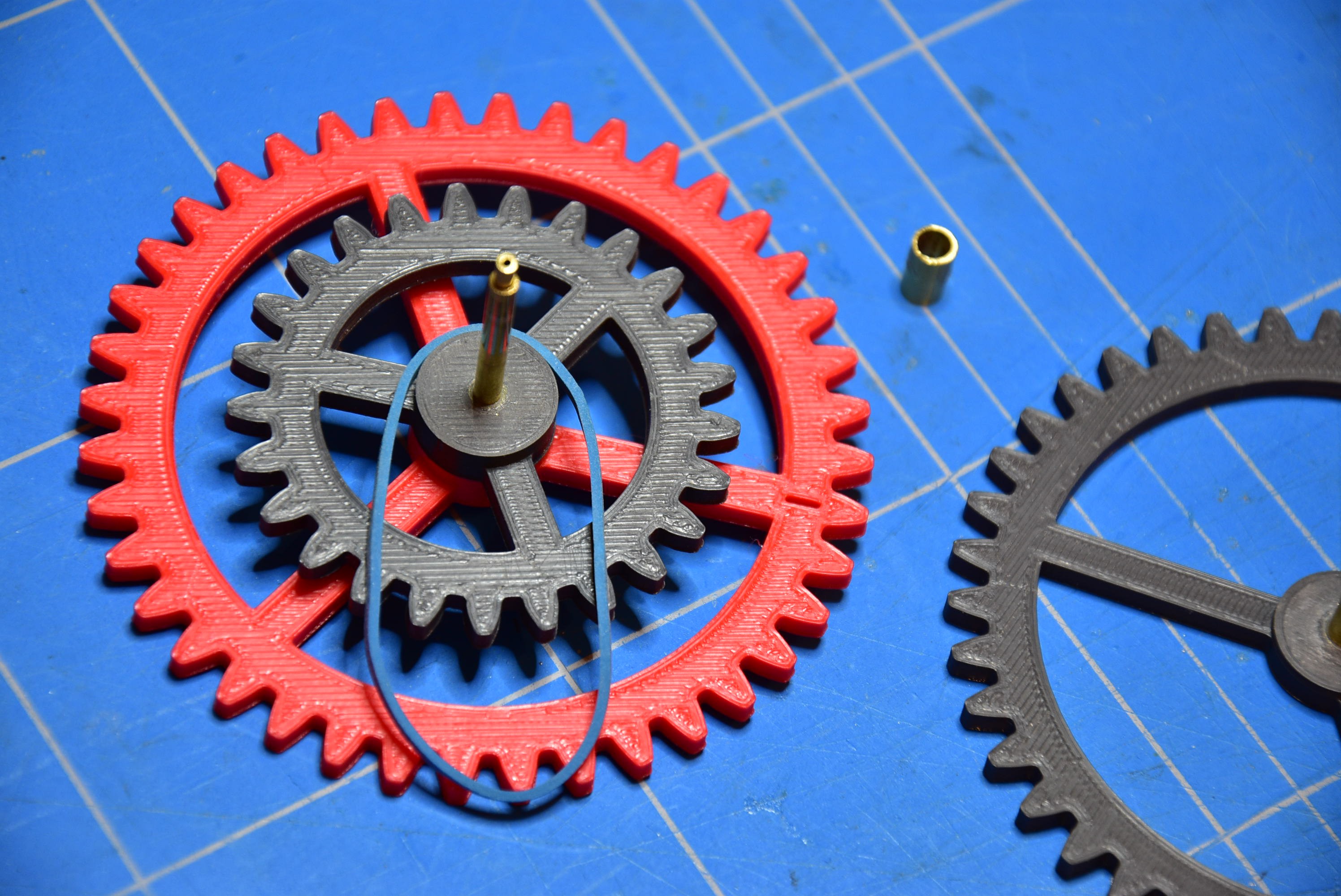
Due to the slack on the gearbox of the stepper motor, I had difficulties during the building of this clock. This slack gives some tolerance at the mark of the minutes hand. To reduce this evil, a rubber band, with a small tension, can solve this problem. However, later, I got a golden tip from my friend Jan G.. When you add a little grease (e.g. vaseline) between the minutes and the hours gear, it gives a little resistance to the minutes hand and so, this will also reduce the slack.
![]()
![]()
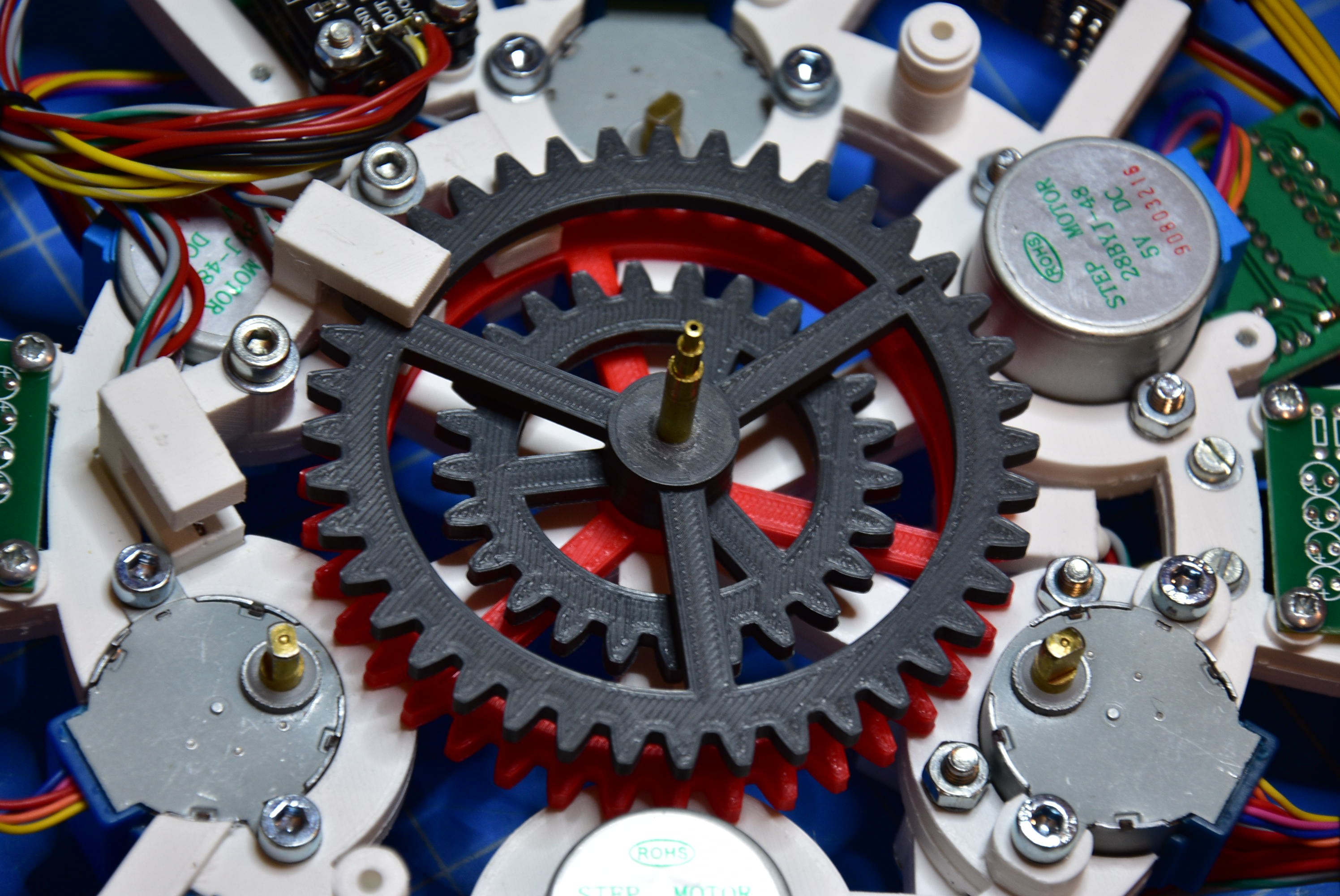
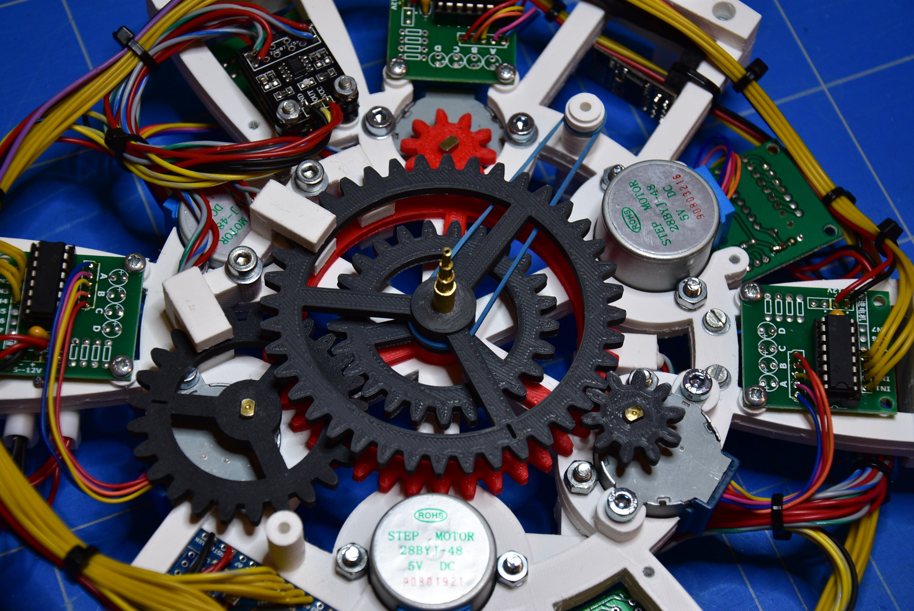
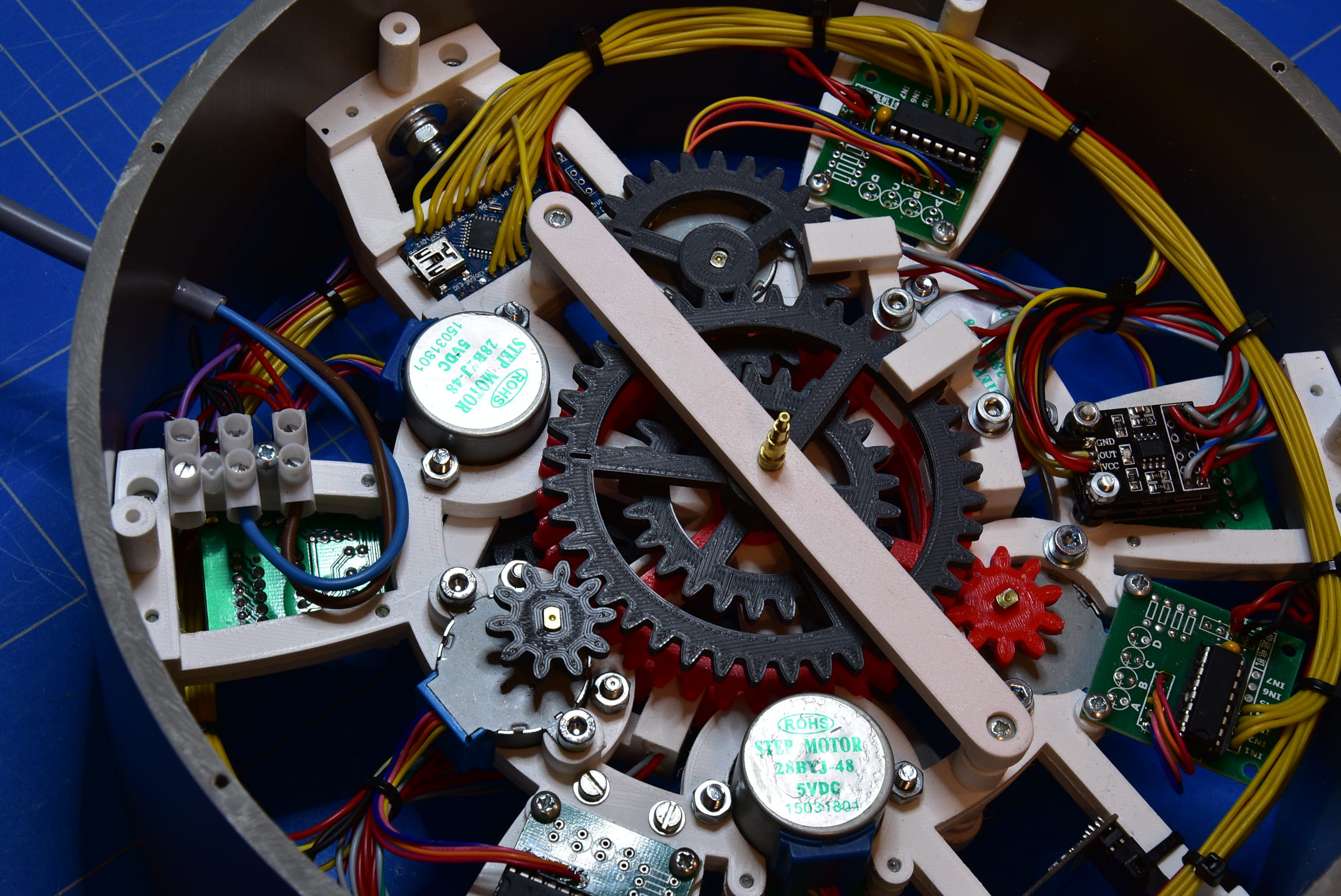
Now it's time to place all the gears to their (motor) positions.
![]()
Take the holder and insert a shaft of 5mm diameter, with a length of 8mm, in the middle. The purpose of this barrier is to hold the gears in place and to reduce the slack.
![]()
Fasten the barrier to the frame with two screws (2,9mm x 13mm).
![]()
-
8Time for testing
Now that all the connections are made, it's time to test our device. Before you can do this, you have to program the Arduino and the ESP-01. The source code for this controllers could be found in annex. The ESP-01 has to make a connection to a network via WiFi. Therefore, in the code, you must enter your credentials (login and password).
When the power is turned on, the ESP-01 will try to make connection with the network. If this routine has passed successfully, a blue LED will light up. Now, the ESP-01 is connected to the network and the time information is sent out on the TXD pin (to the Arduino).
When the Arduino starts up, the steppermotors will be rotated anti-clockwise (the gears of the clock hands will turn clockwise), till the detector reaches the reference position. After this calibration cyclus, the Arduino waits and reads, on the RXD pin, the incoming time information (from the ESP-01). When a new minute begins, the seconds hand starts to turn his cycle and the clock will position the minutes and hours hands to the corresponding markers.
-
9All together now
When the clock mechanism is fully assembled and tested, slide the construction carefully in the body (PVC pipe) of the clock. On the top of the frame, you can fix the bolt where the clock will be hung. The other 'wings' of the frame could be fixed to the body with glue. Keep attention that the frame is exactly positioned in the middle of the PVC pipe !
You may also insert the power (5V) and connect the wires to the terminals.
![]()
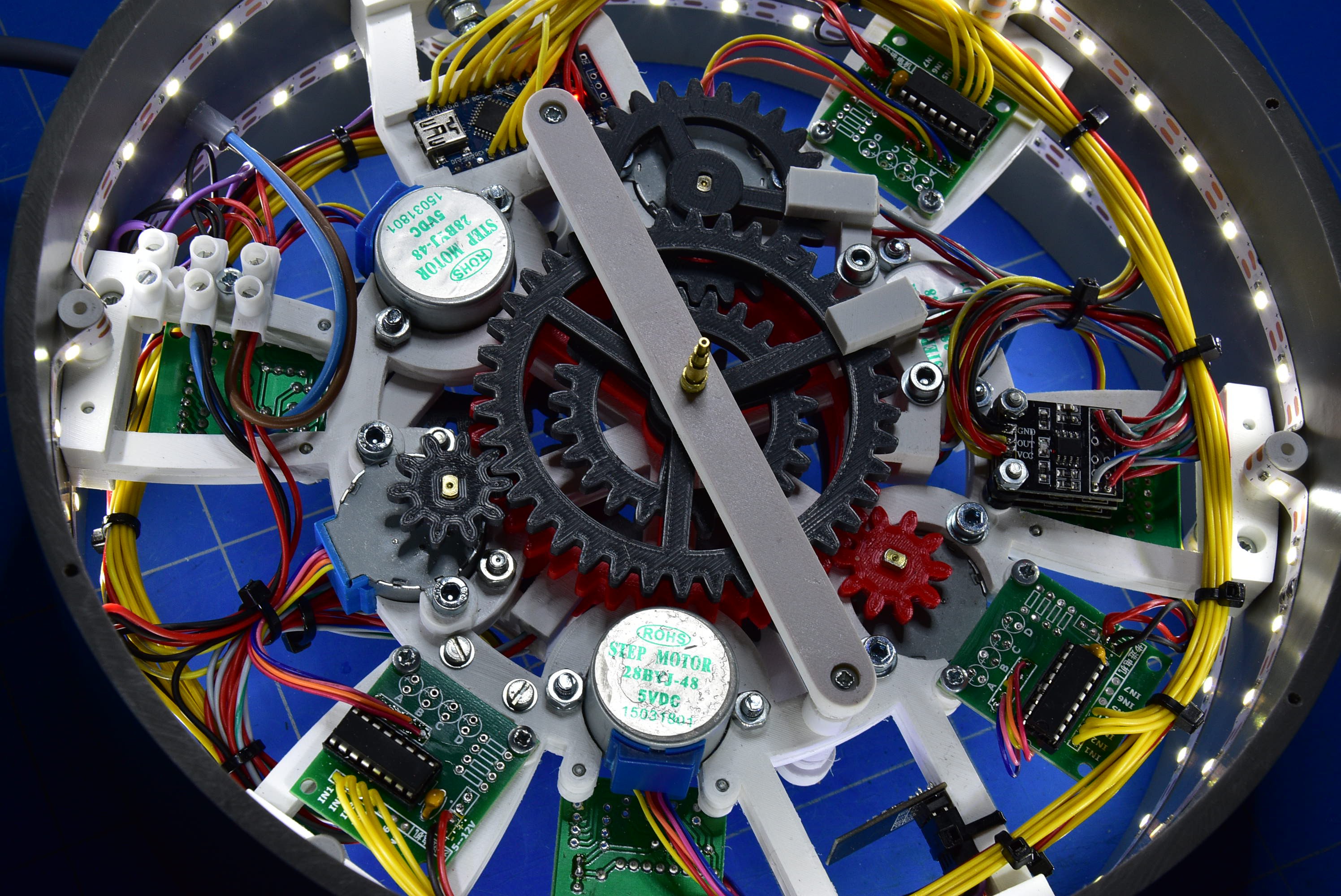
If you like, you can add a LED-strip to illuminate the clock face.
![]()
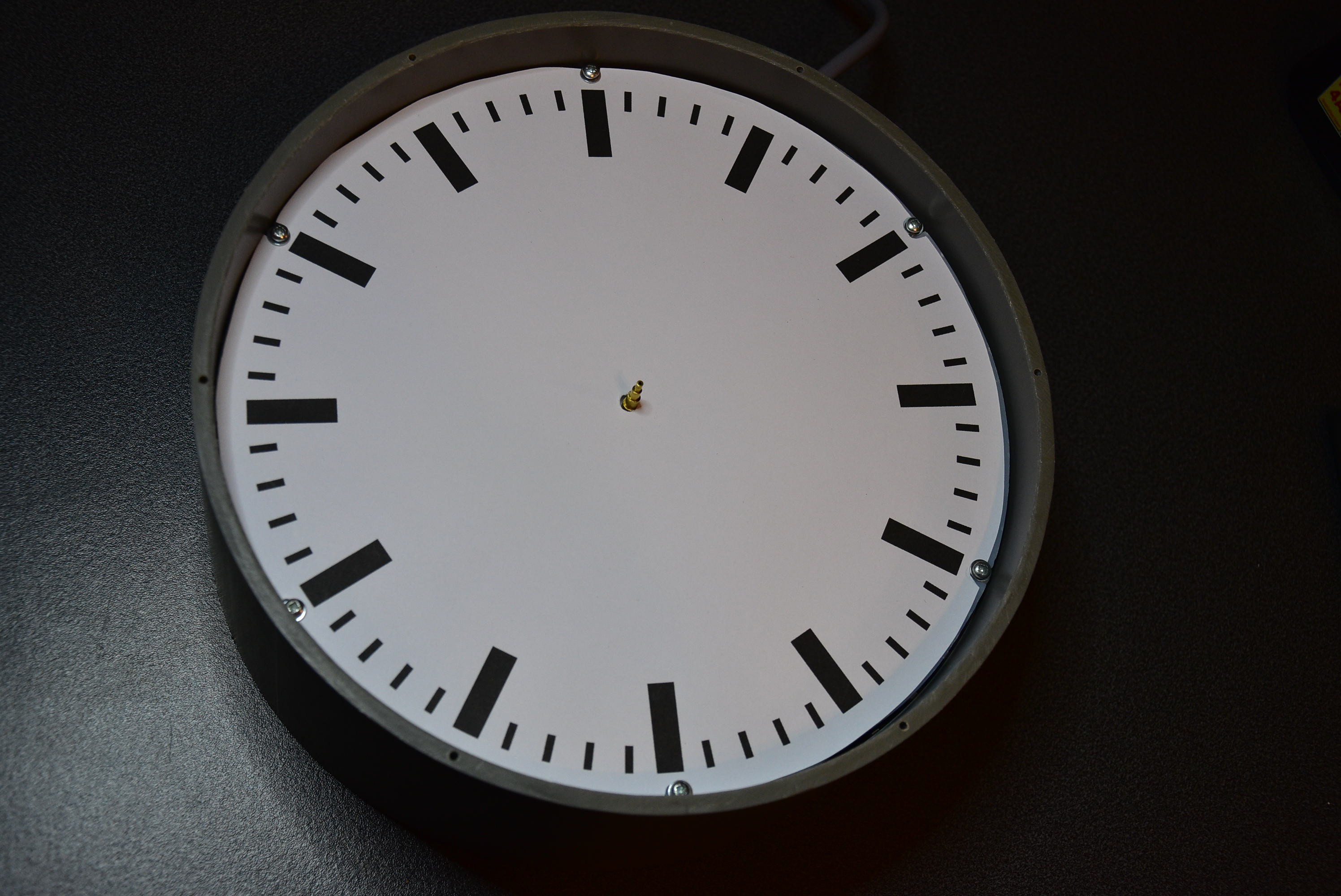
3D Print the inside rings, the outside rings and the clock hands.
![]()
The clock-face must be printed on a A3 paper format. From the layout in SketchUp you can follow this method to print on scale: Print to Scale in SketchUp - CAD Software Support from CAD International
From a crystal clear plexi glass sheet, of 3 mm thickness, saw a circle of 25mm diameter.
From a matte glass sheet, of 3 mm thickness, saw a circle of 24mm diameter. In the middle of the circle drill a hole of 5mm diameter.
For these two sheets, at the border of this circle, make 6 holes of 3,5mm diameter, each over 60 degrees.Fix the matte glass circle and the clock-face with 6 screws (2,9mm x 13mm) to the frame of the clock mechanism.
![]()
Set the hours, minutes and seconds hands to the shafts.
Now it's time to calibrate the clock (hands). Set on the power. The clock will start to find his origin points (refer to instruction 8). When it's done, you should set the clock hands to the most upper vertical position.
![]()
After the calibrating is done, the clock will start to work automatically. The last thing is to close the clock with the plexi circle and the outer protection ring. Use 6 screws (2,9mm x 13mm) for sealing the clock.
![]()
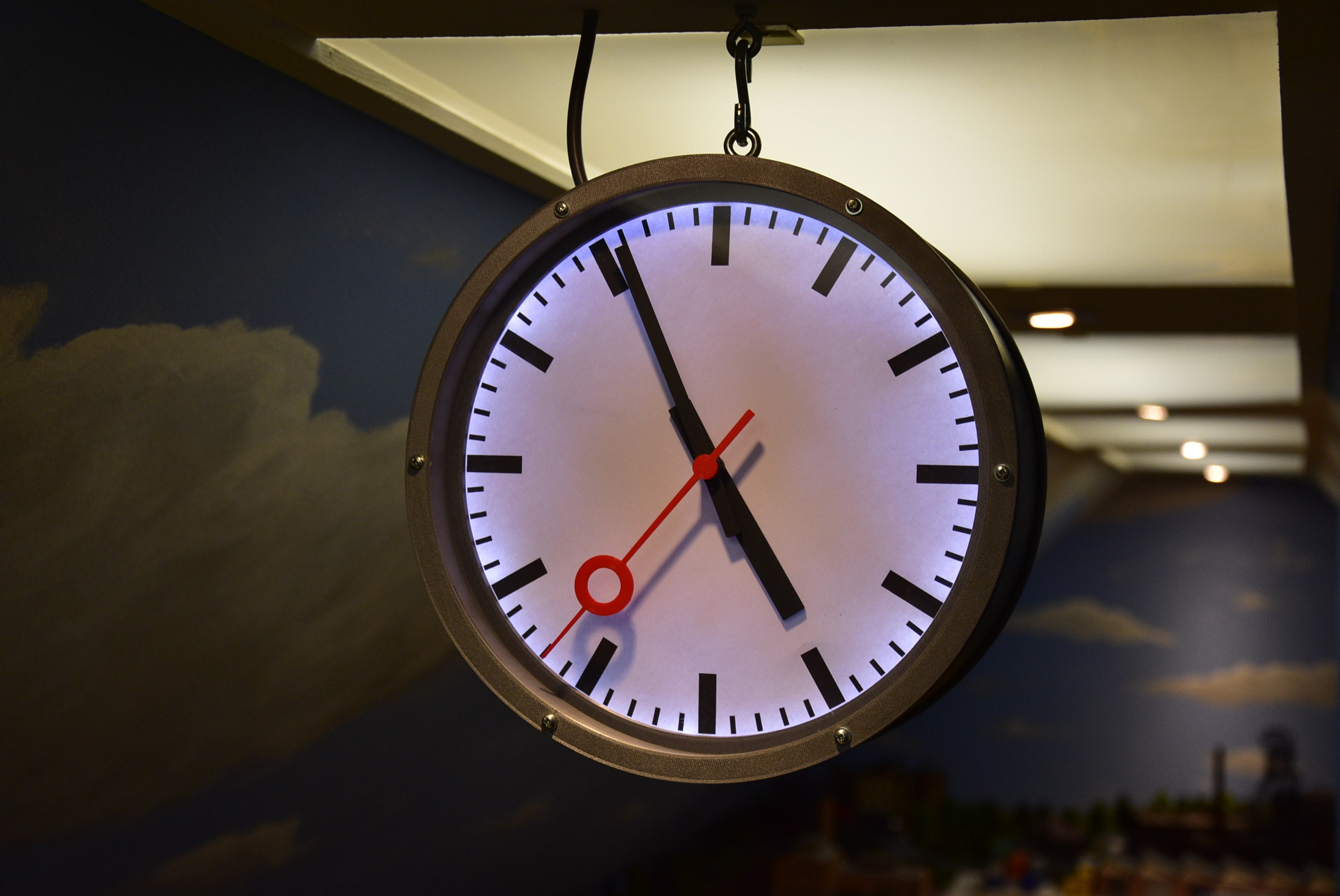
Belgian Railway Station Clock
A 3D printed, double sided view, Belgian Railway Station Clock, synchronized with the network time.


Discussions
Become a Hackaday.io Member
Create an account to leave a comment. Already have an account? Log In.