0%
0%
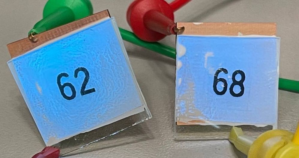
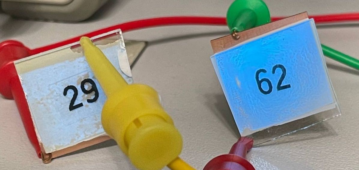
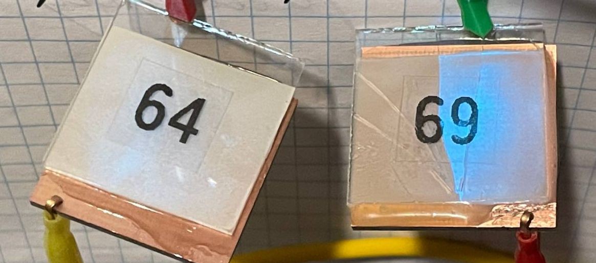
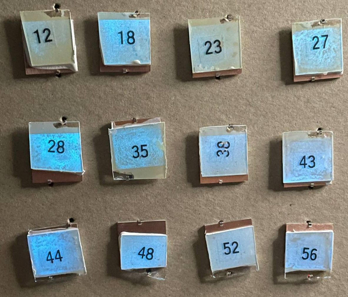
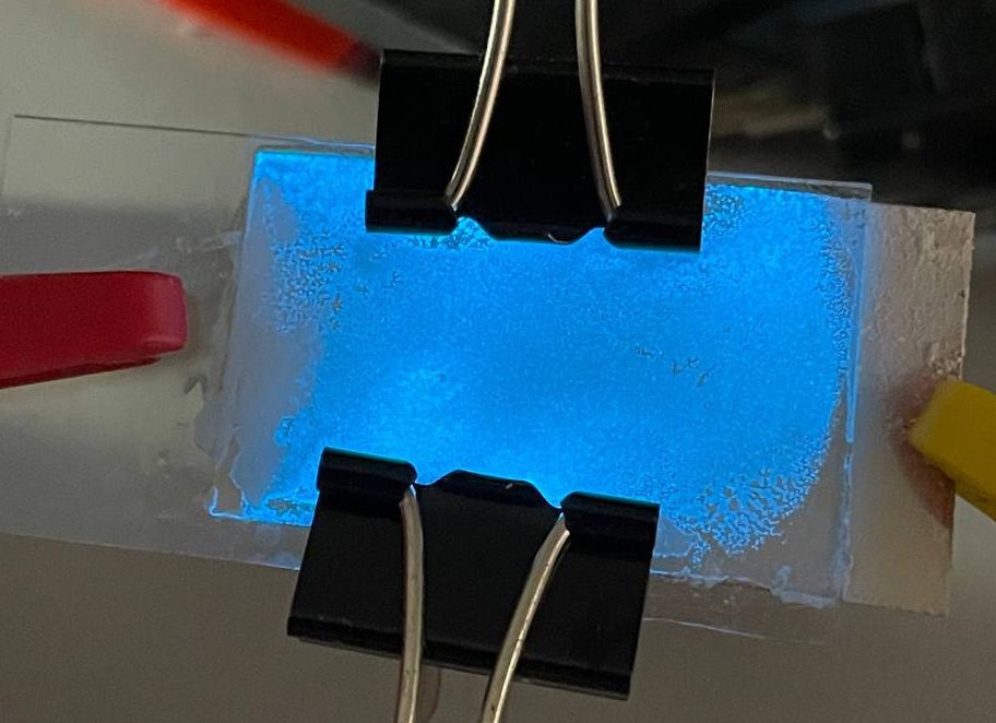
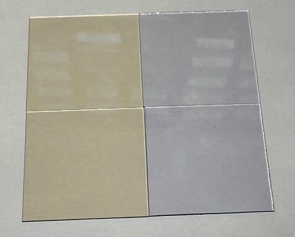
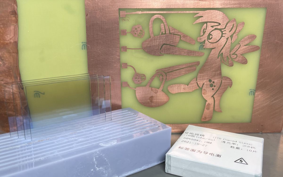
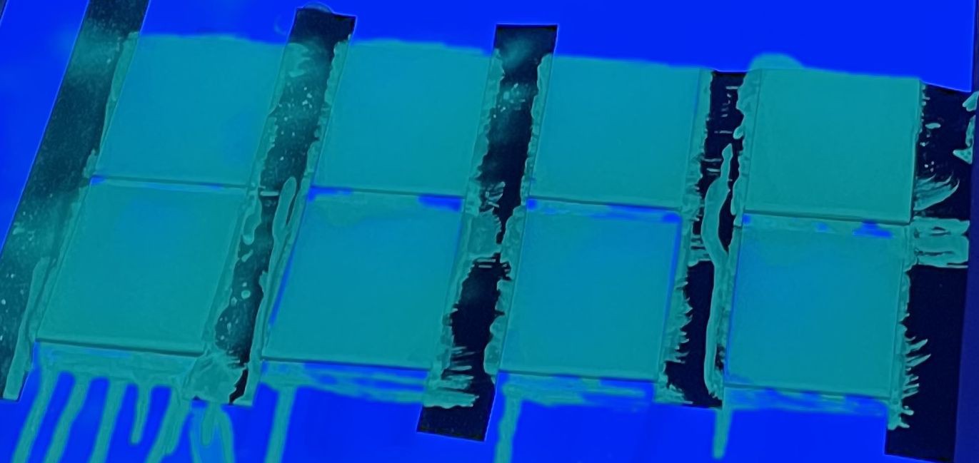
Self-made EL segment displays
How to make your own display with almost any configuration just using a paintbrush
 Artem Kashkanov
Become a Hackaday.io member
Already have an account? Log in.
Just one more thing
To make the experience fit your profile, pick a username and tell us what interests you.
Pick an awesome username
hackaday.io/
Your profile's URL: hackaday.io/username. Max 25 alphanumeric characters.
Pick a few interests
Projects that share your interests
People that share your interests

 MS-BOSS
 Wriju
Wriju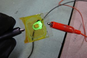
 furan
furan
 Quinn
Quinn
Hi,
Nice project! Where did you buy the electroluminescence phosphor?