 Artem Kashkanov
-
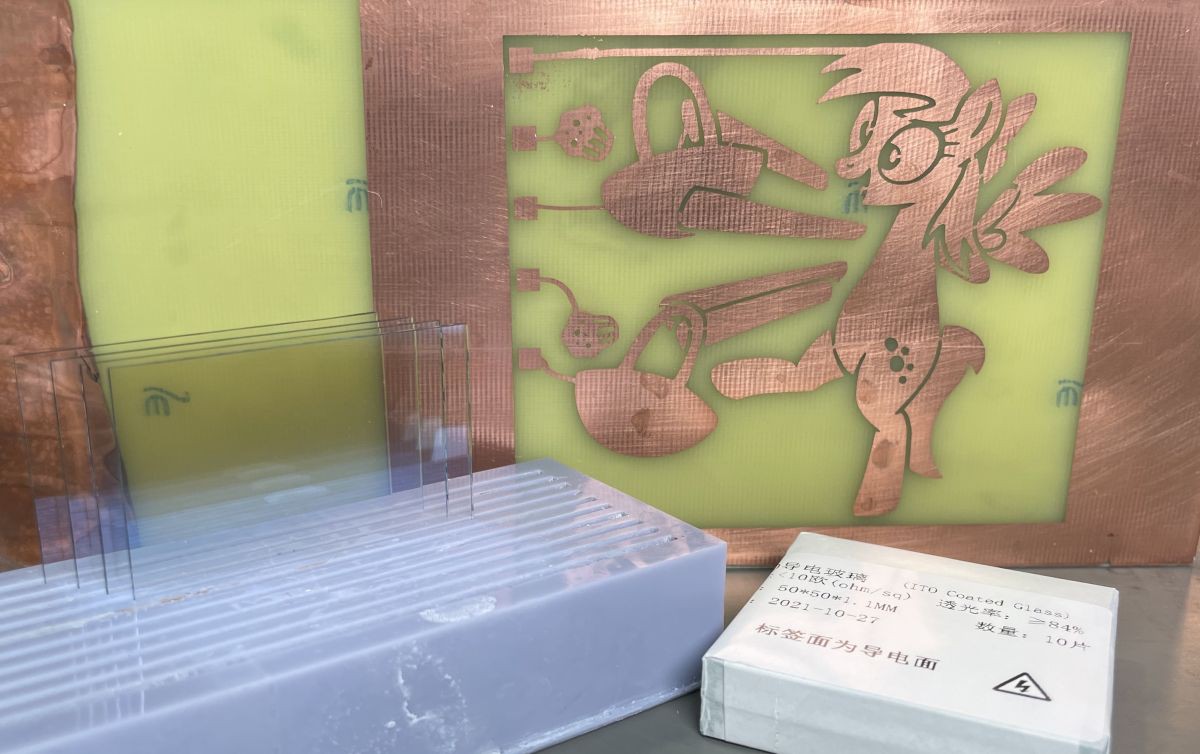
1Step 1: Prepare transparent top layer
ITO glass is the best solution for top plate. I use glass 50x50mm or 100x100mm with conductive layer 10-20 Om resistance
![]()
Кinse the glass thoroughly
-
2Step 2: Prepare back conductive layer
PCB with proper etched image - is the best solution for back plate. Double-side is better, but single-side is also ok - but you need to apply mask when fill emitting layer.
Use immersion gold instead of lead or HASL - to avoid any interactions between EL powder and pcb coating
![]()
-
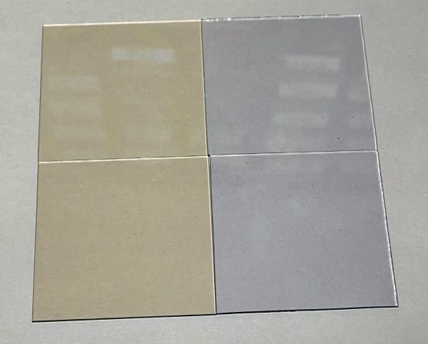
3Step 3: Apply emitting layer
Mix the electroluminescence phosphor in epoxy resin in a ratio of 1.5: 1
You can use ZnS phosphor or Zn2[SiO4]
Epoxy resin must be two-component and has the dielectric constant from 7 to 10. Higher is better. two-component Polyurethane also show good results.
Apply thin layer of the mix to conductive glass. Good thickness is 50-70um
![]()
applied emitting layer under UV light
-
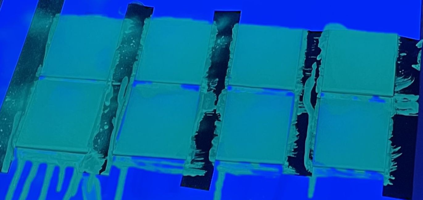
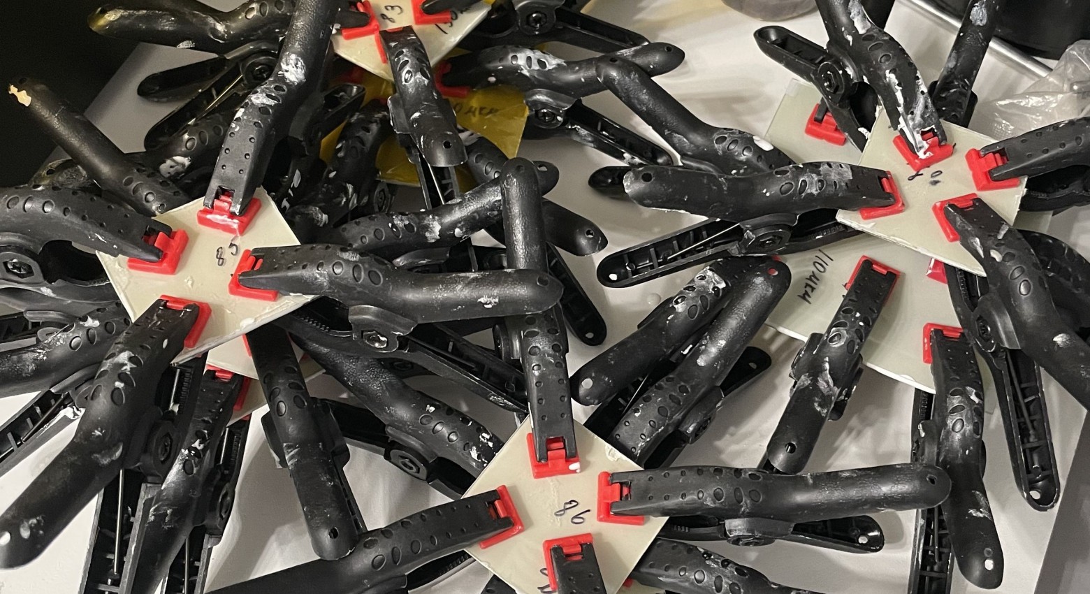
4Step 4: Glue the packet
Mix the BaTiO in two-componentepoxy resin in a ratio of 1: 1 and glue the packet with this composition and apply some pressure
![]()
-
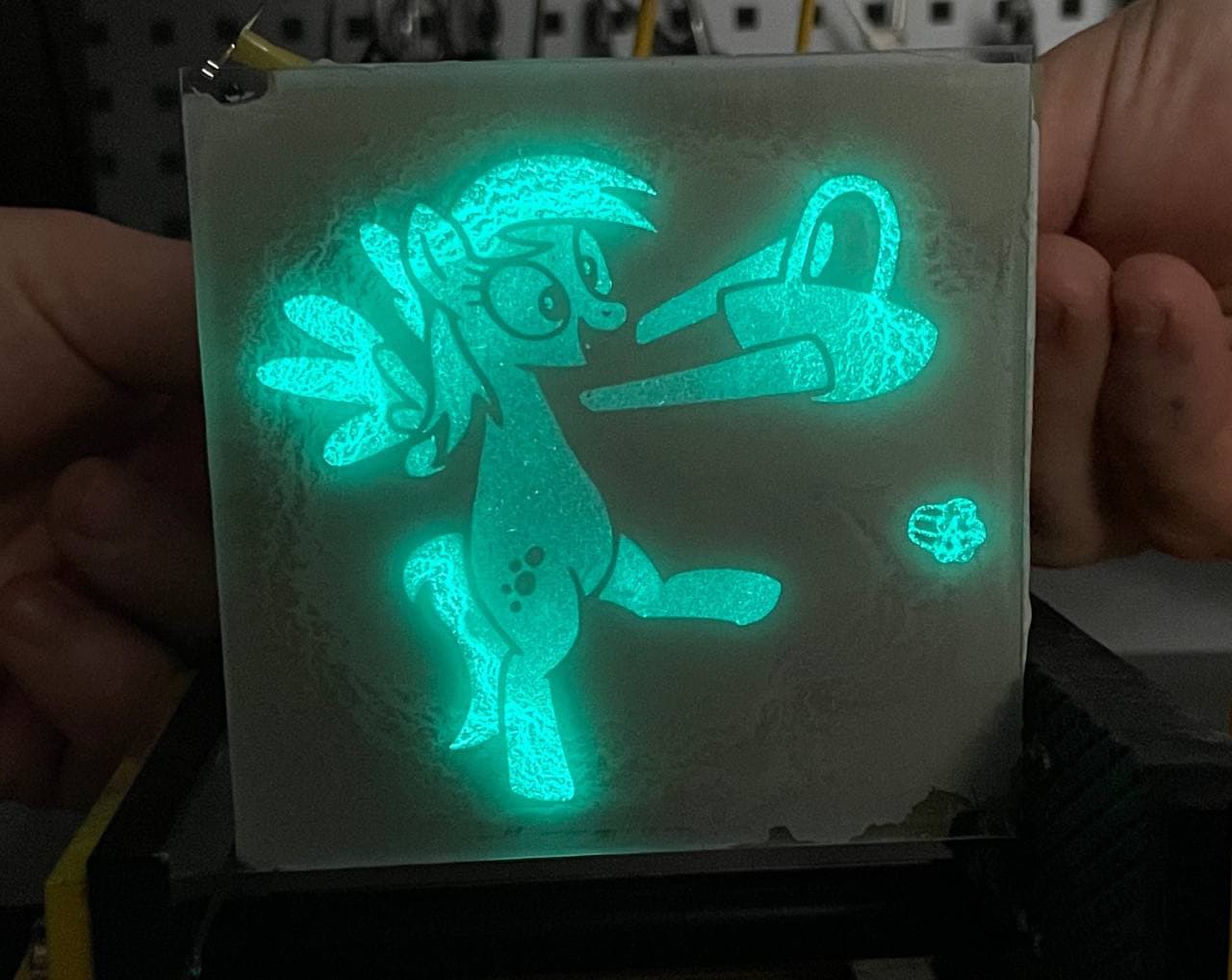
5Step 5: Connect EL panel to AC power supply
New EL panel require 100-300V 400-1200Hz
![]()
Self-made EL segment displays
How to make your own display with almost any configuration just using a paintbrush
Discussions
Become a Hackaday.io Member
Create an account to leave a comment. Already have an account? Log In.
Where did you order the phosphor?
Are you sure? yes | no