 Javier
-
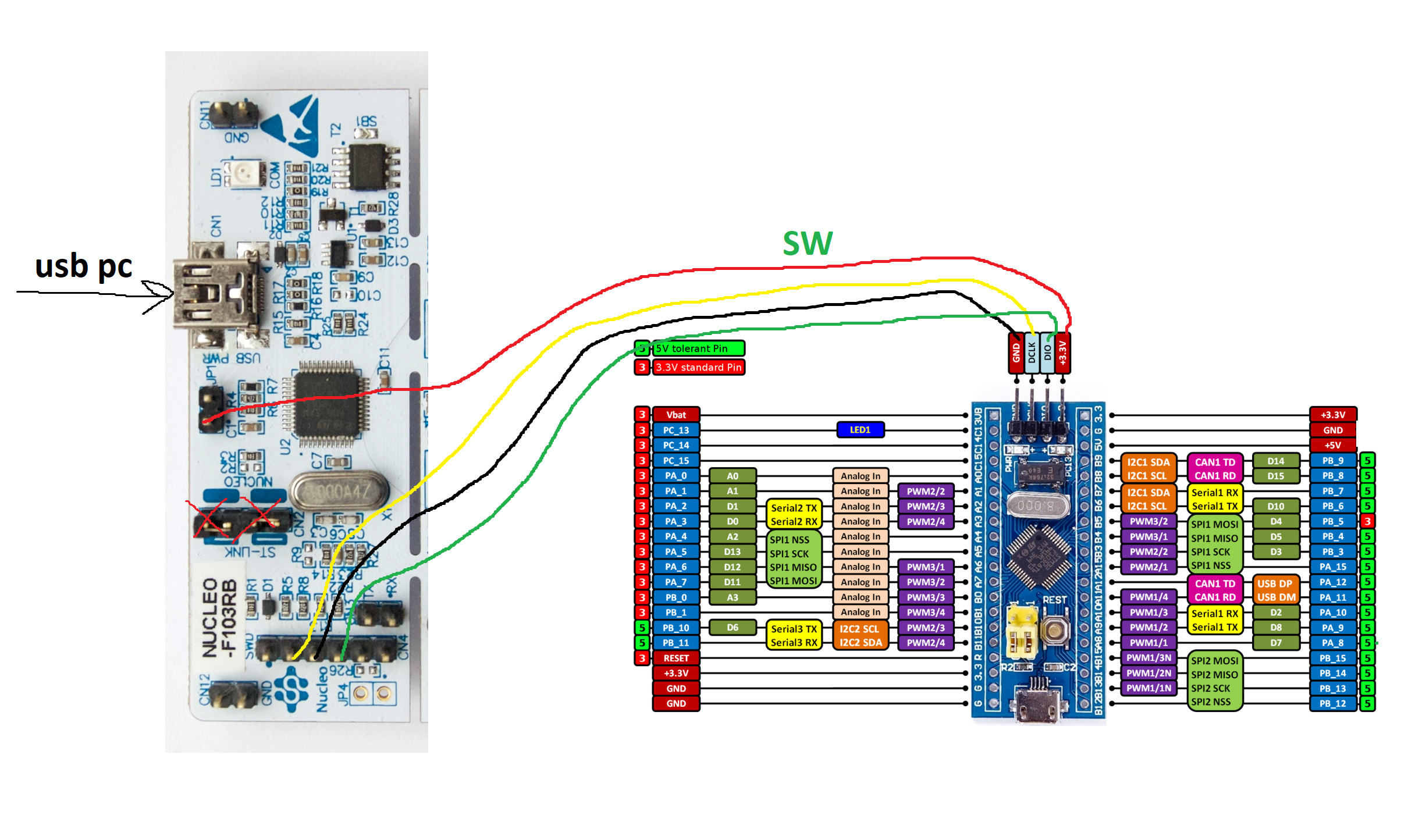
1Programming: hijacking a stlink
If we remove those two jumpers, our embedded stlink's SWclock and SWDIO lines are available for us to programm standalone boards like the bluepill, no extra bootloader needed except the one from ST.
![]()
-
2Configuration , autogenerating boiler plate code with CUBEMX
- First I set all GPIOA, B, C pins as outputs (and the Software SW debugging pins)
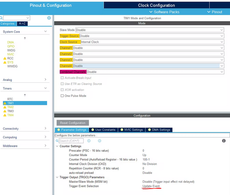
I tested HSI and HSE clocks, im going for the 8Mhz xtal clock source because allows me to run the micro at 72Mhz(trough PLL) - Now we find out which timers have a DMA channel with the option of being
triggered by Update event.TIM1, 2, 4 are good candidates
![]()
![]()
- First I set all GPIOA, B, C pins as outputs (and the Software SW debugging pins)
-
3Firmware: explaining the architecture a bit
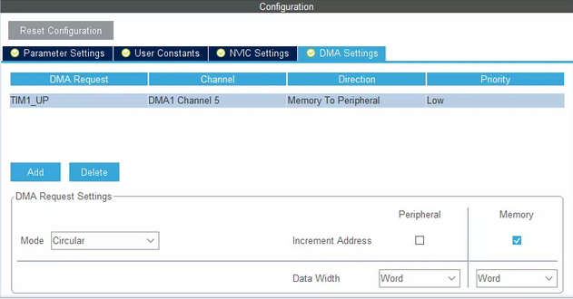
- In our case, the DMA will access a circular buffer in sram memory and move a word of data (4 bytes) to the corresponding GPIO peripheral.
The DMAs will run trough the buffers copying each uint32_t in its corresponding GPIOx->BSRR effectively changing every gpio ouput.
//I want my PWM to have 100 different duty steps, so i need a sram buffer those duty steps long. /* USER CODE BEGIN PV */ uint32_t dataA[lengthSoftPWMbuffer]; uint32_t dataB[lengthSoftPWMbuffer]; uint32_t dataC[lengthSoftPWMbuffer]; /* USER CODE END PV */- At the same time we could use this function to set our softPWM duty.
Remember this works by setting a gpio pin (writting in the lower 16bits of the BSRR) or reseting a gpio pin (writting in the upper 16bits of the BSRR)void setSoftPWM(uint16_t pin, uint32_t duty ,uint32_t *softpwmbuffer){ for (uint32_t i = 0; i < lengthSoftPWMbuffer; ++ i) { if(i<duty){//set pin softpwmbuffer[i]&=(uint32_t)~(pin<<16); softpwmbuffer[i]|=(uint32_t)pin; }else{//reset pin softpwmbuffer[i]&=(uint32_t)~(pin); softpwmbuffer[i]|=(uint32_t)pin<<16; } } }
- Now we start all the peripherals
/* USER CODE BEGIN 2 */
  //start the timers
HAL_TIM_Base_Start(&htim1);
HAL_TIM_Base_Start(&htim2);
HAL_TIM_Base_Start(&htim4);

//configure DMAs
HAL_DMA_Start(&hdma_tim1_up,     (uint32_t)&(dataA[0]), (uint32_t)&(GPIOA->BSRR), sizeof(dataA)/sizeof(dataA[0]));
HAL_DMA_Start(&hdma_tim2_up,     (uint32_t)&(dataB[0]), (uint32_t)&(GPIOB->BSRR), sizeof(dataB)/sizeof(dataB[0]));
HAL_DMA_Start(&hdma_tim4_up,     (uint32_t)&(dataC[0]), (uint32_t)&(GPIOC->BSRR), sizeof(dataC)/sizeof(dataC[0]));

//start DMAs
__HAL_TIM_ENABLE_DMA(&htim1, TIM_DMA_UPDATE);
__HAL_TIM_ENABLE_DMA(&htim2, TIM_DMA_UPDATE);
__HAL_TIM_ENABLE_DMA(&htim4, TIM_DMA_UPDATE);

//ill use o as a main variable for this tutorial
uint32_t o=0;
//im afraid of SRAMs not being initialised to 0
- To set a specific pwm value we use:
Pin is the gpio pin index inside the GPIO
bankDuty is the 0-100 dutycycle to be set.
softpwmbuffer is the pointer to the array storing all the BSRR values.setSoftPWM(GPIO_PIN_9, o, &dataA);
- In our case, the DMA will access a circular buffer in sram memory and move a word of data (4 bytes) to the corresponding GPIO peripheral.
-
4Firmware: implementation
if we want to use the 33 pins available and create a wavy dimm:
/* USER CODE BEGIN 3 */
      //GPIO bank A
      setSoftPWM(GPIO_PIN_0, o, (uint32_t*)&dataA);
      setSoftPWM(GPIO_PIN_1, o, (uint32_t*)&dataA);
      setSoftPWM(GPIO_PIN_2, o, (uint32_t*)&dataA);
      setSoftPWM(GPIO_PIN_3, o, (uint32_t*)&dataA);
      setSoftPWM(GPIO_PIN_4, o, (uint32_t*)&dataA);
      setSoftPWM(GPIO_PIN_5, o, (uint32_t*)&dataA);
      setSoftPWM(GPIO_PIN_6, o, (uint32_t*)&dataA);
      setSoftPWM(GPIO_PIN_7, o, (uint32_t*)&dataA);
      setSoftPWM(GPIO_PIN_8, o, (uint32_t*)&dataA);
      setSoftPWM(GPIO_PIN_9, o, (uint32_t*)&dataA);
      setSoftPWM(GPIO_PIN_10, o, (uint32_t*)&dataA);
      setSoftPWM(GPIO_PIN_11, o, (uint32_t*)&dataA);
      setSoftPWM(GPIO_PIN_12, o, (uint32_t*)&dataA);
      setSoftPWM(GPIO_PIN_15, o, (uint32_t*)&dataA);
      //GPIO bank B
      setSoftPWM(GPIO_PIN_0, o, (uint32_t*)&dataB);
      setSoftPWM(GPIO_PIN_1, o, (uint32_t*)&dataB);
      setSoftPWM(GPIO_PIN_2, o, (uint32_t*)&dataB);
      setSoftPWM(GPIO_PIN_3, o, (uint32_t*)&dataB);
      setSoftPWM(GPIO_PIN_4, o, (uint32_t*)&dataB);
      setSoftPWM(GPIO_PIN_5, o, (uint32_t*)&dataB);
      setSoftPWM(GPIO_PIN_6, o, (uint32_t*)&dataB);
      setSoftPWM(GPIO_PIN_7, o, (uint32_t*)&dataB);
      setSoftPWM(GPIO_PIN_8, o, (uint32_t*)&dataB);
      setSoftPWM(GPIO_PIN_9, o, (uint32_t*)&dataB);
      setSoftPWM(GPIO_PIN_10, o, (uint32_t*)&dataB);
      setSoftPWM(GPIO_PIN_11, o, (uint32_t*)&dataB);
      setSoftPWM(GPIO_PIN_12, o, (uint32_t*)&dataB);
      setSoftPWM(GPIO_PIN_13, o, (uint32_t*)&dataB);
      setSoftPWM(GPIO_PIN_14, o, (uint32_t*)&dataB);
      setSoftPWM(GPIO_PIN_15, o, (uint32_t*)&dataB);
      //GPIO bank C
      setSoftPWM(GPIO_PIN_13, o, (uint32_t*)&dataC);
      setSoftPWM(GPIO_PIN_14, o, (uint32_t*)&dataC);
      setSoftPWM(GPIO_PIN_15, o, (uint32_t*)&dataC);

      //thats it 33 PWM pins looping 0-100 duty cycle yeeey
      o++;
      if(o>100){
          o=0;
      }
  }
  /* USER CODE END 3 */
I tested with different Clock and timer speeds, I could generate up to a 47kHZ pwm with 100 steps before I see a bit of jitter.
All pins are PWM now , all at once (STM32)
Baremetal SoftPWM, DMA reading buffers and seting GPIOs
Discussions
Become a Hackaday.io Member
Create an account to leave a comment. Already have an account? Log In.