If we remove those two jumpers, our embedded stlink's SWclock and SWDIO lines are available for us to programm standalone boards like the bluepill, no extra bootloader needed except the one from ST.
2
Testing functionalities, led blink
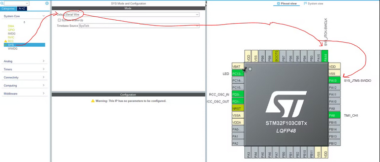
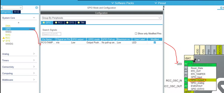
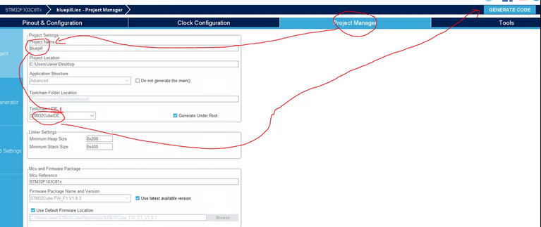
Blinky minimum system test: Lets setup the bluepill board, im going to use the SerialWire port, the external 8Mhz cristal and the PC13 LED for now.
setting up the SW port
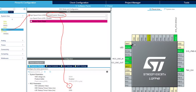
setting up the external XTAL
setting up the pwm output
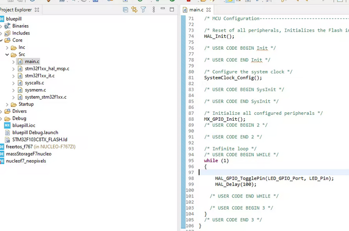
With this minimal setup I generate the code and proceed to do a simple PC13 blinky program.
//you can find User defined pin names in main.h
HAL_GPIO_TogglePin(LED_GPIO_Port, LED_Pin);
HAL_Delay(100);
generating with cubeMX
voilá, our pc13 led is blinking
3
Testing functionalities, pwm
okay the bluepill is alive now we need to start calculating clocks and shit.
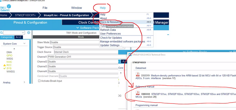
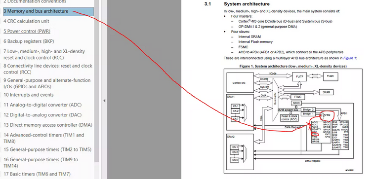
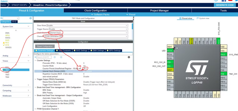
First we need to choose the PWM timer, I chose TIM1.Now we figure out which clock is feeding TIM1, sadly we need to read the family specific reference manual
CubeMX link to latest reference manual.
RM0008 ref manual.
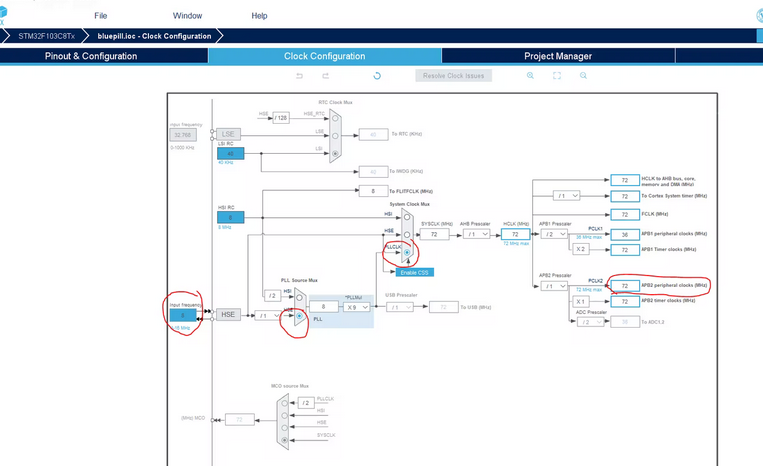
It turns out TIM1 is fed with APB2 clock, so I set the clock source to be taken from the external 8Mhz xtal trough the PLL (more stable and precise than the internal HSI RC) and adjust the APB2 timer clock source as i need.
I am choosing 72Mhz because is the maximum clock speed ,this way we will get less granularity errors.
if we have a 72Mhz pwm and we want a 0, 8Mhz pwm we need a 72/0, 8=90 preescaler
90=90-1 (register stuff)
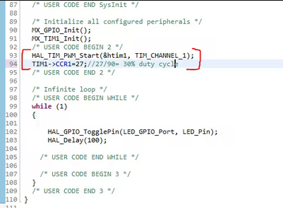
ini tim1 channel and set duty to 30%
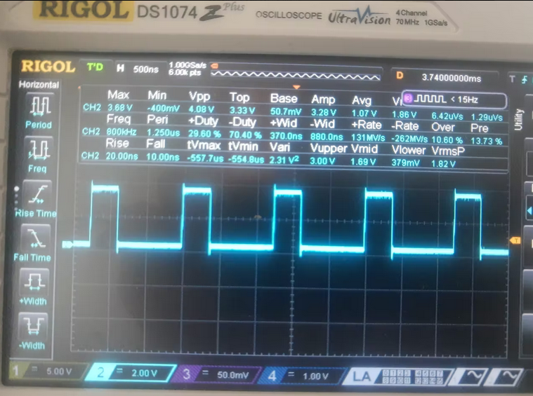
result
/* USER CODE BEGIN 2 */
HAL_TIM_PWM_Start(&htim1, TIM_CHANNEL_1);
TIM1->CCR1=27;//27/90= 30% duty cycle
/* USER CODE END 2 */
4
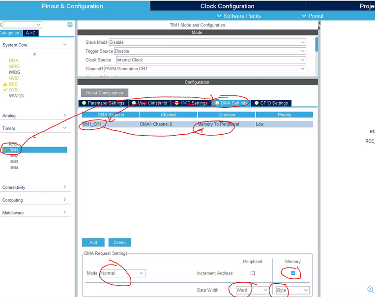
Testing functionalities, DMA+pwm
things are starting to get serious now. We use the DMA to "load" the PWM value (TIM1->CCR1) automatically from a list of values stored in memory, once we give the order, the DMA will update TIM1->CCR1 every time there is a TIM1 update event(every pwm cycle). This is all handled by the DMA+PWM so our Core only starts the DMA transaction and from there DMA bursts the databuffer out trough pwm one time (DMA normal mode).
Edit: some MCUs (like stm32f407vg) dont have the Byte option in the DMA configuration, it forces us to use word (uint32_t) sizes for our <em>dataToPwm</em> array.(hey.... as long as we have enough SRAM....)
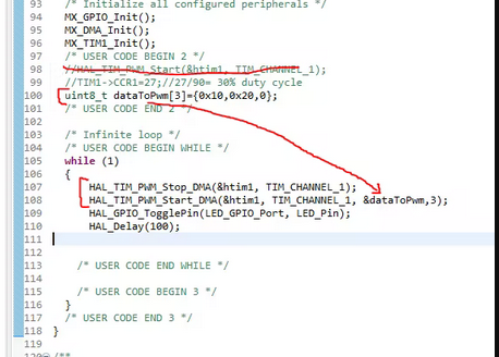
This code blinks the onboard led and triggers the DMA conversion to spit out dataToPwm values to be loaded in TIM1->CCR1, every 10 ms.
This is of no use to us yet, only for testing
/* USER CODE BEGIN 2 */  //HAL_TIM_PWM_Start(&htim1, TIM_CHANNEL_1);//we dont need this now, dma is in charge  //TIM1->CCR1=27;//27/90= 30% duty cycle    //we dont need this now, dma is in charge  uint8_t dataToPwm[3]={0x10,0x20,0};//needs to end in 0 to silence the pwm  /* USER CODE END 2 */
  /* Infinite loop */  /* USER CODE BEGIN WHILE */  while (1)  {
      HAL_TIM_PWM_Stop_DMA(&htim1, TIM_CHANNEL_1);
      HAL_TIM_PWM_Start_DMA(&htim1, TIM_CHANNEL_1, &dataToPwm,3);
      HAL_GPIO_TogglePin(LED_GPIO_Port, LED_Pin);
      HAL_Delay(10);

    /* USER CODE END WHILE */
    /* USER CODE BEGIN 3 */  }
5
Firmware: implementation
By now we should have initialiced and correctly configured our DMA and TIM1 PWM channel 1
We need to define first:
#define numberofpixels 3#define bytesperpixel 3//https://cdn-shop.adafruit.com/datasheets/WS2812.pdf//neopixel understands a bit as high when it sees a pwm with 64% duty cycle#define bitHightimercount 90*0.64 //if our pwm period is 90, 64%(90)=57.6 close to 58//neopixel understands a bit as low when it sees a pwm with 32% duty cycle#define bitLowtimercount 90*0.32 //if our pwm period is 90, 32%(90)=28.8 close to 29
We also need our buffer, where all rgb values for every pixel are stored
//we need 3 neopixel colours (r g b) thats 3 neopixel bytes for every pixel.
//we need 8 PWM cycles to transmit 1 neopixel byte.
//we need 1 uint8_t(or /uint16_t/uint32_t in other boards) to be loaded in TIM1->CCR1 for every PWM cycle.
uint8_t rgbw_arr[numberofpixels * bytesperpixel * 8 + 1];//every pixel colour info is24 bytes long
We arrived to the functions, we need a flush function as I defined rgbw_arr to be stored in RAM and it could be full of trash
voidflushArrayPixel(//zeroes the arrayuint8_t *buffer, //address of our bufferuint8_t bytenumber //number of bytes to erase
){
for (uint32_t i = 0; i < bytenumber-1; ++i) {
buffer[i] = bitLowtimercount;
}
buffer[bytenumber] = 0;//needs to be 0 to silent PWM at the end of transaction
}
This is the magic function, it loads the buffer one pixel at a time (shitty page formatting hackster....)
uint32_t loadArrayOnePixel(uint8_t R, uint8_t G, uint8_t B,
uint8_t *buffer, //address of our bufferuint8_t pixelnumber //pixel index inside buffer
) {
if(pixelnumber>numberofpixels){return-1;}//in case we mess upfor (uint32_t i = 0; i < bytesperpixel * 8; ++i) { //we need to store every bitif (i < 8) { //this means first byte Rif (R & (0x80 >> i)) { //this is a mask for reading every bit inside the byte R
buffer[i + pixelnumber * bytesperpixel * 8] = bitHightimercount;
} else {
buffer[i + pixelnumber * bytesperpixel * 8] = bitLowtimercount;
}
}
if ((i >= 8) & (i < 16)) { //this means second byte Gif (G & (0x80 >> (i - 8))) {
buffer[i + pixelnumber * bytesperpixel * 8] = bitHightimercount;
} else {
buffer[i + pixelnumber * bytesperpixel * 8] = bitLowtimercount;
}
}
if ((i >= 16) & (i < 24)) { //this means third byte Bif (B & (0x80 >> (i - 16))) {
buffer[i + pixelnumber * bytesperpixel * 8] = bitHightimercount;
} else {
buffer[i + pixelnumber * bytesperpixel * 8] = bitLowtimercount;
}
}
}
return1;
}
Now we just use everything in our main, small relaxing blue dimming
/* USER CODE BEGIN 2 *///flush buffer first
flushArrayPixel(&rgbw_arr, sizeof(rgbw_arr)/sizeof(rgbw_arr[0]));
//for led effectuint8_t counter=0;
uint8_t flag=0;
/* USER CODE END 2 *//* Infinite loop *//* USER CODE BEGIN WHILE */while (1) {
//dont know why exactly yet but DMA needs to be stopped before trigger it again
HAL_TIM_PWM_Stop_DMA(&htim1, TIM_CHANNEL_1);
/////////////////////////////////////////////////////blue soft pulse of every pixelfor (uint32_t i = 0; i < numberofpixels; ++i) {
loadArrayOnePixel(0,0,counter,&rgbw_arr,i);
}
HAL_TIM_PWM_Start_DMA(&htim1, TIM_CHANNEL_1, &rgbw_arr,sizeof(rgbw_arr)/sizeof(rgbw_arr[0]));
if(counter==0xFF){flag=0;}
if(counter==0x00){flag=1;}
if(flag){
counter++;
}else{
counter--;
}
/////////////////////////////////////////////////////
HAL_GPIO_TogglePin(LED_GPIO_Port, LED_Pin);
HAL_Delay(10);
/* USER CODE END WHILE *//* USER CODE BEGIN 3 */
}
 Javier
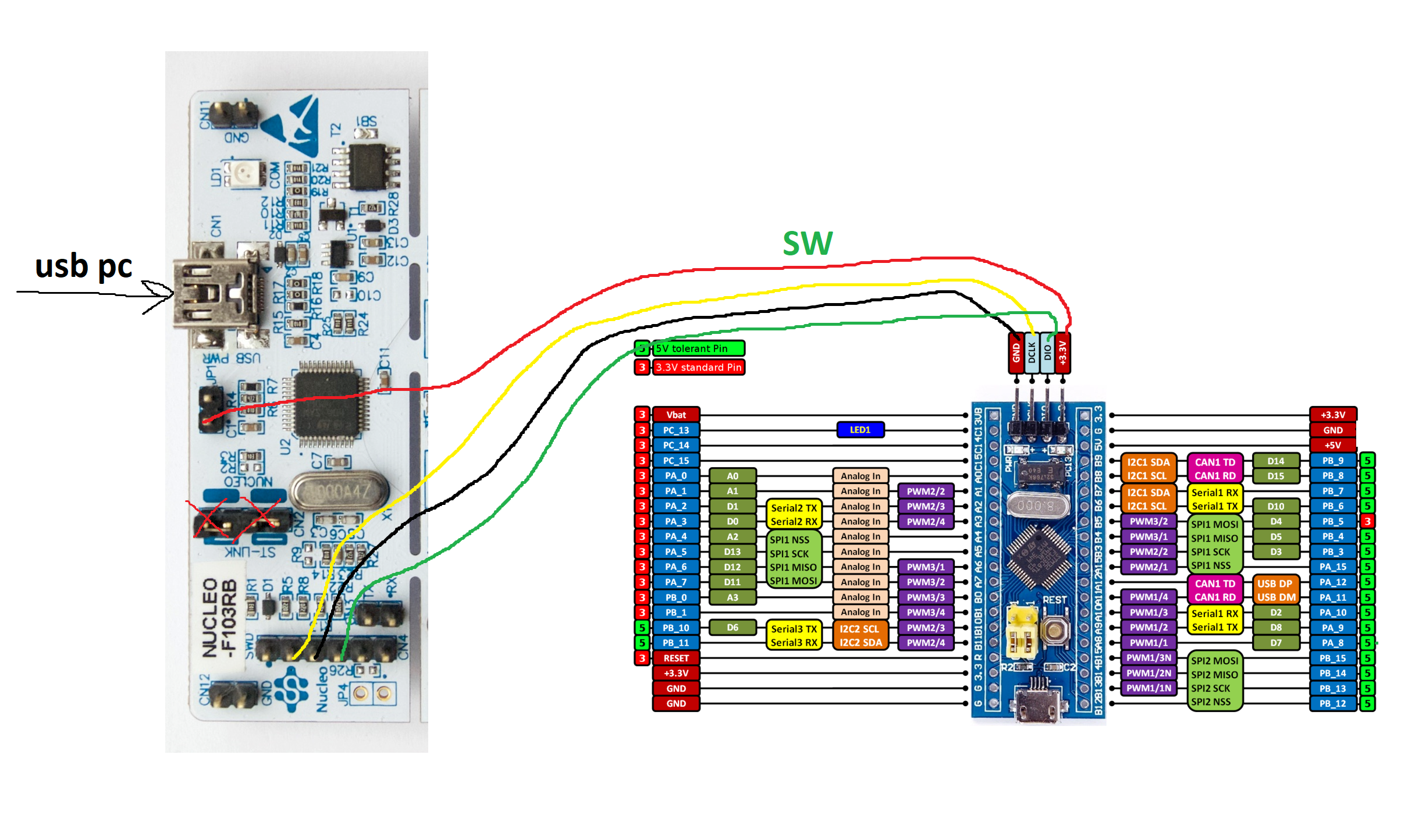

Discussions
Become a Hackaday.io Member
Create an account to leave a comment. Already have an account? Log In.