0%
0%
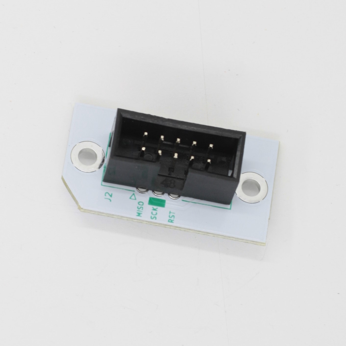
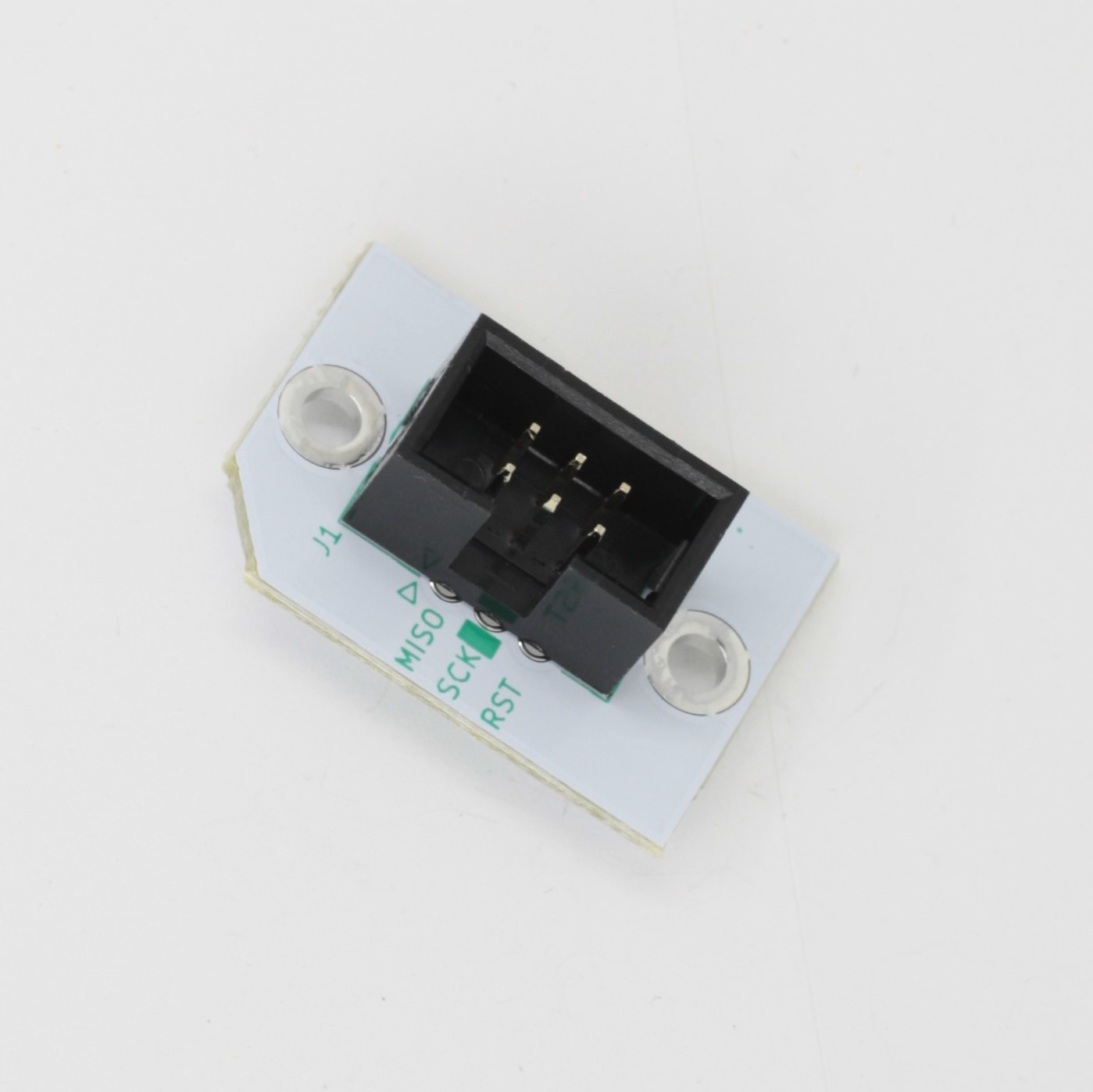
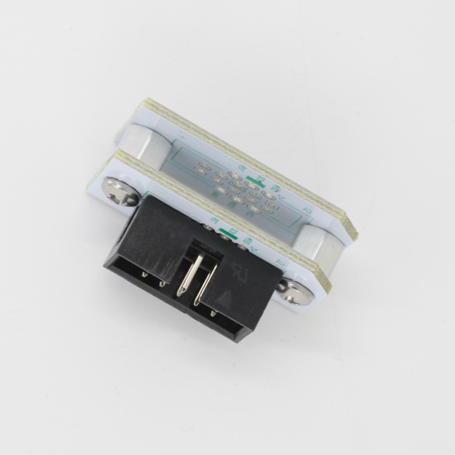
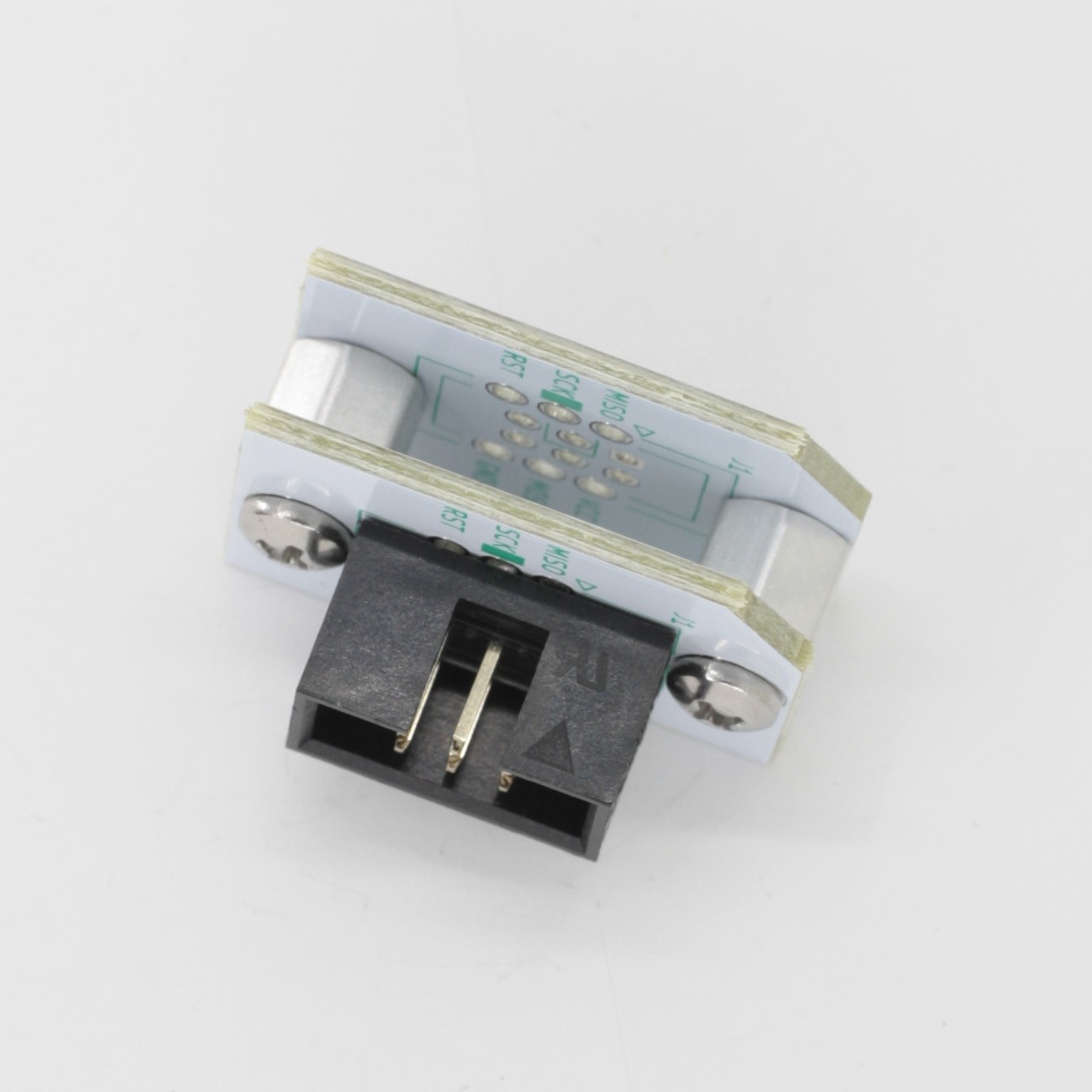
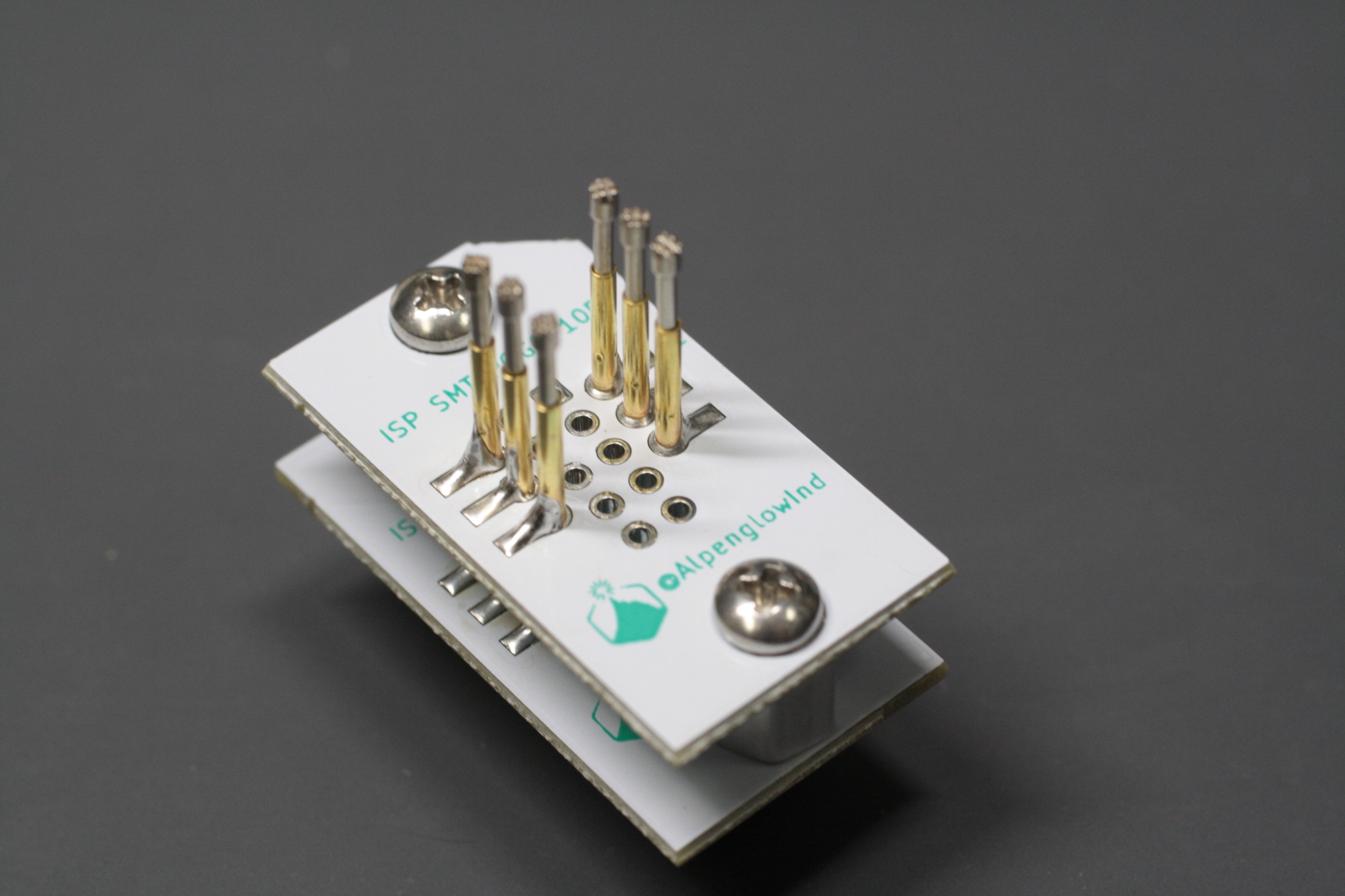
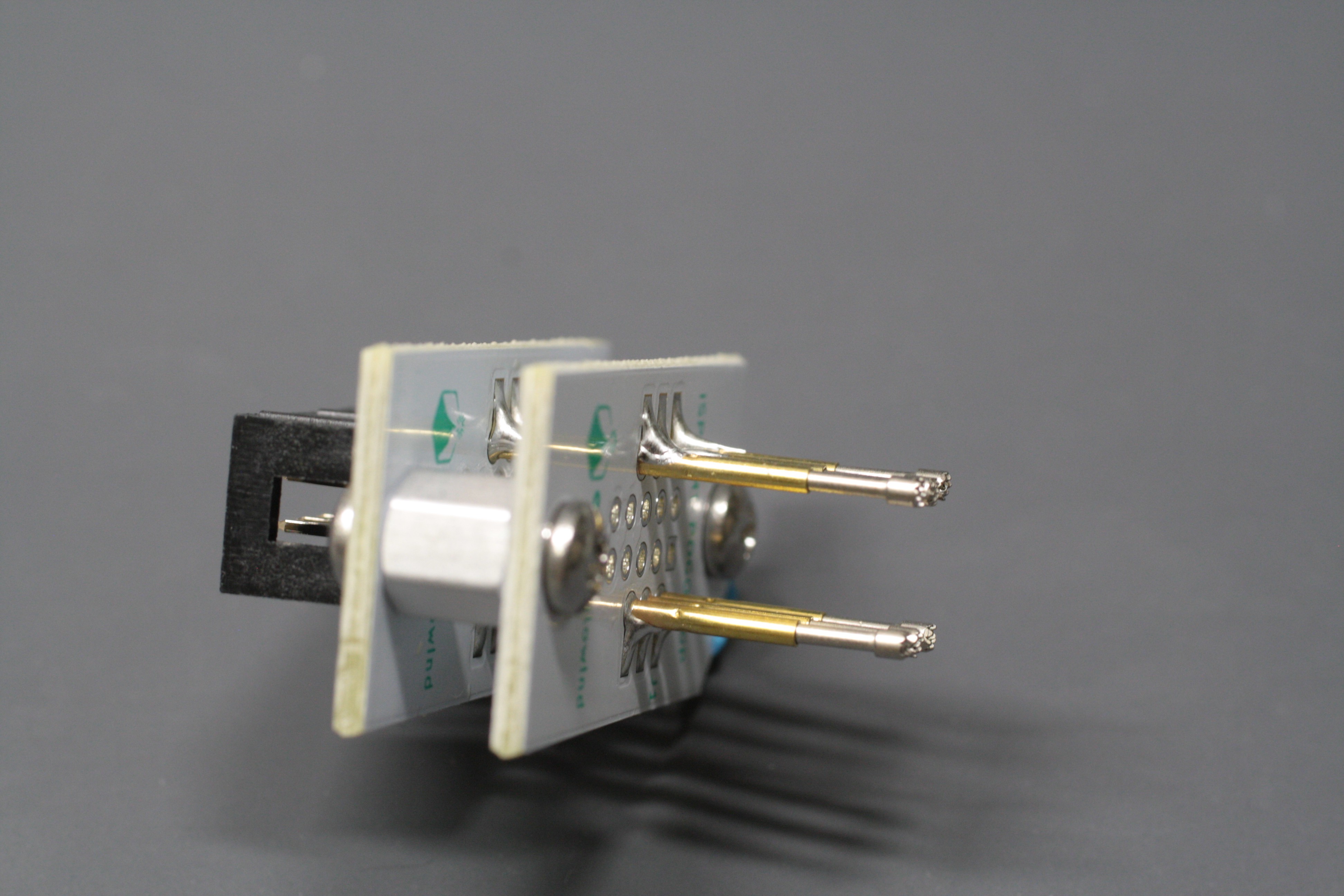
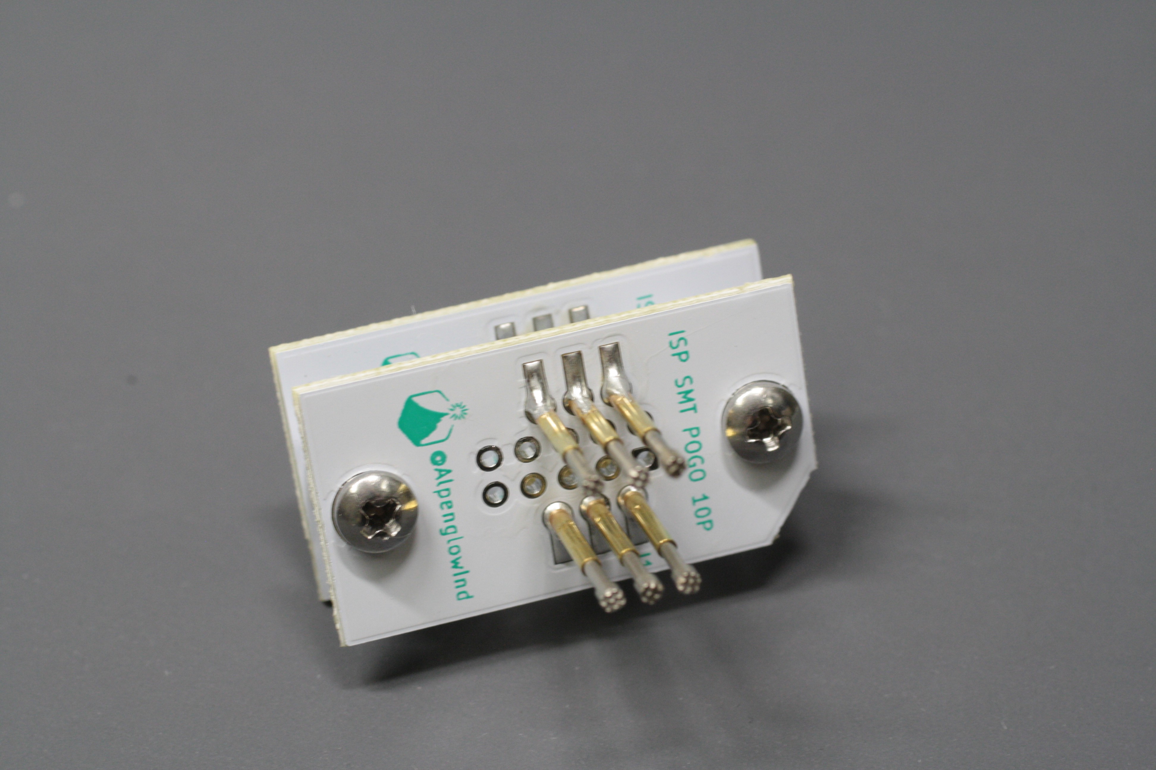
ISP Pogo Adapters
Instructions for how to assemble your ISP Pogo adapter for both the 6-pin and the 10-pin connector.
 Alpenglow Industries
Become a Hackaday.io member
Already have an account? Log in.
Just one more thing
To make the experience fit your profile, pick a username and tell us what interests you.
Pick an awesome username
hackaday.io/
Your profile's URL: hackaday.io/username. Max 25 alphanumeric characters.
Pick a few interests
Projects that share your interests
People that share your interests
 DL101
DL101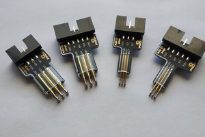
 Pnoxi
Pnoxi
 Vitaly Rudik