-
1Solder Top components
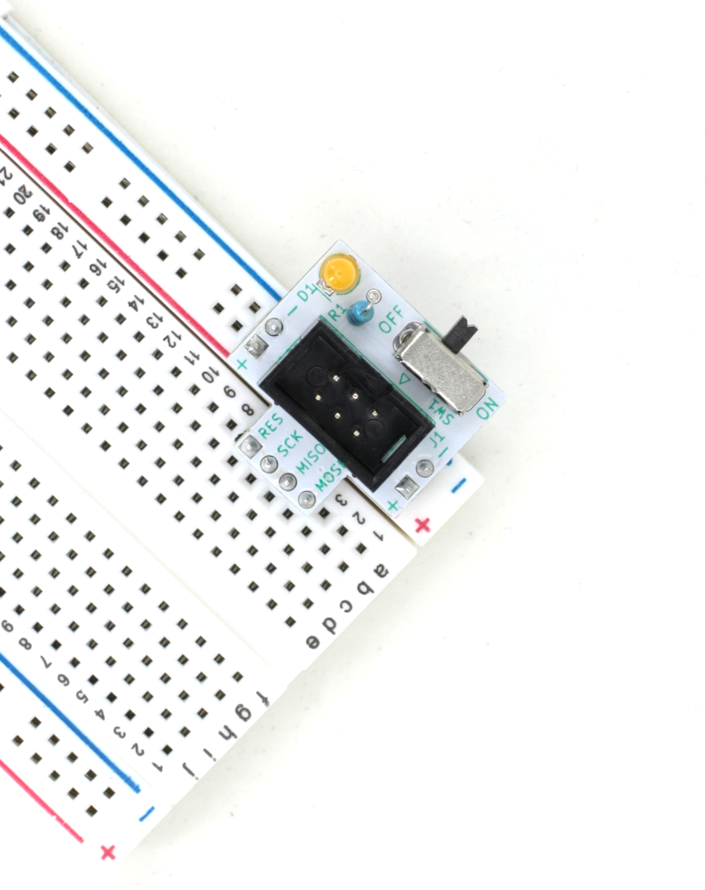
We like soldering the switch first, then the LED and resistor, then the 6-pin ISP connector.
![]()
-
2Solder Bottom Headers
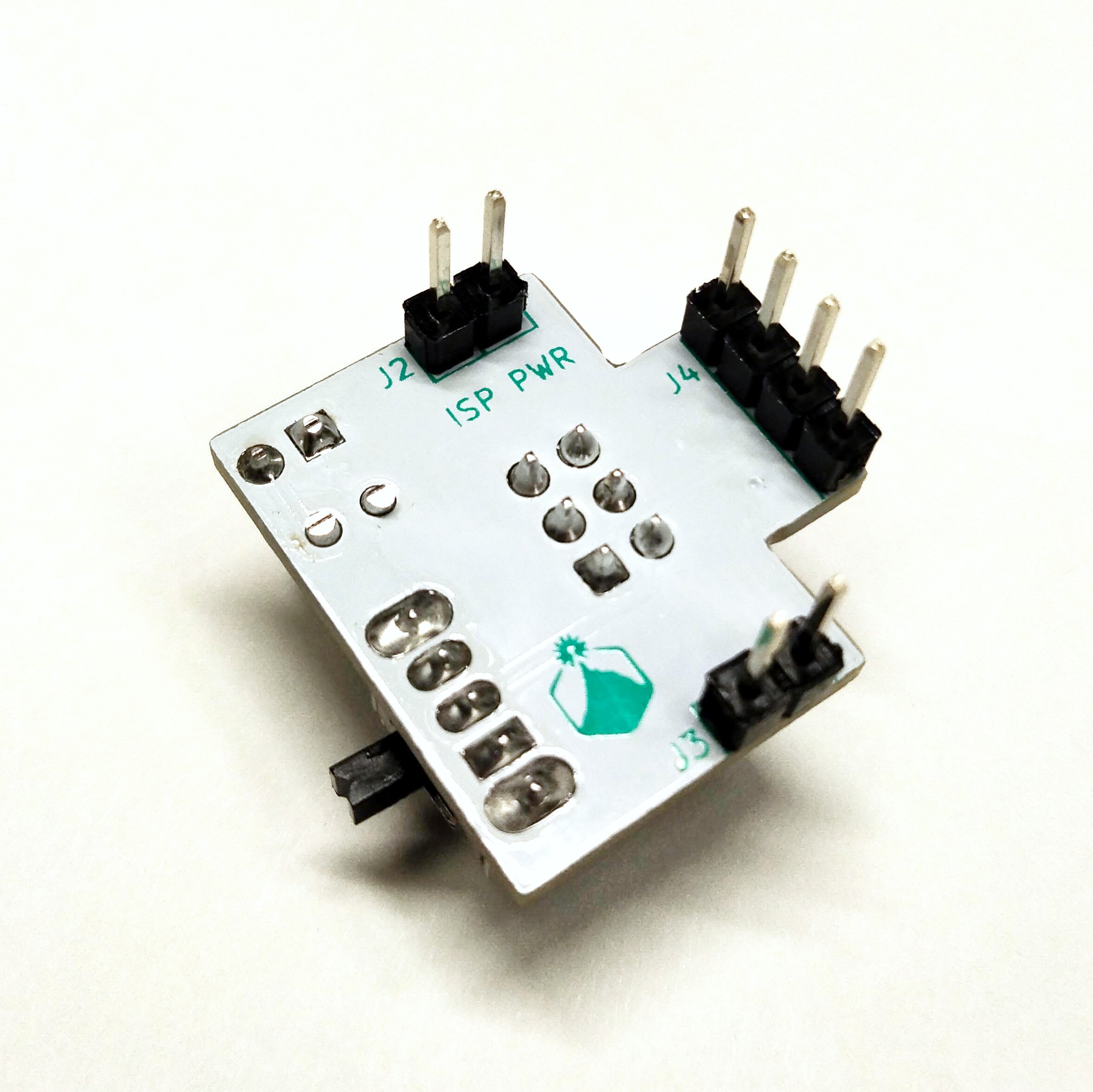
After that, you can use a breadboard as a jig by placing the remaining 4 headers that are on the bottom into the breadboard to hold them in place, drop the PCB over top of them, and then solder them in.
![]()
 Alpenglow Industries

Discussions
Become a Hackaday.io Member
Create an account to leave a comment. Already have an account? Log In.