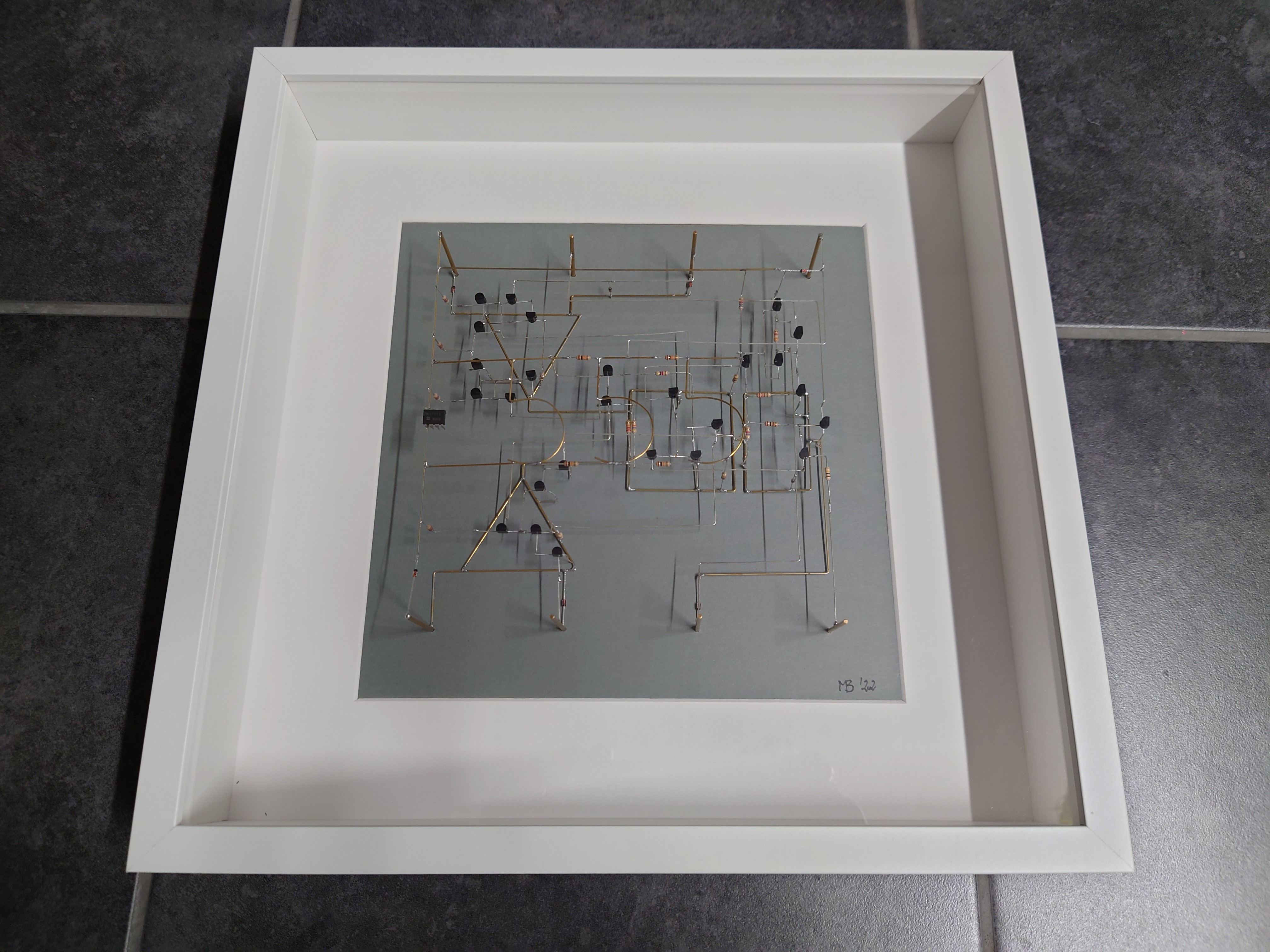
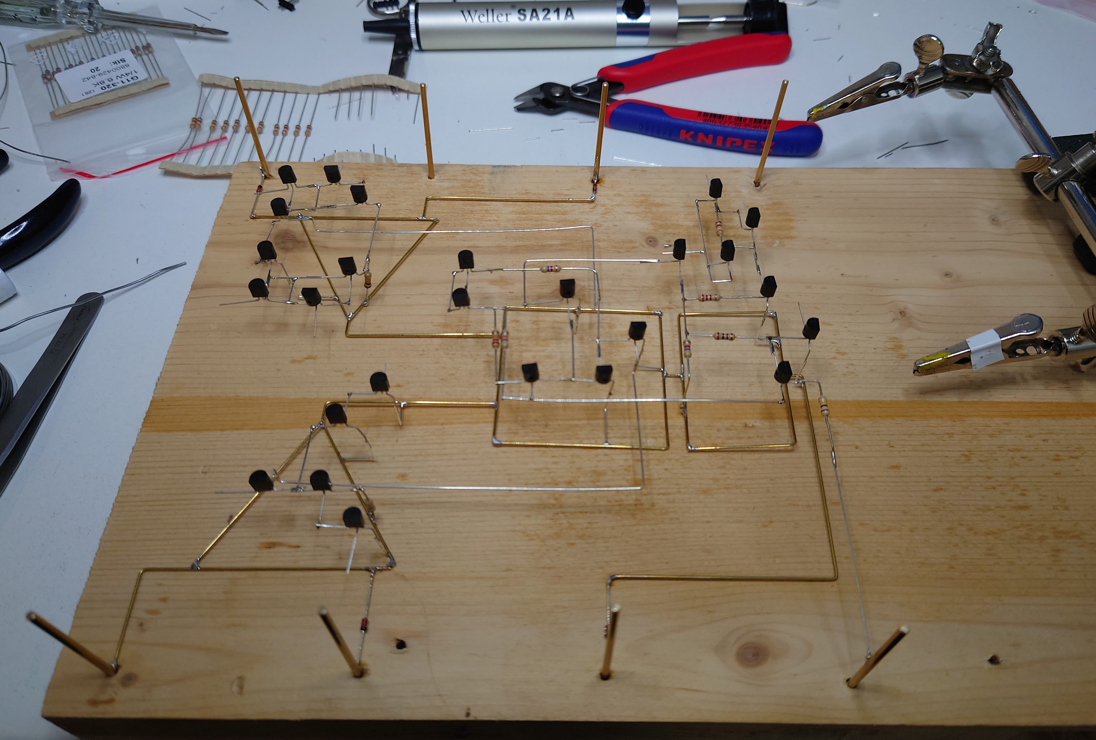
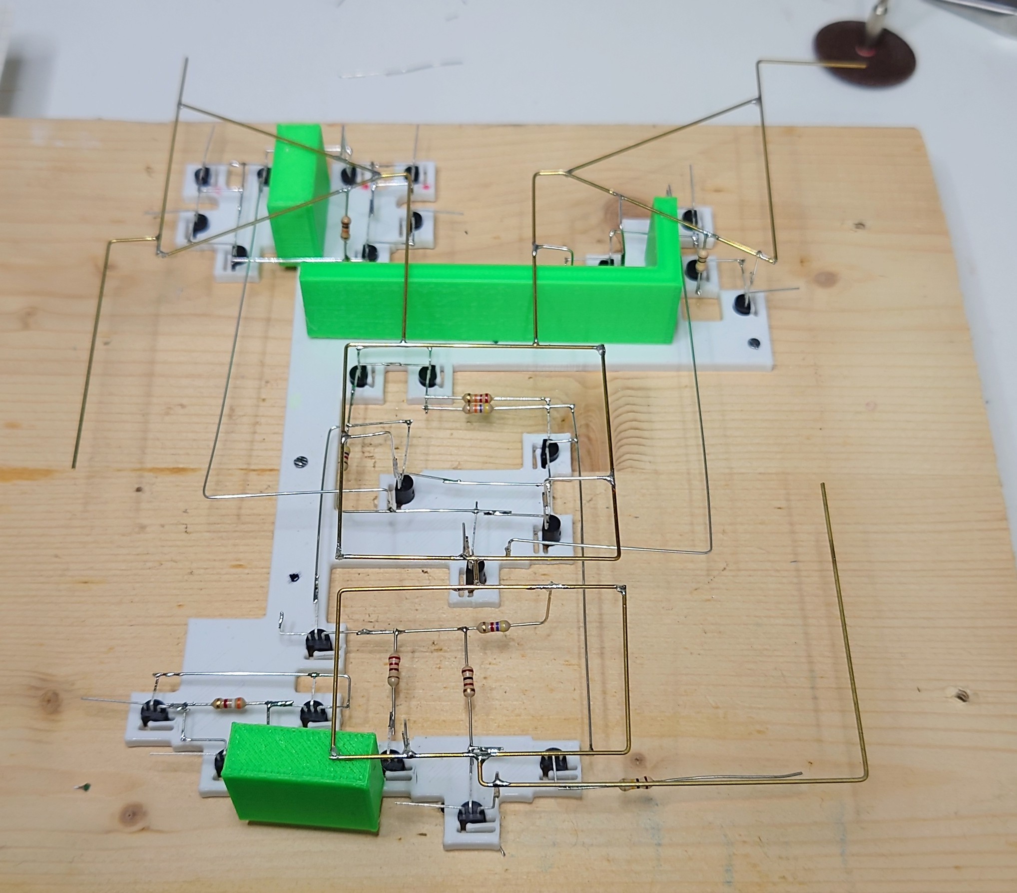
My design has basically three layers:
The ground plane (sic!) shows the (very schematic) block diagram using 0.8mm brass wire.
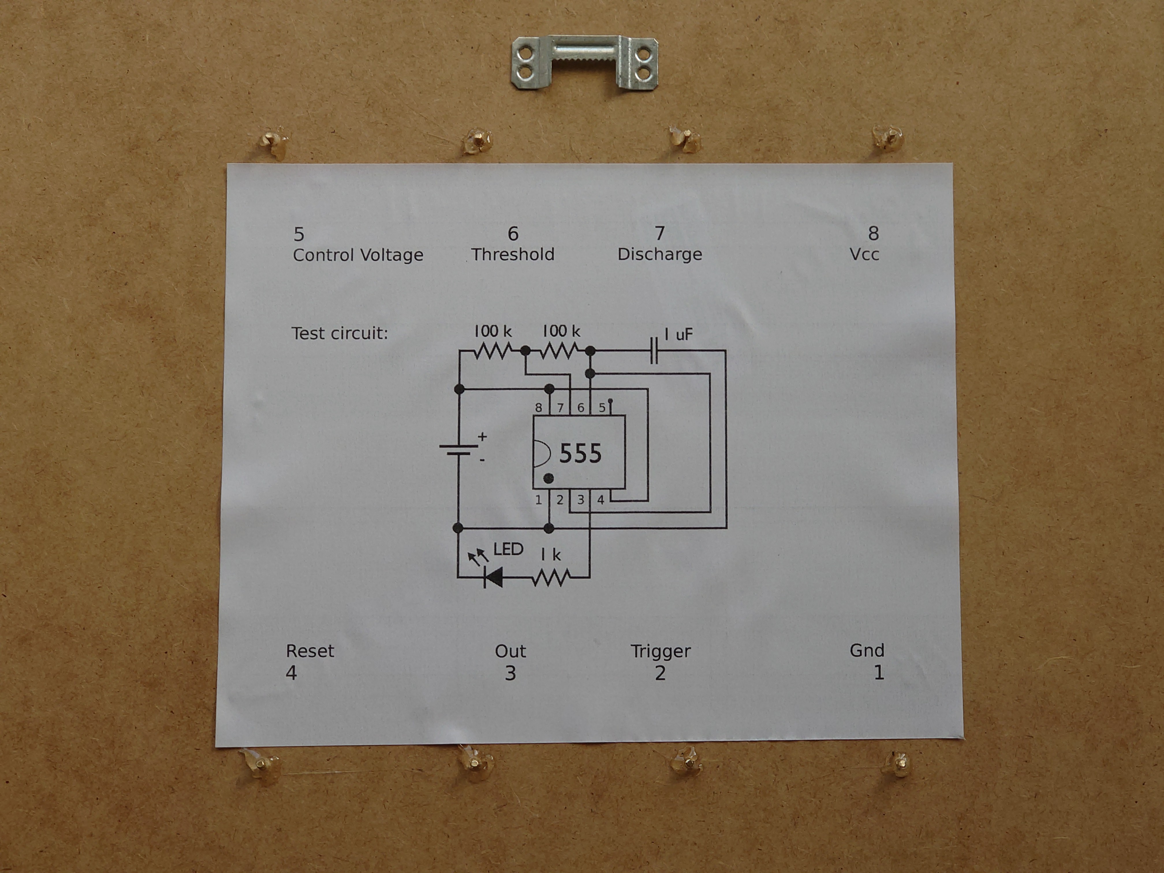
The top plane is the supply voltage. Again in 0.8mm brass wire. Additionally, the three 5s designating the circuit are there. Each of them on a different potential (Vcc, 2/3 Vcc and 1/3 Vcc). I implemented the triple 5k voltage divider using 10k resistors in parallel (more mechanical stability).
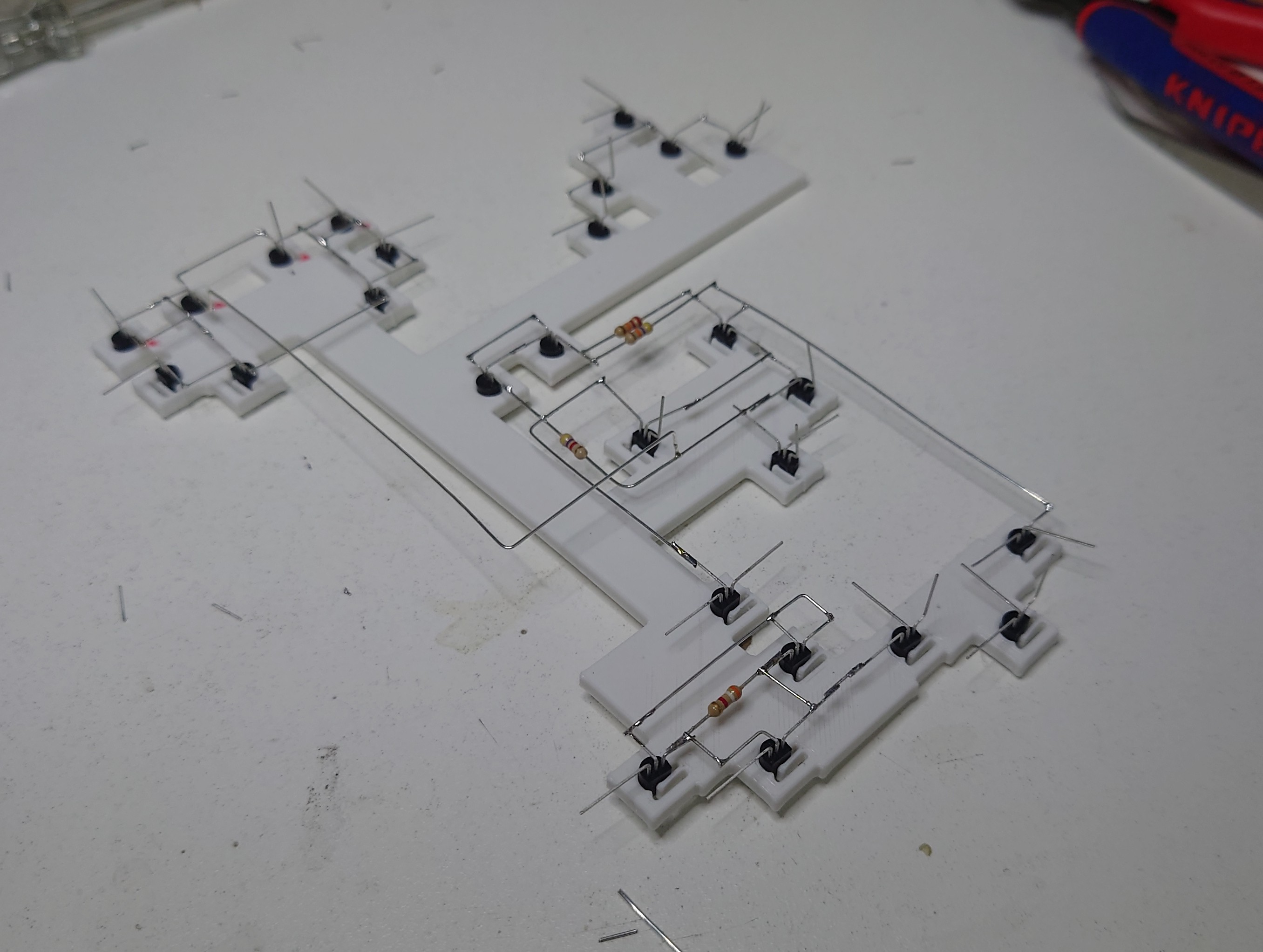
In between is the circuit comprising the 26 transistors and some resistors. Here I used silver plated copper wire (0.6 mm) to allow it to be distinguishable from the other two layers.
Instead of a notch in the IC housing to mark pin one I soldered a NE555 at the corresponding position.
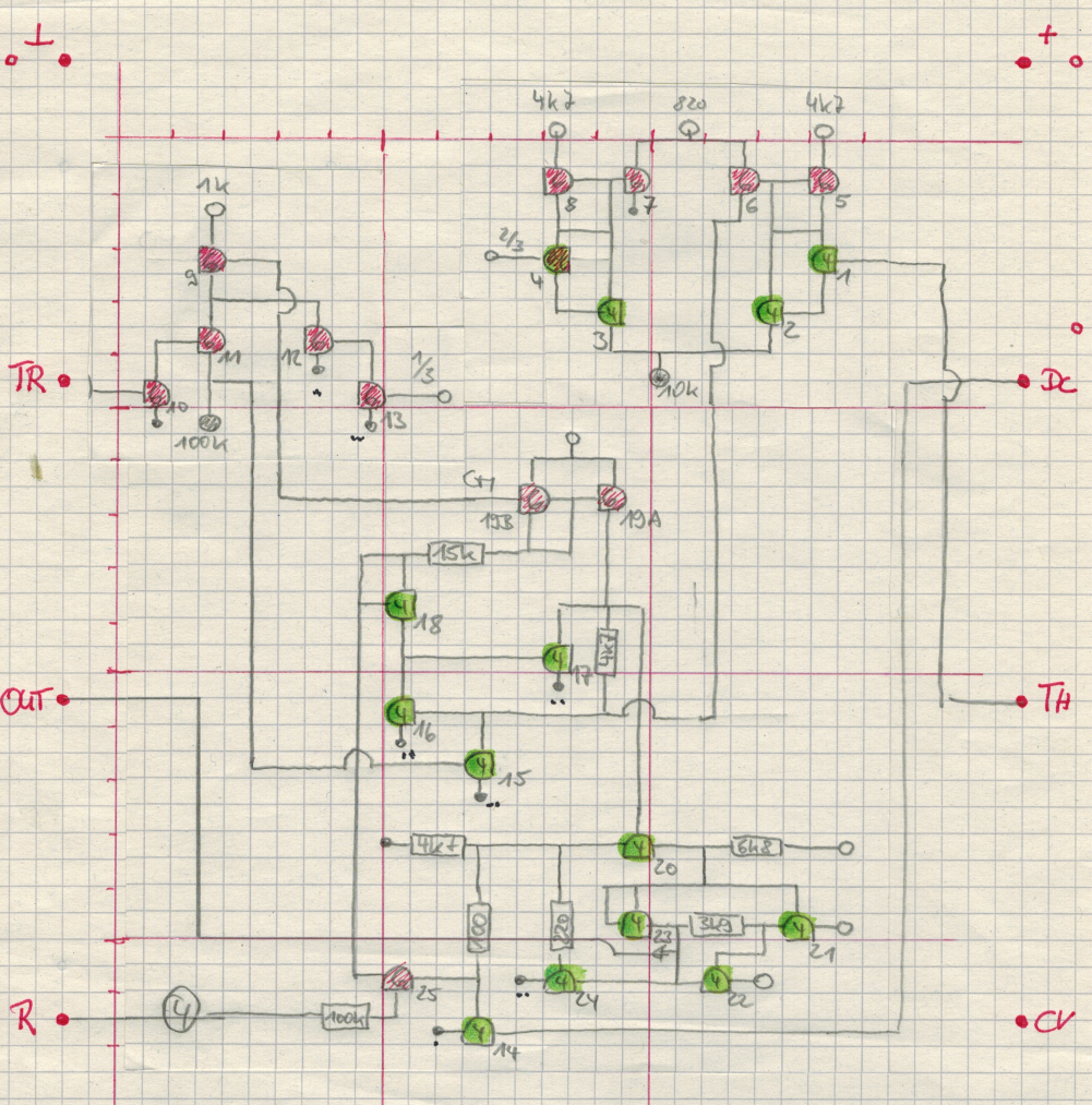
The circuit is the well-documented one (see https://cdn.evilmadscientist.com/KitInstrux/555/555_principles_rev30.pdf) and it's not based on my intellectual work. Therefore I do not provide neither the schematic nor a list of components. The attentive reader will note some additional 1N4148s to increase mechanical stability and that I used two resistors in parallel where I didn't have the correct value in my stock.
I see my part in the artistic way I implemented the circuit. Noting more, nothing less.
The overall size is 18 cm x 18 cm x 6 cm.
 MaBe42


 Discrete Electronics Guy
 Torbjörn Lindholm
 DIY GUY Chris
Very cool idea to work the block diagram into the circuit. Nice job!