 Jesse Farrell
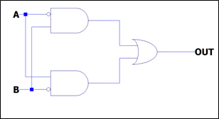
An XOR gate returns a 1 if a single input is high. If all inputs are high, then it returns a 0. The XOR gate may be implemented with 2x 555’s and an OR gate (seen below).
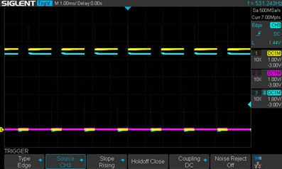
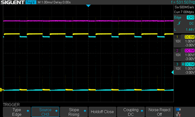
The breadboarded circuit worked as expected (albeit with the previously mentioned delay). Note there is some voltage drop at the output due to the diode OR circuit.
Yellow = input / Purple = input / Blue = output
Discussions
Become a Hackaday.io Member
Create an account to leave a comment. Already have an account? Log In.