For my goals I have the following setup in mind:
Microcontroller: ESP8266
https://hackerstore.nl/Artikel/1020
https://wiki.iteadstudio.com/PSF-A85
This is a unit I have worked with earlier. So I know how to set it up and program it.
I can upload firmware OTA (Over The Air). So I don't need any headers or wires exposed and it can remain in it's docking when I'm trying new stuff. This does mean I want to build a second prototyping setup where I can try out new software and check if the upload still works. This way I don't have to disassemble the Roomba every time my code breaks.
It will have a header for the first upload. This header will provide power, ground, connection to reset and program pins and 3.3V level Tx and Rx UART.
Power will come from the Roomba battery. I'm using a LM7833 linear voltage regulator to provide the 3.3V. I'm going to change this later (don't have the parts a.t.m.) because it has to dissipate quite some power. The battery level can get to 17V. The ESP8266 can draw 100mA. Normal operating conditions ~80mA. This means the LM7833 dissipates about (17V-3.3V)*0.1A=1.37W That's a bit much and absolutely unnecessary.
I've ordered a few Buck DC/DC step down converters. To provide the 3.3V later.
Connections / sketch to get my head around it all:
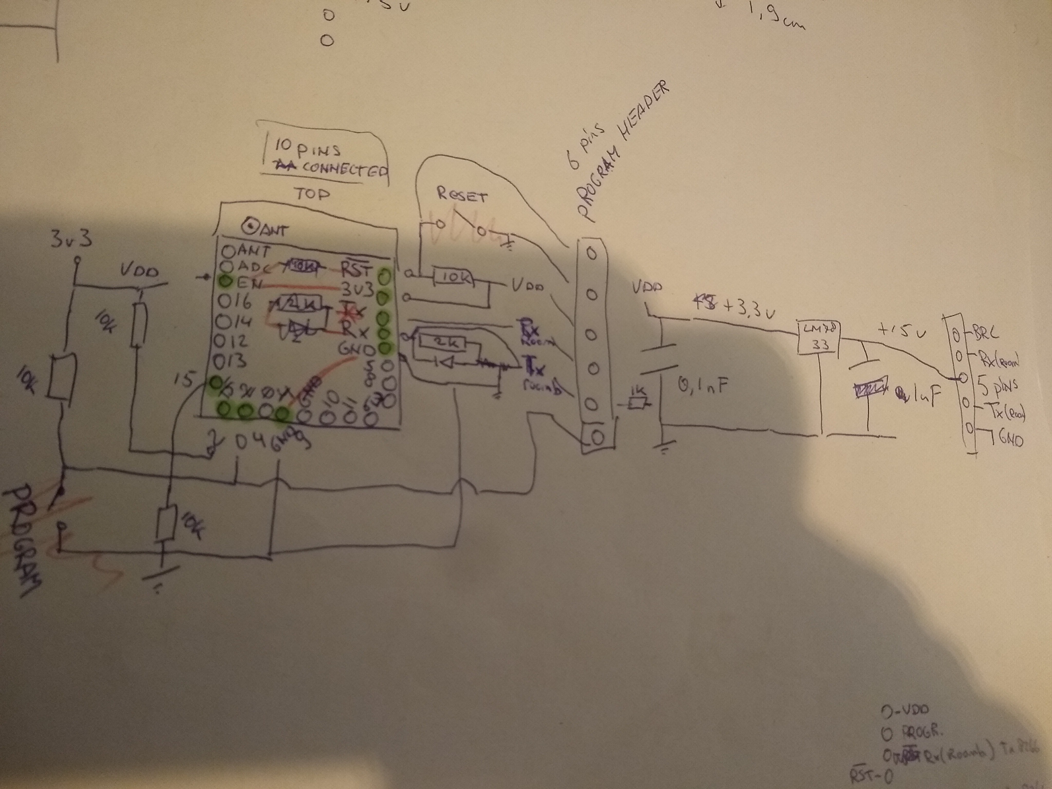
- The Rx pin on the (3.3V) ESP8266 will need the voltage divider level shifter to be connected to the (5V) Tx on the Roomba. Also a 3.3V Zener to GND, just to be sure;
- The Tx pin can be connected without any level shifting. The 3.3V is enough to be seen as a logic 1 by the Roomba;
- VDD: 3.3V (with 100nF);
- GND: on 2 pins;
The ESP8266 board I'm using needs some connections to get it in the proper boot- and operating mode:
- RSTB: Inverse reset. Pulled up with 10K to VDD;
- EN: Chip Enable. Connected straight to VDD;
- PRGB: UART programming select (inverse). Pulled up with 10K to VDD and connected to header so I can switch off-board;
- GPIO02: Pulled up with 10K to VDD to provide proper boot up mode. (will also be I2C_DATA pin for MPU6050);
- GPIO15: Pulled down with 10K to provide proper boot up mode. (will also receive interrupt from MPU6050 DMP, rising slope);
- GPIO14: Pulled up with 5k to VDD and will be connected to I2C_CLOCK pin on MPU6050;
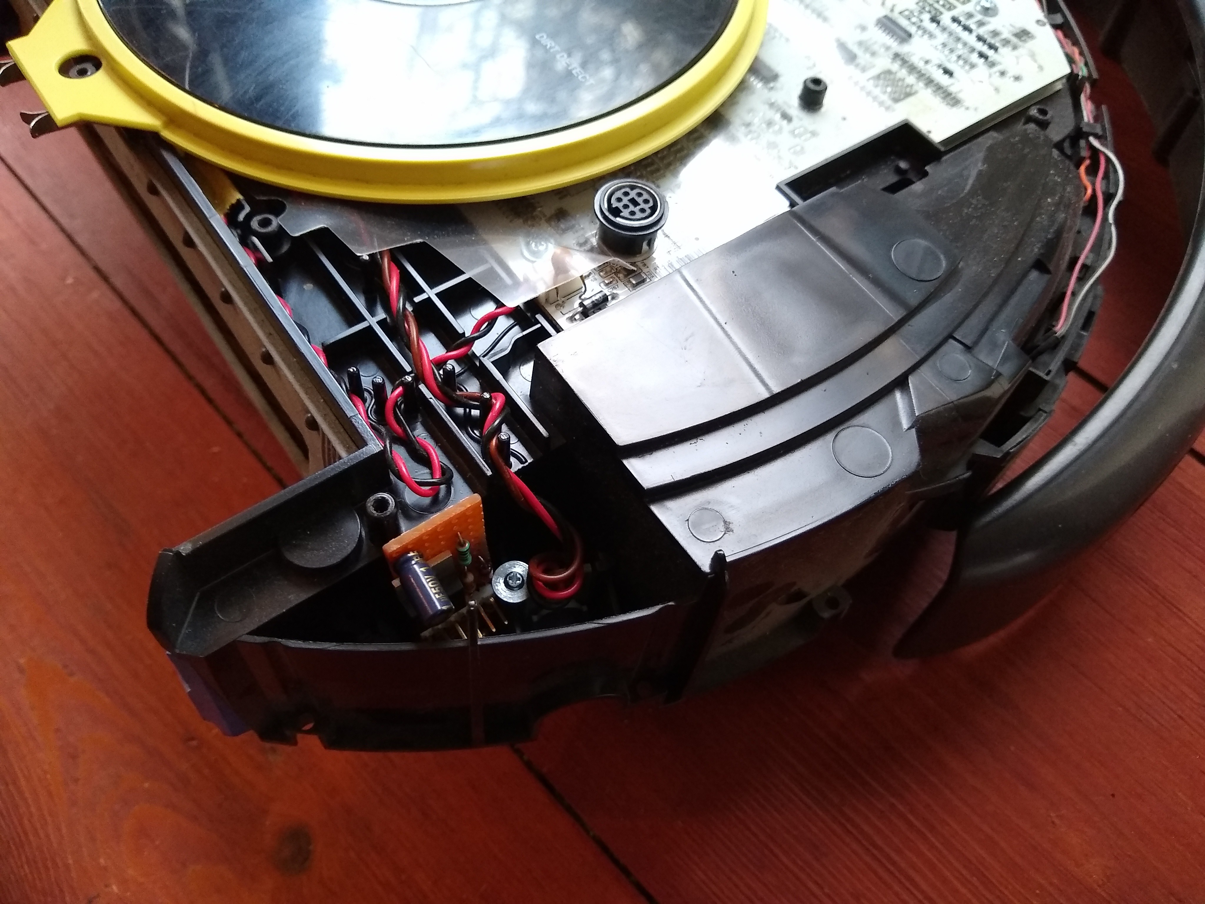
Time to open up the Roomba to find a empty space where my hardware can live:
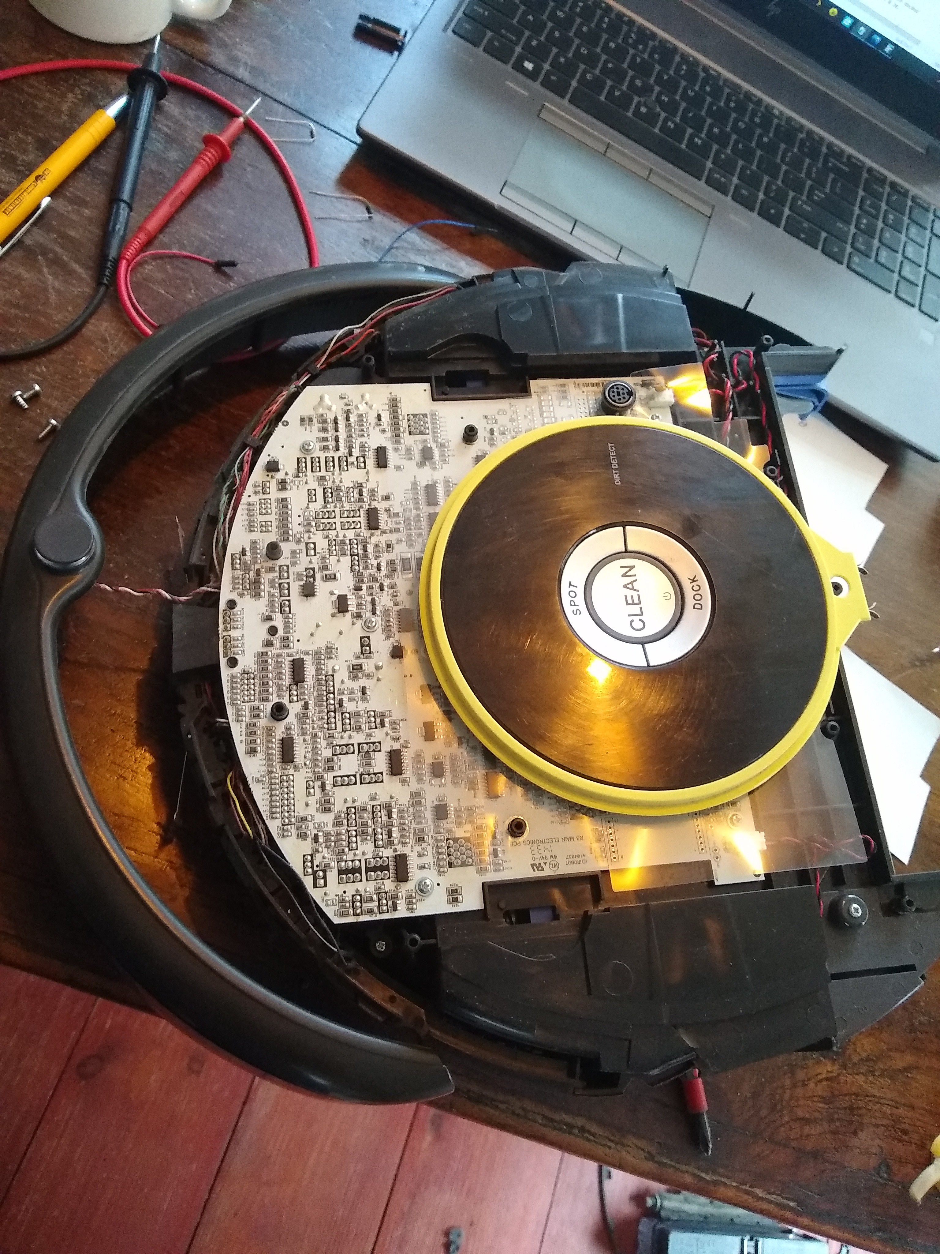
Behind the right wheel, there is space and it's quite close to the serial connector. Measuring gives me a board of 5.9cm x 1.9cm. Plenty!
Something like this:
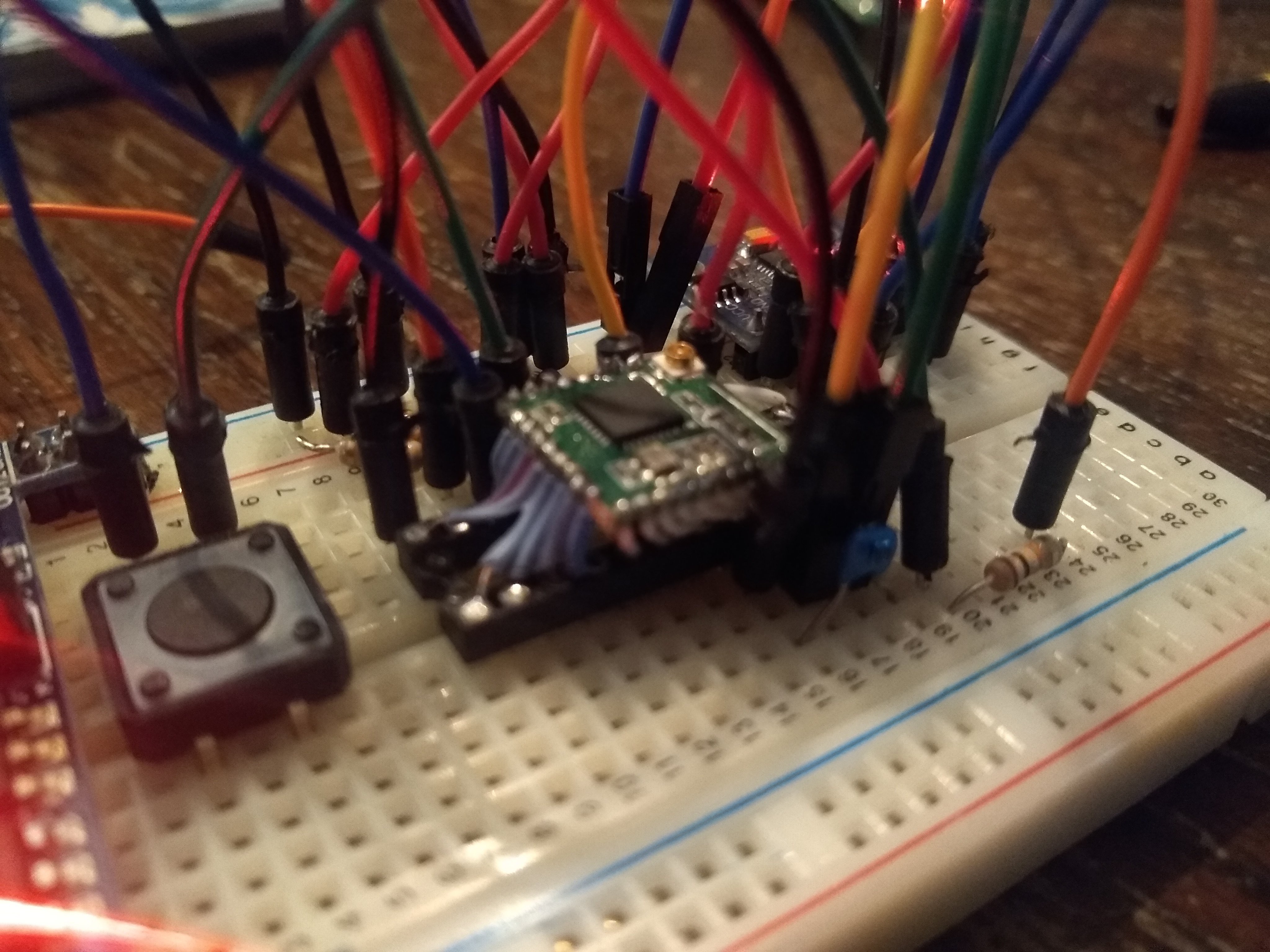
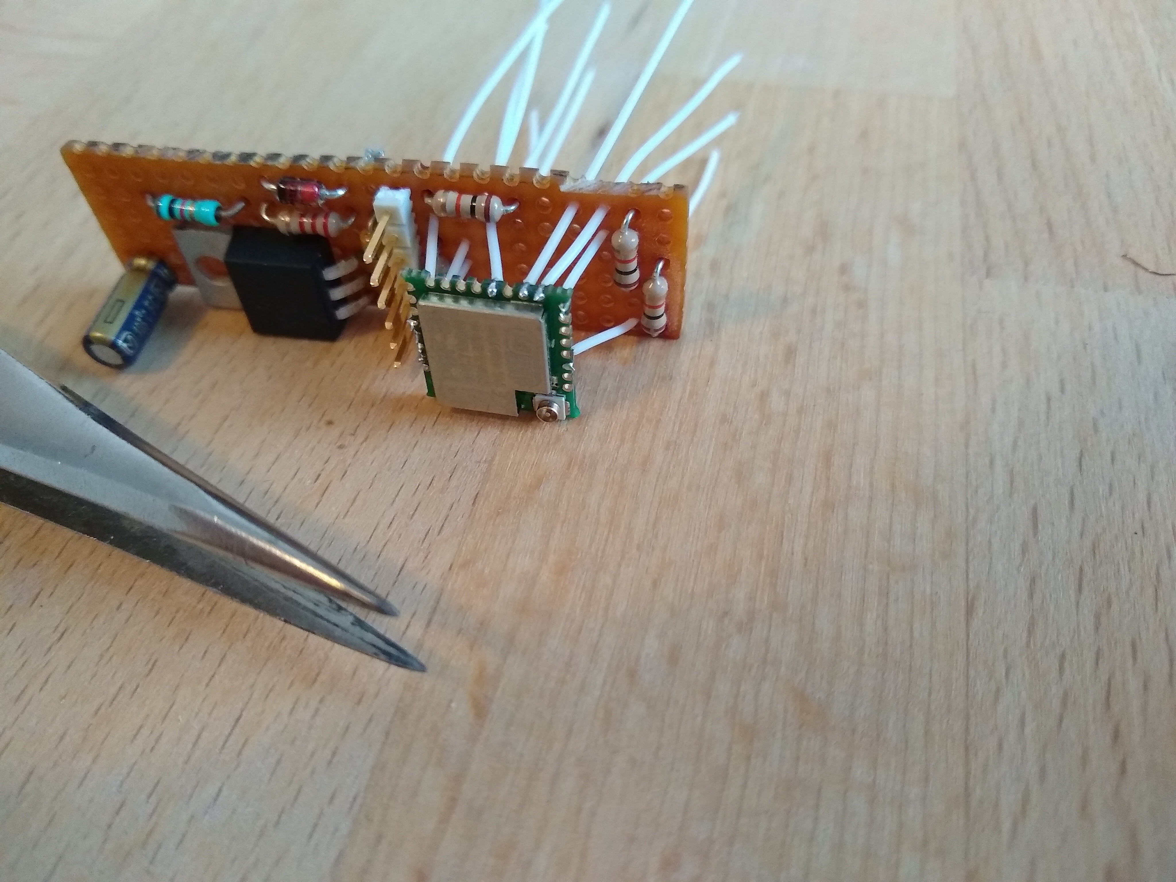
Testfit:
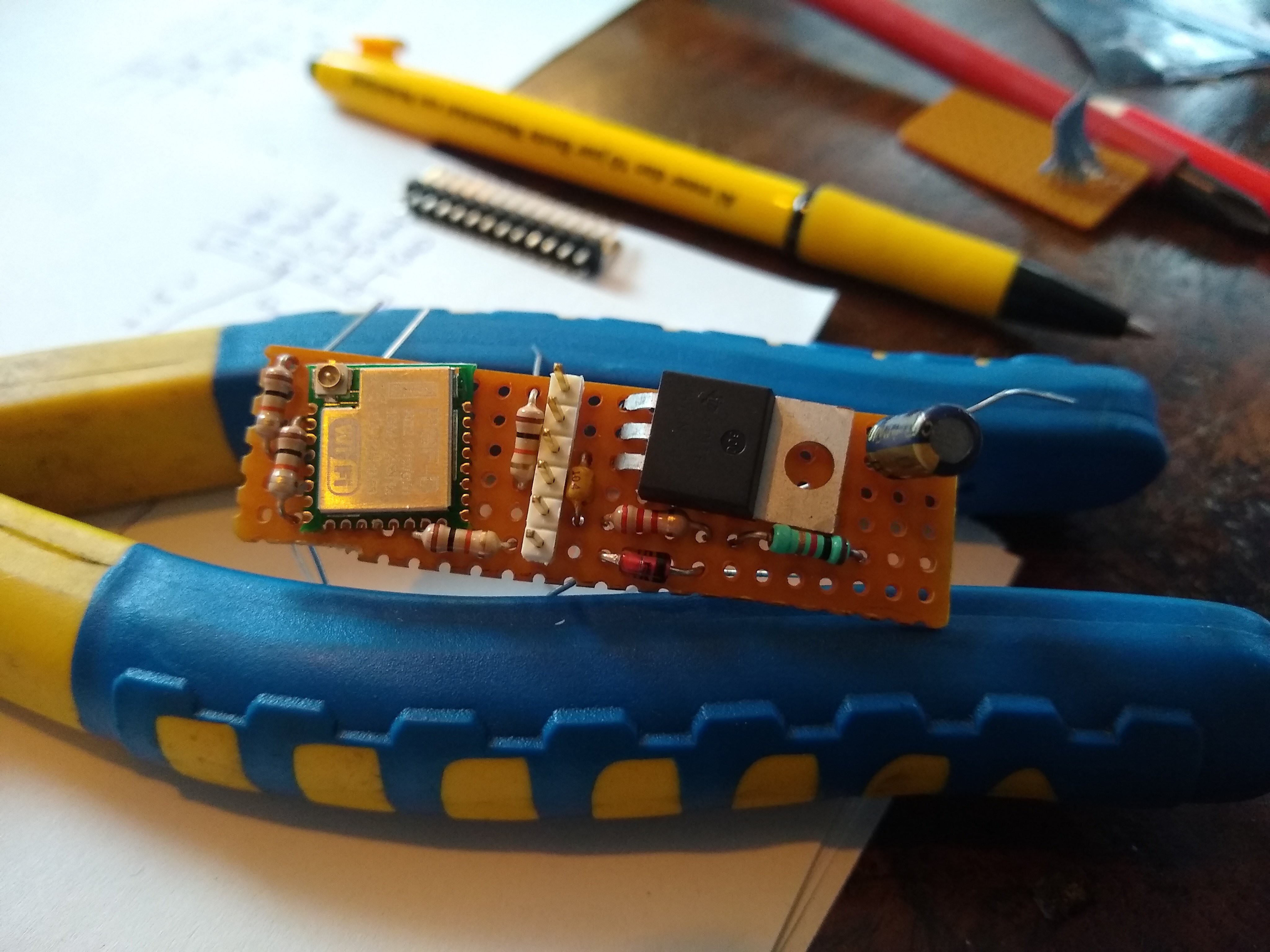
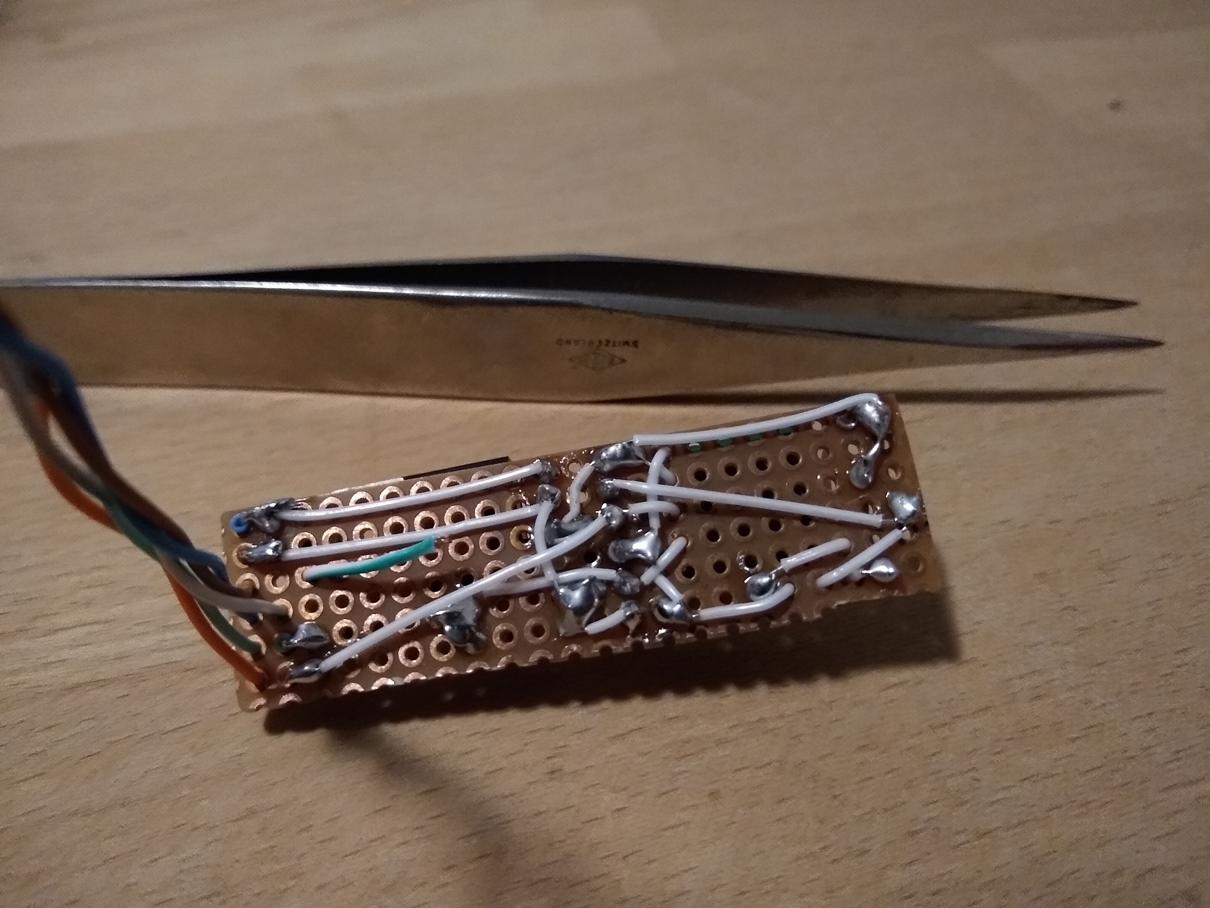
Finally some soldering:
And this is where I made the mistake to NOT correct myself when I mixed up the intended colours for the connection wires. I noticed it, but thought "this will be fine, I will remember".
Narrator: "But he didn't remember...."
Long story short: When connecting to the Roomba one time, I connected the ESP8266-Tx (orange) to the Roomba's raw battery voltage. So that's one ESP8266 down.. good thing they are cheap. I could also pretty neatly de-solder the unit and replace it with a new one.
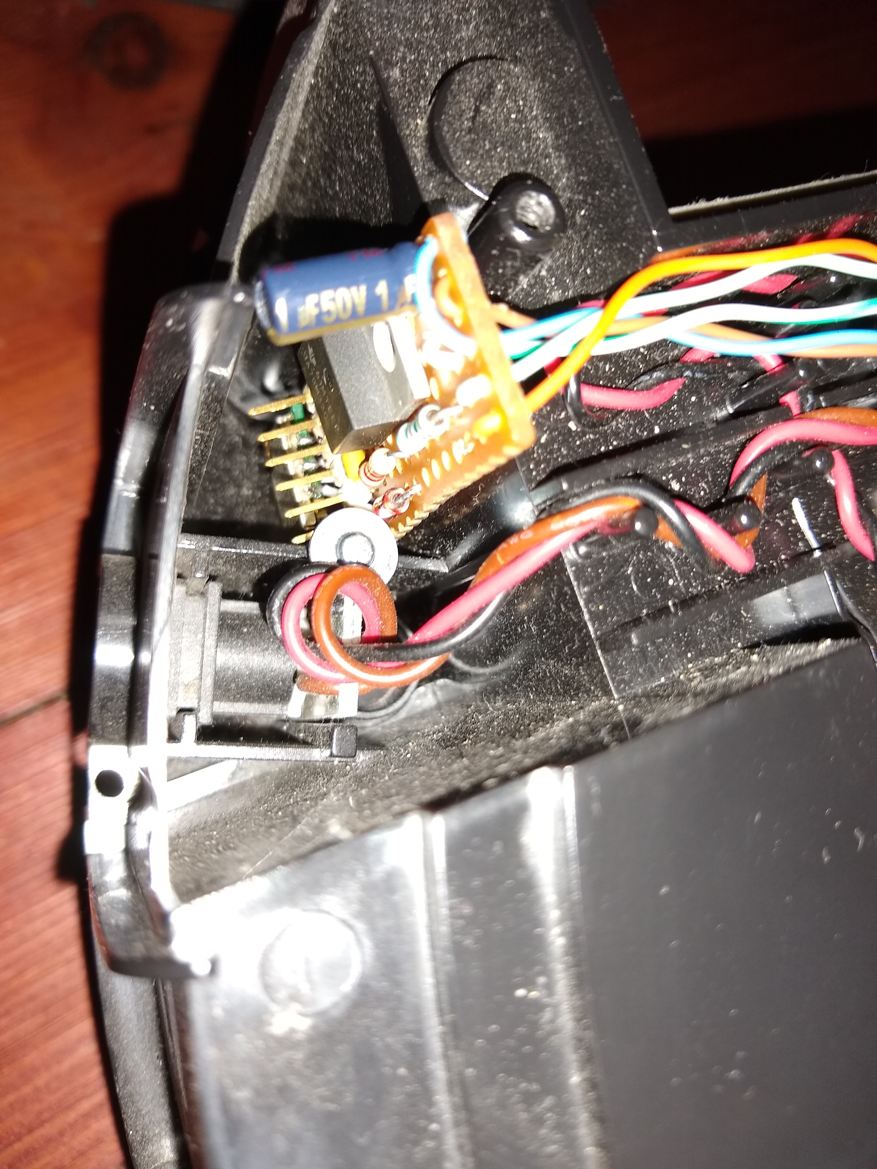
I connected the wires to the mini DIN7 connector by soldering the ends and just jamming them in. For the GND and VDD I bended two leads and soldered them to the end of the wires. So they can use two pins both.
From the docs: Pins 1 and 2 (Vpwr) are connected to the Roomba battery through a 200 mA PTC resettable fuse. The continuous draw from these two pins together should not exceed 200 mA. Do not draw more than 500 mA peak from these pins, or the fuse will reset.
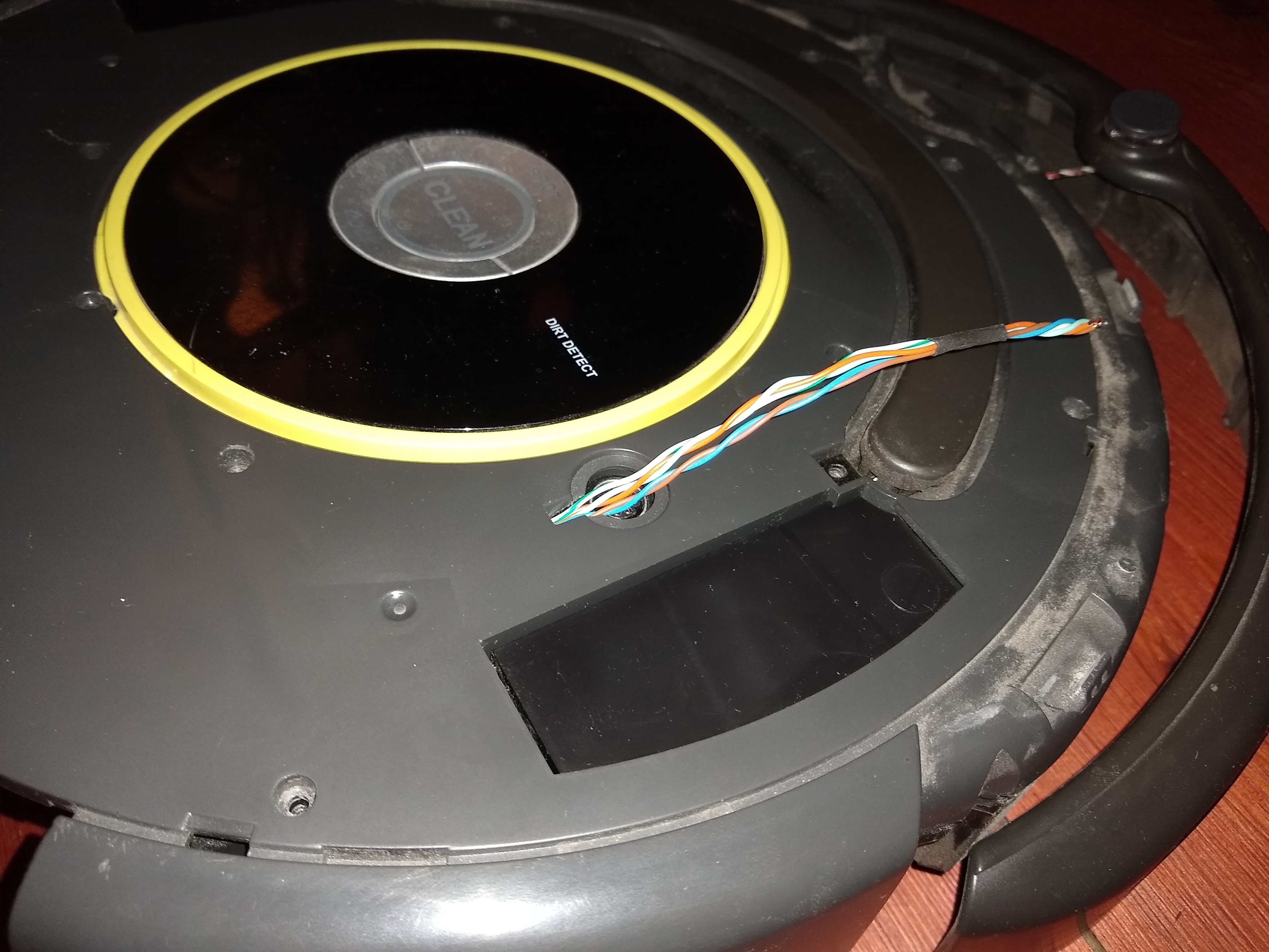
Also drilled one hole in the cover to let the wires come through. This will all be covered with a top plate and won't show.
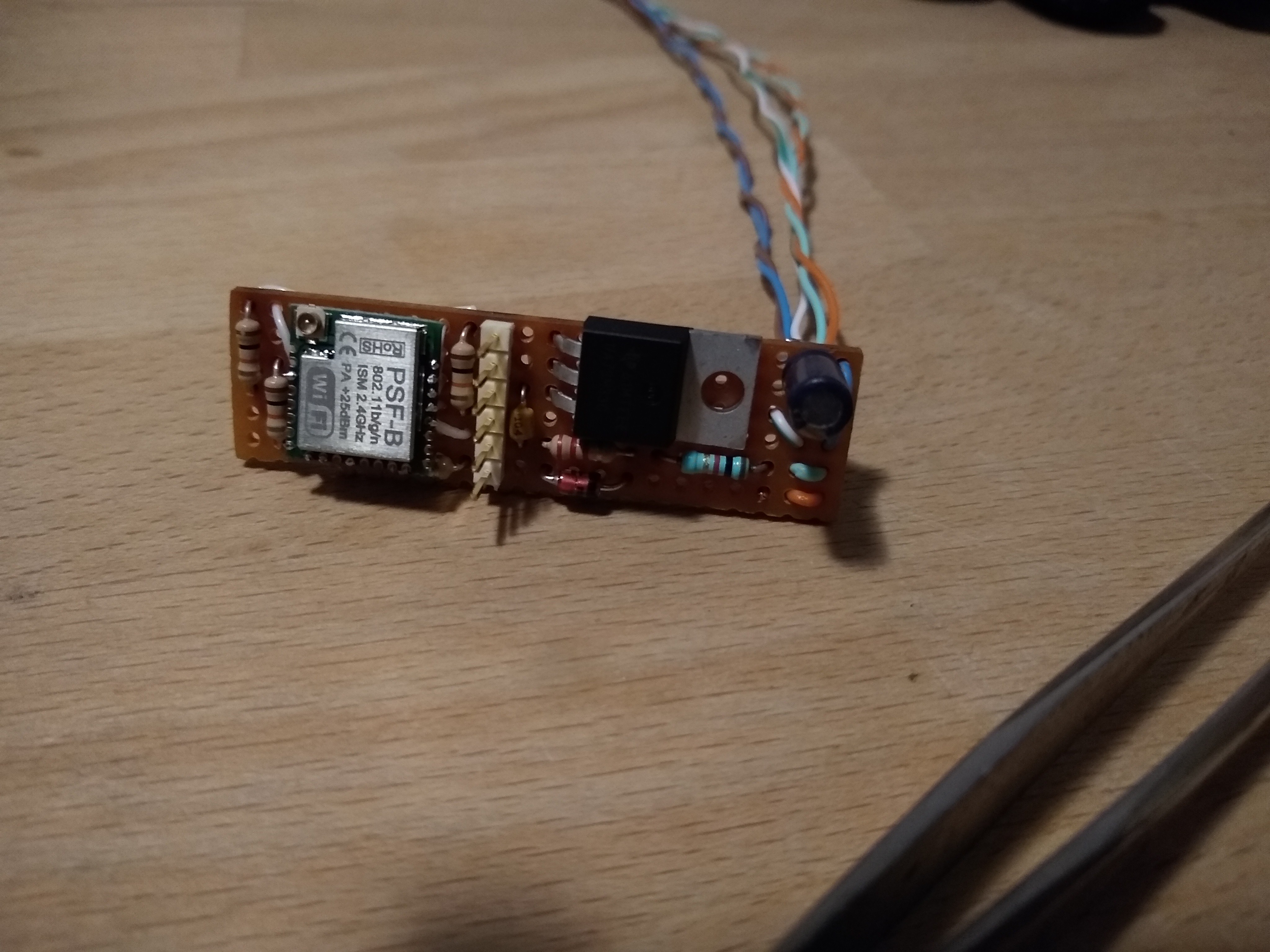
And the first version of the hardware is DONE!
As said, I will sort out the power situation. It works for now. Next up, SOFTWARE!
Discussions
Become a Hackaday.io Member
Create an account to leave a comment. Already have an account? Log In.