kevarek
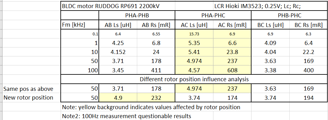
Phase LCR measurements summarized below.
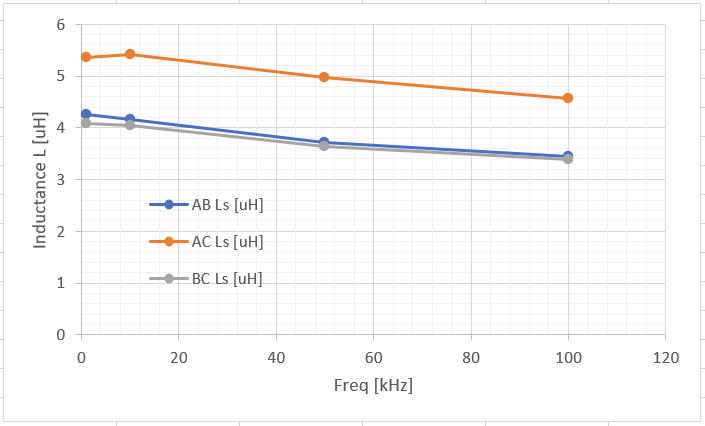
Inductance vs measurement frequency chart:
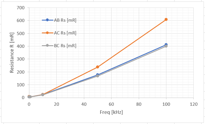
Resistance vs measurement frequency chart:
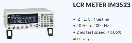
Taken with LCR meter Hioki IM3523:
DUT:
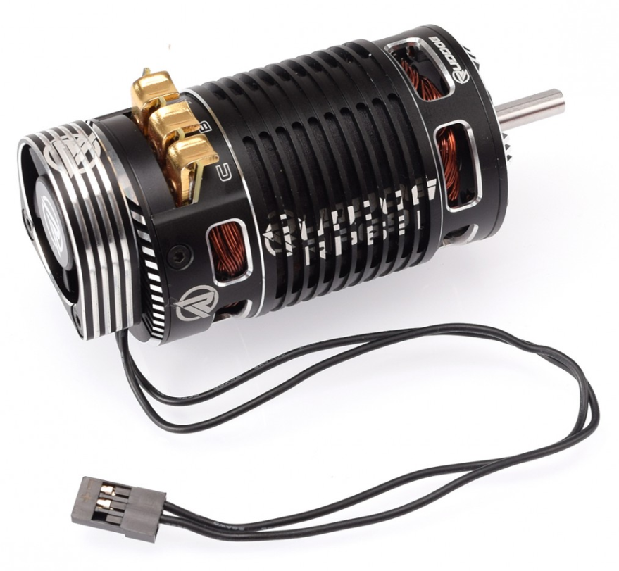
Since datasheet for this BLDC motor is not available, I will try to characterize its properties and share it here.
Already have an account? Log in.
To make the experience fit your profile, pick a username and tell us what interests you.
Phase LCR measurements summarized below.
Inductance vs measurement frequency chart:
Resistance vs measurement frequency chart:
Taken with LCR meter Hioki IM3523:
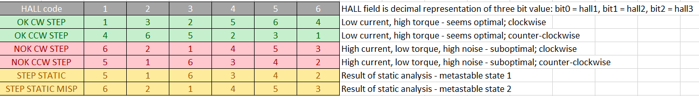
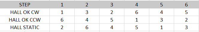
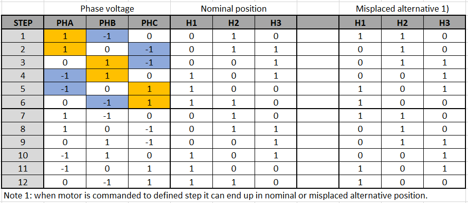
So I have learned that static analysis of step vs hall code will not result with usable table for commutation. Here is the table that is actually useful:
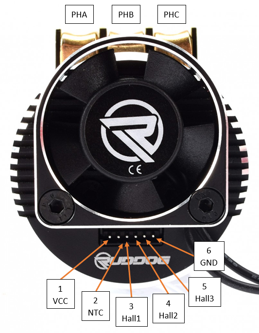
Pin 1: Supply voltage (both 3V3 and 5V tolerant).
Pin 2: NTC thermistor output (with respect to GND). 10kOhm @ 25 °C; Beta unknown for now.
Pin 3: Hall 1 output. Open drain. Seems to be related to Phase A.
Pin 4: Hall 2 output. Open drain. Seems to be related to Phase B.
Pin 5: Hall 3 output. Open drain. Seems to be related to Phase C.
Pin 6: Common ground.
Table with hall sensor output voltage relative to phase voltage (aka six step configuration - current step). Zero phase voltage indicates that phase is not driven by transistor half-bridge.
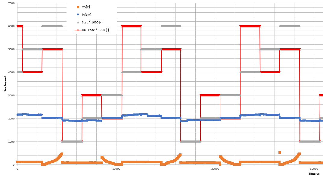
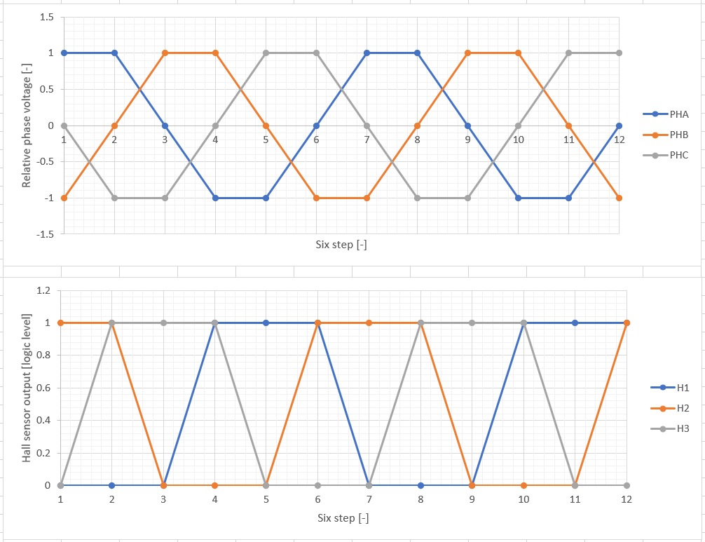
Visual representation of table above.